
3Com Switch 7750 Configuration Guide


634 CHAPTER 59: DHCP SNOOPING CONFIGURATION
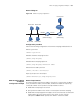
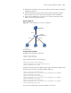
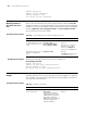
Network diagram
Figure 164 Network diagram for DHCP-snooping Option 82 support configuration
Configuration procedure
# Enable DHCP snooping on the switch.
<Switch> system-view
[Switch] dhcp-snooping
# Specify Ethernet 2/0/5 as the trusted port.
[Switch] interface Ethernet2/0/5
[Switch-Ethernet2/0/5] dhcp-snooping trust
[Switch-Ethernet2/0/5] quit
# Enable DHCP-snooping Option 82 support.
[Switch] dhcp-snooping information enable
# Set the remote ID sub-option in Option 82 to the system name of the DHCP
snooping device.
[Switch] dhcp-snooping information remote-id sysname
# Set the circuit ID sub-option in DHCP packets from VLAN 1 to abcd on Ethernet
2/0/3.
[Switch] interface Ethernet2/0/3
[Switch-Ethernet2/0/3] dhcp-snooping information vlan 1 circuit-id s
tring abcd
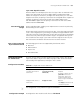
IP Filtering
Configuration Example
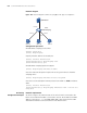
Network requirements
As shown in Figure 165, Ethernet 2/0/1 of the Switch 7750 is connected to the
DHCP server and Ethernet 2/0/2 is connected to Host A. The IP address and MAC
address of Host A are 1.1.1.1 and 0001-0001-0001 respectively. Ethernet 2/0/3
and Ethernet 2/0/4 are connected to DHCP Client B and Client C.
Eth2/0/2
Client B
Switch
DHCP-Snooping
Client A
Eth2/0/1
Client C
Eth2 /0/3
Eth2/0/5
DHCP Server