
3Com Switch 7750 Configuration Guide


694 CHAPTER 62: MIRRORING CONFIGURATION
Module. As for the distributed system, you can configure only one reflector
port of a remote source mirroring group or one destination port of a local
mirroring group for the whole system. Only one mirroring destination I/O
Module can be configured for the centralized or distributed system, and can be
referenced by only one local mirroring group.
Configuration example
1 Network requirements:
■ Switch A is connected to the data detect device via GigabitEthernet 2/0/2.
■ GigabitEthernet 2/0/1, the relay port of Switch A, is connected to
GigabitEthernet 2/0/1, the relay port of Switch B.
■ GigabitEthernet 2/0/2, the relay port of Switch B, is connected to
GigabitEthernet 2/0/1, the relay port of Switch C.
■ GigabitEthernet 2/0/2, the port of Switch C, is connected to PC1.
The purpose is to monitor and analyze the packets sent and received by PC1 via
the data detect device.
To meet the requirement above by using the remote port mirroring function,
perform the following configuration:
■ Define VLAN10 as remote-probe VLAN.
■ Define Switch A as the destination switch; configure GigabitEthernet 2/0/2, the
port that is connected to the data detect device, as the destination port for
remote mirroring. Set GigabitEthernet 2/0/2 to an Access port, where LACP
must be disabled and STP is recommended to be disabled.
■ Define Switch B as the intermediate switch.
■ Define Switch C as the source switch, GigabitEthernet 2/0/2 as the source port
for remote mirroring, and GigabitEthernet 2/0/3 as the reflector port. Set
GigabitEthernet 2/0/3 to an Access port, where LACP must be disabled and STP
is recommended to be disabled.
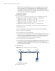
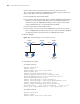
2 Network diagram
Figure 180 Network diagram for remote port mirroring
■ Configuration procedure
3 # Configure Switch C.
Switch C
GE2/0/1
PC1
Switch B Switch A
GE2/0/2 GE2/0/1
GE2/0/1
GE2/0/2GE2/0/2
Data detect
device
GE2/0/3