
3Com Switch 7750 Configuration Guide


700 CHAPTER 62: MIRRORING CONFIGURATION
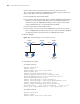
Use the remote traffic mirroring function to mirror the packets from the
10.1.1.1/24 network segment to GigabitEthernet 2/0/2, the port of Switch A, so
that the data detect device can monitor the traffic:
■ Define VLAN10 as remote-probe VLAN.
■ Define Switch A as the destination switch; configure GigabitEthernet 2/0/2, the
port that is connected to the data detect device, as the destination port for
remote mirroring. Set GigabitEthernet2/0/2 to an Access port, where LACP
must be disabled and STP is recommended to be disabled.
■ Define Switch B as the intermediate switch.
■ Define Switch C as the source switch, GigabitEthernet 2/0/3 as the reflector
port. Set GigabitEthernet 2/0/3 to an Access port, with STP and LACP disabled.
Configure the traffic mirroring function on GigabitEthernet 2/0/2.
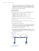
2 Network diagram
Figure 181 Network diagram for remote traffic mirroring
3 Configuration procedure
# Configure Switch A.
<SW7750> system-view
[SW7750] vlan 10
[SW7750-vlan10] remote-probe vlan enable
[SW7750-vlan10] quit
[SW7750] interface GigabitEthernet 2/0/1
[SW7750-GigabitEthernet2/0/1] port link-type trunk
[SW7750-GigabitEthernet2/0/1] port trunk permit vlan 10
[SW7750-GigabitEthernet2/0/1] quit
[SW7750] mirroring-group 1 remote-destination
[SW7750] mirroring-group 1 monitor-port GigabitEthernet 2/0/2
[SW7750] mirroring-group 1 remote-probe vlan 10
[SW7750] display mirroring-group remote-destination
mirroring-group 1: type: remote-destination status: active
monitor port: GigabitEthernet2/0/2 remote-probe vlan: 10
# Configure Switch B
<SW7750> system-view
[SW7750] vlan 10
[SW7750-vlan10] remote-probe vlan enable
Switch C
GE2/0/1
Switch B Switch A
GE2/0/2 GE2/0/1
GE2/0/1
GE2/0/2
GE2/0/2
Data detect
device
10.1.1.1/24
GE2/0/3