
3Com Switch 7750 Configuration Guide


714 CHAPTER 63: CLUSTER
Cluster Configuration
Example
Cluster Configuration
Example
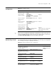
Network requirements
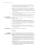
Three switches form a cluster, in which:
■ The management device is a Switch 7750.
■ The rest are member devices.
The Switch 7750 manages the rest two member devices as the management
device. The detailed information about the cluster is as follows.
■ The two member devices are connected to Ethernet1/0/2 and Ethernet1/0/3
ports of the management device.
■ The management device is connected to the external network through its
Ethernet1/0/1 port.
■ Ethernet1/0/1 port of the management device belongs to VLAN1, whose
interface IP address is 163.172.55.1.
■ All the devices in the cluster use the same FTP server and TFTP server.
■ The FTP server and TFTP server share one IP address: 163.172.55.2.
■ The SNMP site and log host share one IP address: 69.172.55.4.
Network diagram
Figure 184 Network diagram for Switch Clustering cluster configuration
Clear the NDP statistics on a
port
reset ndp statistics [ interface
port-list ]
-
Table 578 Display and maintain cluster configurations
Operation Command Description
䲚㕸
Internet
Eth 1/0/1
Eth 1 /0/3 Eth 1/0/2
Eth1 /1 Eth1/1
69 .172 .55 .4
SNMP/logging host(NMS)
FTP/TFTP Server
63.172.55.1
163.172 .55.1
VLAN 2 interface
Management device
Member DeviceMember Device
MAC:000 f .e201 .0011 M AC:000 f. e201 . 0012