
3Com Switch 7750 Configuration Guide


SNMP Configuration Example 745
SNMP Configuration
Example
SNMP Configuration
Example
Network requirements
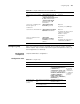
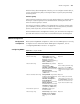
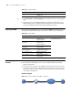
■ An NMS and Switch A are connected through the Ethernet. The IP address of
the NMS is 10.10.10.1 and that of the VLAN interface on Switch A is
10.10.10.2.
■ Perform the following configuration on Switch A: setting the community name
and access authority, administrator ID, contact and switch location, and
enabling the switch to sent trap packet.
Network diagram
Figure 190 Network diagram for SNMP
Network procedure
# Set the community name, group name and user.
Table 598 Display SNMP
Operation Command Description
Display system information of the current
SNMP device
display snmp-agent
sys-info [ contact |
location | version ]*
The display
command can
be executed in
any view
Display SNMP packet statistics information display snmp-agent
statistics
Display the switch fabric ID of the current
device
display
snmp-agent { local-switch
fabricid | remote-switch
fabricid }
Display group information about the device display snmp-agent group
[ group-name ]
Display SNMP user information display snmp-agent
usm-user [ switch fabricid
switch fabricid | username
user-name | group
group-name ]
Display the currently configured community
name
display snmp-agent
community [ read | write ]
Display the currently configured MIB view display snmp-agent
mib-view [ exclude |
include | viewname
view-name ]
Ethernet
10.10.10.1
NMS
10.10.10.2
Switch A