
3Com Switch 7750 Configuration Guide


754 CHAPTER 70: NTP CONFIGURATION
with the increasing of stratum number. The clocks with the stratum of 16 are in
unsynchronized state and cannot serve as reference clocks.
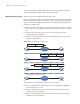
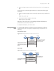
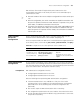
Working Principle of NTP Figure 192 shows the implementation principle of NTP.
Ethernet switch A (Device A) is connected to Ethernet switch B (Device B) through
Ethernet ports. Both having their own system clocks, they need to synchronize the
clocks of each other through NTP. To help you to understand the implementation
principle, we suppose that:
■ Before the system clocks of Device A and Device B are synchronized, the clock
of Device A is set to 10:00:00 am, and the clock of Device B is set to 11:00:00
am.
■ Device B serves as the NTP server, that is, the clock of Device A will be
synchronized to that of Device B.
■ It takes one second to transfer an NTP message from Device A to Device B or
from Device B to Device A.
Figure 192 Implementation principle of NTP
The procedure of synchronizing the system clock is as follows:
■ Device A sends an NTP message to Device B, with a timestamp 10:00:00 am
(T
1
) identifying when it is sent.
■ When the message arrives at Device B, Device B inserts its own timestamp
11:00:01 am (T
2
) into the packet.
■ When the NTP message leaves Device B, Device B inserts its own timestamp
11:00:02 am (T
3
) into the packet.
IP network
IP network
IP network
IP network
Device BDevice A
Device B
Device A
Device B
Device A
Device B
Device A
10:00:00 am 11:00:01 am
10:00:00 am
NTP message 10:00:00 am 11:00:01 am 11:00:02 am
NTP message
NTP message
NTP message received at 10:00:03 am
1.
3.
2.
4.