
3Com Switch 7750 Configuration Guide


Introduction to NTP 755
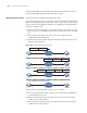
■ When receiving a response packet, the local time of Device A is 10:00:03 am
(T4).
At this time, Device A has enough information to calculate the following two
parameters:
■ Delay for an NTP message to make a round trip between Device A and Device
B:
Delay = (T
4
-T
1
)-(T
3
-T
2
).
■ Time offset of Device A relative to Device B:
Offset = ((T
2
-T
1
) + (T
3
-T
4
))/2.
Device A can then set its own clock according to the above information to
synchronize its clock to that of Device B.
For detailed information, refer to RFC 1305.
NTP Implementation
Mode
To accommodate networks of different structures and switches in different
network positions, NTP can operate in multiple modes, as described in the
following.
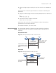
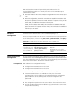
Client/Server mode
Figure 193 NTP implementation mode: client/Sever mode
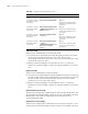
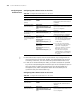
Peer mode
Figure 194 NTP implementation mode: peer mode
Server
Clock synchronization
request packet
Response packet
Network
Client
Works in server mode
automatically and send
a response packet
Filters and selects a clocks
and synchronize the local
clock to that of the preferred
server
Passive peer
Clock synchronization
request packet
Synchronize
Network
Active peer
Works in passive peer
mode automatically
In peer mode, both sides
can be synchronized to
each other
Response packet