
3Com Switch 7750 Configuration Guide


88 CHAPTER 10: VLAN OVERVIEW
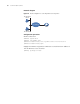
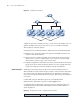
Figure 25 A VLAN implementation
A VLAN can span across multiple switches, or even routers. This enables hosts in a
VLAN to be dispersed in a looser way. That is, hosts in a VLAN can belong to
different physical network segment.
Compared with the traditional Ethernet, VLAN enjoys the following advantages.
■ Broadcasts are confined to VLANs. This decreases bandwidth utilization and
improves network performance.
■ Network security is improved. VLANs cannot communicate with each other
directly. That is, a host in a VLAN cannot access resources in another VLAN
directly, unless routers or Layer 3 switches are used.
■ Network configuration workload for the host is reduced. VLAN can be used to
group specific hosts. When the physical position of a host changes within the
range of the VLAN, you need not change its network configuration.
VLAN Principles VLAN tags in the packets are necessary for the switch to identify packets of
different VLANs. The switch works at Layer 2 (Layer 3 switches are not discussed in
this chapter) and it can identify the data link layer encapsulation of the packet
only, so you can add the VLAN tag field into only the data link layer encapsulation
if necessary.
In 1999, IEEE issues the IEEE 802.1Q protocol to standardize VLAN
implementation, defining the structure of VLAN-tagged packets.
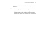
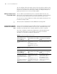
In traditional Ethernet data frames, the type field of the upper layer protocol is
encapsulated after the destination MAC address and source MAC address, as
shown in Figure 26
Figure 26 Encapsulation format of traditional Ethernet frames
Switch
Router
Switch
VLAN A VLANB VLAN A VLANB
VLAN A VLAN B
Type DataDA&SA