
3Com Switch 7750 Configuration Guide


918 CHAPTER 82: RRPP CONFIGURATION
Ethernet2/0/1 secondary-port GigabitEthernet2/0/2 level 0
[SW7750-rrpp-domain-1] ring 1 enable
[SW7750-rrpp-domain-1] quit
[SW7750] rrpp enable
■ Configure Switch D
<SW7750> system-view
[SW7750] rrpp domain 1
[SW7750-rrpp-domain-1] control-vlan 4092
[SW7750-rrpp-domain-1] ring 1 node-mode transit primary-port Gigabit
Ethernet2/0/1 secondary-port GigabitEthernet2/0/2 level 0
[SW7750-rrpp-domain-1] ring 1 enable
[SW7750-rrpp-domain-1] quit
[SW7750] rrpp enable
After the configuration, you can use the display command to view the RRPP
configuration and packet statistics.
Intersectant Ring
Network Configuration
Example
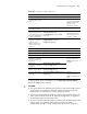
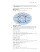
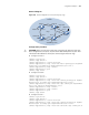
Network requirements
■ Switch A, Switch B, Switch C, Switch D and Switch E constitute RRPP domain 1
■ VLAN 4092 is the control VLAN of RRPP domain 1
■ Switch A, Switch B, Switch C and Switch D constitute primary ring 1.
■ Switch B, Switch C and Switch E form the subring 2.
■ Switch A serves as the master node of the primary ring, GigabitEthernet2/0/1
as the primary port, and GigabitEthernet2/0/2 as the secondary port.
■ Switch E serves as the master node of the subring, its GigabitEthernet2/0/1 is
the primary port, and its GigabitEthernet2/0/2 is the secondary port.
■ Switch B serves as a transit node of the primary ring and the edge node of the
subring, its GigabitEthernet2/0/2 is the common port, and its
GigabitEthernet2/0/3 is the edge port.
■ Switch C serves as a transit node of the primary ring and an assistant edge
node of the subring, its GigabitEthernet2/0/1 is a common port, and its
GigabitEthernet2/0/3 is an edge port.
■ Switch D serves as a transit node of the primary ring, its GigabitEthernet2/0/1 is
the primary port, and its GigabitEthernet2/0/2 is the secondary port.
■ The default values are used for the timer on the primary ring and the subring.