
3Com Switch 7750 Configuration Guide


Configuration Example 919
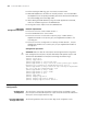
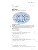
Network diagram
Figure 255 Network diagram for intersectant ring topology
Configuration procedure
c
CAUTION: Make sure that the switch ports connecting the Ethernet rings have
been configured as trunk ports. All ports allow data VLAN packets to pass. And
STP has been disenabled on all the ports connecting the Ethernet rings.
■ Configure Switch A
<SW7750> system-view
[SW7750] rrpp domain 1
[SW7750-rrpp-domain-1] control-vlan 4092
[SW7750-rrpp-domain-1] ring 1 node-mode master primary-port GigabitE
thernet2/0/1 secondary-port GigabitEthernet2/0/2 level 0
[SW7750-rrpp-domain-1] ring 1 enable
[SW7750-rrpp-domain-1] quit
[SW7750] rrpp enable
■ Configure Switch B
<SW7750> system-view
[SW7750] rrpp domain 1
[SW7750-rrpp-domain-1] control-vlan 4092
[SW7750-rrpp-domain-1] ring 1 node-mode transit primary-port Gigabit
Ethernet2/0/1 secondary-port GigabitEthernet2/0/2 level 0
[SW7750-rrpp-domain-1] ring 2 node-mode edge common-port GigabitEthe
rnet 2/0/2 edge-port GigabitEthernet 2/0/3
[SW7750-rrpp-domain-1] ring 1 enable
[SW7750-rrpp-domain-1] ring 2 enable
[SW7750-rrpp-domain-1] quit
[SW7750] rrpp enable
■ Configure Switch C
<SW7750> system-view
[SW7750] rrpp domain 1
[SW7750-rrpp-domain-1] control-vlan 4092
[SW7750-rrpp-domain-1] ring 1 node-mode transit primary-port Gigabit
Ethernet2/0/1 secondary-port GigabitEthernet2/0/2 level 0
[SW7750-rrpp-domain-1] ring 2 node-mode assistant-edge common-port G
GE2/0/1
GE2/0/2
GE2/0/1
GE2/0/2
GE2/0/1
GE2/0/2
GE2/0/1
GE2/0/2
GE2/0/3
GE2/0/3
Switch A Switch B
Switch C
Switch D
Switch E
Edge node
Master node
Transit node
Assistant edge node
Domain 1
Ring 1
Ring 2
GE2/0/1
GE2/0/2
Master node