
3Com Switch 7750 Configuration Guide

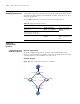

Smart Link Configuration Example 929
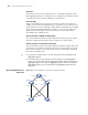
Configuration procedure
1 Configure a Smart Link group on Switch A and configure member ports for it.
Enable the function of sending flush messages in Control VLAN 1.
# Enter system view.
<switchA> system-view
# Enter Ethernet port view. Disable STP on Ethernet2/0/1 and Ethernet2/0/2.
[SwitchA] interface Ethernet 2/0/1
[SwitchA-Ethernet2/0/1] stp disable
[SwitchA-Ethernet2/0/1] quit
[SwitchA] interface Ethernet 2/0/2
[SwitchA-Ethernet2/0/2] stp disable
# Return to system view.
[SwitchA-Ethernet2/0/2] quit
# Create Smart Link group 1 and enter the corresponding Smart Link group view.
[SwitchA] smart-link group 1
# Configure Ethernet2/0/1 as the master port and Ethernet2/0/2 as the slave port
for Smart Link group 1.
[SwitchA-smlk-group1] port Ethernet 2/0/1 master
[SwitchA-smlk-group1] port Ethernet 2/0/2 slave
# Configure to send flush messages within VLAN 1.
[SwitchA-smlk-group1] flush enable control-vlan 1
2 Enable the function of processing flush messages received from VLAN 1 on Switch
C.
# Enter system view.
<SwitchC> system-view
# Enable the function of processing flush messages received from VLAN 1 on
Ethernet 2/0/2.
<SwitchC> smart-link flush enable control-vlan 1 port Ethernet 2/0/2
3 Enable the function of processing flush messages received from VLAN 1 on Switch
D.
# Enter system view.
<SwitchD> system-view
# Enable the function of processing flush messages received from VLAN 1 on
Ethernet 2/0/2.
[SwitchD] smart-link flush enable control-vlan 1 port Ethernet 2/0/2