
3Com Switch 7750 Configuration Guide


Monitor Link Configuration Example 935
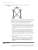
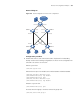
Network diagram
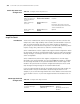
Figure 261 Network diagram for Monitor Link configuration
Configuration procedure
1 Enable Smart Link on Switch A and Switch B to implement link redundancy
backup. Perform the following configuration on Switch A. The configuration on
Switch B is the same as on Switch A.
# Enter system view.
<switchA> system-view
# Enter Ethernet port view. Disable STP on Ethernet2/0/1 and Ethernet2/0/2.
[SwitchA] interface Ethernet 2/0/1
[SwitchA-Ethernet2/0/1] stp disable
[SwitchA-Ethernet2/0/1] quit
[SwitchA] interface Ethernet 2/0/2
[SwitchA-Ethernet2/0/2] stp disable
# Return to system view.
[SwitchA-Ethernet2/0/2] quit
# Create Smart Link group 1 and enter Smart Link group view.
[SwitchA] smart-link group 1
BLOCK
Switch A Switch B
Eth1/0/1
Eth1/0/2
Switch C Switch D
Switch E
Eth1/0/1
Eth1/0/2
Eth1/0/3
Server
Eth1 /0/2
Eth1 /0/2
Eth1 /0/1
Eth1/0/1
Eth1/0/3
Eth1 /0/11Eth1/0/10
PC 1 PC 4PC 3PC 2
Internet