
3Com Switch 7750 Installation Guide


48 CHAPTER 2: INSTALLING THE SWITCH 7750
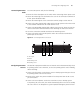
Follow the parameters defined in Table 48 for binding cables with ties.
Post-installation
Checklist
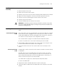
After you install your switch, use the checklist in Table 49 to verify that your switch
operates correctly.
WARNING: Confirm that you have turned off the power before checking your
installation. Improper connections can injure people or damage components of
the switch.
Tabl e 48 Cable Binding Parameters
Cable Bundle Diameter Space Between Bundles
10 mm (0.5in) 80-150 mm (3.5 – 6 in)
10-30 mm (.5 – 1.2 in) 150-200 mm (6 – 8 in)
30 mm (1.2 in) 200-300 mm (8 – 12 in)
Tabl e 49 Installation Checklist
Item Normal Abnormal (Remarks)
Antistatic wrist strap
Console cable
Ground wire
Power cord
Fabric
I/O module
Fan frame