
3Com Switch 8800 Family Configuration Guide


124 CHAPTER 17: MSTP REGION-CONFIGURATION
A port can play different roles in different spanning tree instances.
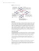
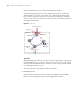
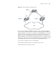
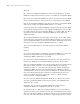
The following figure illustrates the earlier-mentioned concepts for your better
understanding. In this figure, the switch A, B, C, and D make up a MST region.
Port 1 and 2 on switch A connects to the common root bridge; port 5 and 6 on
switch C forms a loop; port 3 and 4 on switch D connects to other MST regions in
the downstream direction.
Figure 24 Port roles
TC packet
Topology change (TC) means the structure of the MSTP spanning tree changes due
to some bridge change or some port change on the network. In versatile routing
platform (Comware) implementation, when a port state changes from discarding
to forwarding, it means TC occurs.
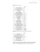
The following section describes two kinds of STP packets:
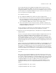
1 MSTP BPDU packet
MSTP modules communicate with each other among bridges by MSTP BPDU
packets. The following figure shows the MSTP BPDU packet format:
C
A
B
D
Port 1
Port 2
Master port
Alternate port
Port 3 Port 4
Port 5
Port 6
Backup port
Edge port
Designated
port
Connect to the root
MST area