
3Com Switch 8800 Family Configuration Guide


126 CHAPTER 17: MSTP REGION-CONFIGURATION
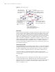
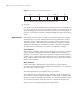
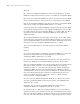
Figure 27 Meaning of 1-byte Flags in BPDU packets
The second and third bits together indicate MSTP port role.
2 TC packet
A TC packet is also an MSTP BPDU packet, but the lowest bit of its flags field is set
to 1, which endows the TC packet with special meaning. So the TC packet has its
special meaning. After receiving or detecting TC packets, a port will broadcast TC
packets to tell the whole network the changed topology information at the fastest
speed.
MSTP Principles MSTP divides the entire Layer 2 network into several MST regions and calculates
and generates CST for them. Multiple spanning trees are generated in a region
and each of them is called an MSTI. The instance 0 is called IST, and others are
called MSTI. Similar to RSTP, MSTP also use configuration messages to calculate
and generate spanning trees, the difference is that it is the MSTP configuration
information on the switches that is carried in the configuration messages.
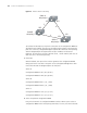
CIST calculation
The CIST root is the highest-priority switch elected from the switches on the entire
network through comparing their configuration BPDUs. MSTP calculates and
generates IST in each MST region; at the same time it regards each MST region as
a single "switch" and then calculates and generates the CST between the regions.
The CST and ISTs together make up the CIST which connects all the switches in the
whole switching network.
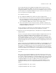
MSTI calculation
Inside an MST region, MSTP generates different MSTIs for different VLANs
according to the association between VLAN and the spanning tree. The calculation
process of MSTI is like that of RSTP.
The following introduces the calculation process of one MSTI.
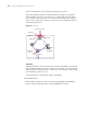
The fundamental of STP is that the switches exchange a special kind of protocol
packet (which is called configuration Bridge Protocol Data Units, or BPDU, in IEEE
802.1D) to decide the topology of the network. The configuration BPDU contains
the information enough to ensure the switches to compute the spanning tree.
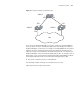
Figure 28 shows the Designated bridge and designated port.
7 6 5 4 3 2 1 0
TcProposalLearningForwardingAgreementTc Ac k
7 6 5 4 3 2 1 0
TcProposalLearningForwardingAgreementTc Ac k