
3Com Switch 8800 Family Configuration Guide


128 CHAPTER 17: MSTP REGION-CONFIGURATION
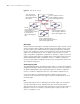
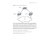
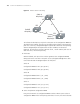
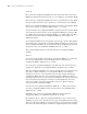
Figure 29 Ethernet switch networking
To facilitate the descriptions, only the first four parts of the configuration BPDU are
described in the example. They are root ID (expressed as Ethernet switch priority),
path cost to the root, designated bridge ID (expressed as Ethernet switch priority)
and the designated port ID (expressed as the port number). As illustrated
Figure 29, the priorities of Switch A, B and C are 0, 1 and 2 and the path costs of
their links are 5, 10 and 4 respectively.
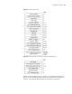
1 Initial state
When initialized, each port of the switches generates the configuration BPDU
taking itself as the root with a root path cost as 0, designated bridge IDs as their
own switch IDs and the designated ports as their ports.
Switch A:
Configuration BPDU of AP1: {0, 0, 0, AP1}
Configuration BPDU of AP2: {0, 0, 0, AP2}
Switch B:
Configuration BPDU of BP1: {1, 0, 1, BP1}
Configuration BPDU of BP2: {1, 0, 1, BP2}
Switch C:
Configuration BPDU of CP2: {2, 0, 2, CP2}
Configuration BPDU of CP1: {2, 0, 2, CP1}
2 Select the optimum configuration BPDU
Every switch transmits its configuration BPDU to others. When a port receives a
configuration BPDU with a lower priority than that of its own, the switch discards
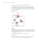
Switch A
with priority 0
Switch C
with priority 2
Switch B
with priority 1
CP2
BP2
CP1
BP1
AP2
AP1
4
10
5