
3Com Switch 8800 Family Configuration Guide


Introduction to MSTP 131
For example, the link from Switch B to Switch C is down or the port receives any
better configuration BPDU
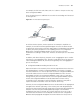
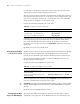
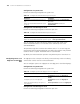
Thus, the spanning tree is stabilized. The tree with the root bridge A is illustrated
in the
Figure 30.
Figure 30 The final stabilized spanning tree
To facilitate the descriptions, the description of the example is simplified. For
example, the root ID and the Designated bridge ID in actual calculation should
comprise both switch priority and switch MAC address. Designated port ID should
comprise port priority and port ID. In the updating process of a configuration
BPDU, other configuration BPDUs besides the first four items will make
modifications according to certain rules. The basic calculation process is described
below:
In addition, with identical priority, the path cost of an aggregation port is smaller
than that of a non-aggregation port. Therefore, under identical root ID, path cost
value and designated switch ID, the switch will generally select the aggregation
port as the root port.
■ Configuration BPDU forwarding mechanism in STP:
Upon the initiation of the network, all the switches regard themselves as the roots.
The designated ports send the configuration BPDUs of local ports at a regular
interval of HelloTime. If it is the root port that receives the configuration BPDU, the
switch will enable a timer to time the configuration BPDU as well as increase
MessageAge carried in the configuration BPDU by certain rules. If a path goes
wrong, the root port on this path will not receive configuration BPDUs any more
and the old configuration BPDUs will be discarded due to timeout. Hence,
recalculation of the spanning tree will be initiated to generate a new path to
replace the failed one and thus restore the network connectivity.
However, the new configuration BPDU as now recalculated will not be propagated
throughout the network right away, so the old root ports and designated ports
that have not detected the topology change will still forward the data through the
old path. If the new root port and designated port begin to forward data
immediately after they are elected, an occasional loop may still occur. In STP, a
transitional state mechanism is thus adopted to ensure the new configuration
BPDU has been propagated throughout the network before the root port and
Switch A
priority level as 0
Switch C
priority level as 2
Switch B
priority level as 1
CP2
BP2
BP1
AP1
4
5