
3Com Switch 8800 Family Configuration Guide

Basic Portal Configuration 275
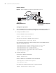
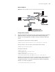
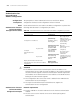
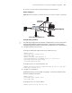
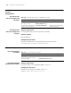
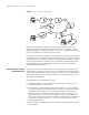
Network diagram
Figure 67 Network diagram for Layer 3 Portal authentication method
Configuration procedure
n
Only the configurations related to the Layer 3 Portal authentication method are
listed below. Refer to
“Portal Direct Authentication Method Configuration
Example” for the configurations on RADIUS schemes, ISP domains and Portal
servers.
# Configure the authentication network segment
[SW8800] portal auth-network 162.31.0.0 255.255.0.0 vlan 100
# Set the Portal to run in the Layer 3 Portal authentication method
[SW8800] portal method layer3
# Configure VLAN 100
[SW8800] vlan 100
[3Com-vlan100] port ethernet 2/1/6
[3Com-vlan100] quit
[SW8800] interface vlan-interface 100
[3Com-Vlan-interface100] ip address 162.21.1.1 255.255.0.0
# Enable Portal authentication function on VLAN-interface 100. The name of the
Portal server is newp. Refer to section
“Portal Direct Authentication Method
Configuration Example” “Portal Direct Authentication Method Configuration
Example” for related configurations.
[3Com-Vlan-interface100] portal newp
Switch
Portal
RADIUS
Vlan-interfac e 2
192.168.1. 160/ 16
192.168.1. 100/ 16
192.168.1. 200/ 16
VLAN 2
User PC2
Gateway address
:162.31. 1.1
IP addr ess:162.31.1. 2/16
162.31.1.1/16
Ethernet 0/0
Ethernet2/1/6
Vlan-interface 100
162.21.1.1/16
Ethernet 1/0
162.21.1.2/16
User PC1
Switch
Portal
RADIUS
Vlan-interfac e 2
192.168.1. 160/ 16
192.168.1. 100/ 16
192.168.1. 200/ 16
VLAN 2
User PC2
Gateway address
:162.31. 1.1
IP addr ess:162.31.1. 2/16
162.31.1.1/16
Ethernet 0/0
Ethernet2/1/6
Vlan-interface 100
162.21.1.1/16
Ethernet 1/0
162.21.1.2/16
User PC1
Switch
Portal
RADIUS
Vlan-interfac e 2
192.168.1. 160/ 16
192.168.1. 100/ 16
192.168.1. 200/ 16
VLAN 2
User PC2
Gateway address
:162.31. 1.1
IP addr ess:162.31.1. 2/16
162.31.1.1/16
Ethernet 0/0
Ethernet2/1/6
Vlan-interface 100
162.21.1.1/16
Ethernet 1/0
162.21.1.2/16
User PC1