
3Com Switch 8800 Family Configuration Guide


288 CHAPTER 29: STATIC ROUTE CONFIGURATION
Typical Static Route
Configuration
Example
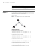
Network requirements
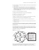
As shown in Figure 71, the masks of all the IP addresses are 255.255.255.0. It is
required that all the hosts or Switch 8800 Family series routing switches can be
interconnected in pairs by static route configuration.
Network diagram
Figure 71 Network diagram for the static route configuration example
Configuration procedure
# Configure the static route for Switch A
[Switch A] ip route-static 1.1.3.0 255.255.255.0 1.1.2.2
[Switch A] ip route-static 1.1.4.0 255.255.255.0 1.1.2.2
[Switch A] ip route-static 1.1.5.0 255.255.255.0 1.1.2.2
# Configure the static route for Switch B
[Switch B] ip route-static 1.1.2.0 255.255.255.0 1.1.3.1
[Switch B] ip route-static 1.1.5.0 255.255.255.0 1.1.3.1
[Switch B] ip route-static 1.1.1.0 255.255.255.0 1.1.3.1
# Configure the static route for Switch C
[Switch C] ip route-static 1.1.1.0 255.255.255.0 1.1.2.1
[Switch C] ip route-static 1.1.4.0 255.255.255.0 1.1.3.2
# Configure the default gateway of the Host A to be 1.1.1.2
# Configure the default gateway of the Host B to be 1.1.4.1
# Configure the default gateway of the Host C to be 1.1.5.2
Display the statistics of the routing table display ip routing-table statistics
Display the routing information about the VPN
instance
display ip routing-table vpn-instance
vpn-instance-name
Table 252 Display and debug the routing table
Operation Command
Host 1. 1.5. 1
1.1.5. 2/2 4
1.1.2. 2/2 4
1.1.2. 1/2 4
1.1.1. 2/2 4
Host 1. 1.1. 1
Host 1. 1.4. 2
1.1.3. 1/2 4
1.1.3. 2/2 4
1.1.4. 1/2 4
Switch A
Switch B
Switch C
A
C
B
Host 1. 1.5. 1
1.1.5. 2/2 4
1.1.2. 2/2 4
1.1.2. 1/2 4
1.1.1. 2/2 4
Host 1. 1.1. 1
Host 1. 1.4. 2
1.1.3. 1/2 4
1.1.3. 2/2 4
1.1.4. 1/2 4
Switch A
Switch B
Switch C
A
C
B