
3Com Switch 8800 Family Configuration Guide


432 CHAPTER 40: MULTICAST VLAN CONFIGURATION
Multicast VLAN
Configuration
Example
Network requirements
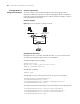
Configure a multicast VLAN, so that users in VLAN 2 and VLAN 3 receive multicast
flows through the multicast VLAN10.
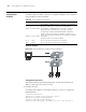
Network diagram
Figure 106 Network diagram for multicast VLAN configuration
Configuration procedure
Before performing the following configurations, you should configure the IP
addresses and connect the devices correctly.
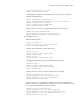
1 Configure Switch A
# Configure the IP address of the VLAN 2 interface to 168.10.1.1. Enable the
PIM-DM protocol.
<Switch A> system-view
System View: return to User View with Ctrl+Z.
[Switch A] multicast routing-enable
[Switch A] interface vlan-interface 2
[Switch A-Vlan-interface2] ip address 168.10.1.1 255.255.255.0
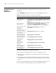
Tabl e 422 Device number and description
Device Description Requirement
Switch A Layer 3 switch
The IP address of VLAN 2 interface is 168.10.1.1. The port E1/1/1
belongs to VLAN 2 and is connected to the Workstation
The IP address of VLAN 10 interface is 168.20.1.1. The port
E1/1/10 belongs to VLAN 10 and is connected to Switch B
Configure layer 3 multicast PIM DM and IGMP on VLAN 10
Switch B Layer 2 switch
VLAN 2 contains the port E1/1/1 and VLAN 3 contains the port
E1/1/2. The ports E1/1/1 and E1/1/2 are connected to PC1 and PC2
respectively.
The port E1/1/10 is connected to Switch A.
PC 1 User 1 PC1 is connected to the port E1/1/1 of Switch B.
PC 2 User 2 PC2 is connected to the port E1/1/2 of Switch B.
PC 2PC 2PC 2PC 2
PC 1PC 1PC 1PC 1
Sw itc h A
PC 2PC 2PC 2
PC 1PC 1PC 1PC 1
Sw itc h A
WorkstationWorkstation
Sw itc h B
PC 2PC 2PC 2PC 2
PC 1PC 1PC 1PC 1
Sw itc h A
PC 2PC 2PC 2
PC 1PC 1PC 1PC 1
Sw itc h A
WorkstationWorkstation
Sw itc h B
PC 2PC 2PC 2PC 2
PC 1PC 1PC 1PC 1
Sw itc h A
PC 2PC 2PC 2PC 2
PC 1PC 1PC 1PC 1
Sw itc h A
PC 2PC 2PC 2
PC 1PC 1PC 1PC 1
Sw itc h A
PC 2PC 2PC 2
PC 1PC 1PC 1PC 1
Sw itc h A
WorkstationWorkstationWorkstationWorkstation
Sw itc h B