
3Com Switch 8800 Family Configuration Guide


438 CHAPTER 41: COMMON MULTICAST CONFIGURATION
Managed Multicast
Configuration Example
Network requirements
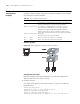
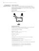
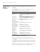
As shown in Figure 107, HostA and HostB join the multicast group. Layer 3
multicast is enabled on LSA, LSB, LSC and LSD. Managed multicast is enabled on
LSA and LSC. Because managed multicast combines multicast with 802.1x, 802.1x
must be enabled on LSA and LSC.
Network diagram
Figure 107 Network diagram for managed multicast
Configuration procedure
Managed multicast is a module combined with 802.1x, so you need to perform
the following configuration beside multicast configuration:
# Enable managed multicast globally.
<SW8800>system-view
System View: return to User View with Ctrl+Z.
[SW8800] ip managed-multicast
# Enable 802.1x globally.
[SW8800] dot1x
# Enable 802.1x on the controlled ports (the access ports for LSA and LSC).
[SW8800]interface GigabitEthernet2/1/1
[3Com-GigabitEthernet2/1/1] dot1x
[3Com-GigabitEthernet2/1/1] interface GigabitEthernet2/1/2
[3Com-GigabitEthernet2/1/2] dot1x
# Configure the authentication mode on the controlled ports to port-based mode.
[3Com-GigabitEthernet2/1/2] dot1x port-method portbased
[3Com-GigabitEthernet2/1/2] interface GigabitEthernet2/1/1
[3Com-GigabitEthernet2/1/1] dot1x port-method portbased
[3Com-GigabitEthernet2/1/1] quit
LSD
LSB
LSC
LSA
HostA HostB
VL AN1 1 VL AN12
VL AN1 0
VL AN1 0
VL AN1 1
VL AN1 2
VL AN1 2 VL AN1 0
VL AN1 1
LSD
LSB
LSC
LSA
HostB
VL AN1 1 VL AN12
VL AN1 0
VL AN1 0
VL AN1 1
VL AN1 2
VL AN1 2 VL AN1 0
VL AN1 1
Host
A
LSD
LSB
LSC
LSA
HostA HostB
VL AN1 1 VL AN12
VL AN1 0
VL AN1 0
VL AN1 1
VL AN1 2
VL AN1 2 VL AN1 0
VL AN1 1
LSD
LSB
LSC
LSA
HostB
VL AN1 1 VL AN12
VL AN1 0
VL AN1 0
VL AN1 1
VL AN1 2
VL AN1 2 VL AN1 0
VL AN1 1
Host
A