
3Com Switch 8800 Family Configuration Guide

Introduction to IGMP Proxy 443
Description of IGMP proxy configuration
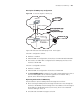
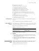
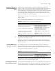
Figure 108 A schematic diagram of IGMP proxy
Figure 108 illustrates how IGMP proxy works. In this figure:
Switch B is configured as follows:
■ Multicast is enabled.
■ PIM and IGMP are configured on the interfaces of VLAN 100 and VLAN 200.
■ The interface of VLAN 100 is configured as the IGMP proxy interface of the
interface of VLAN 200.
Switch A is configured as follows:
■ Multicast is enabled.
■ PIM and IGMP are configured on the interface of VLAN 100.
■ The pim neighbor-policy command is executed in VLAN 100 interface view to
filter the PIM neighbors of the network segment 33.33.33.0/24. That is,
prevent Switch B from being the PIM neighbor.
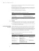
Operating mechanism of IGMP Proxy
The procedures to process IGMP join/leave messages are as follows:
■ After receiving an IGMP join/leave message sourced from a host through the
interface of VLAN 200, Switch B changes the source address of the message to
the IP address of VLAN 100 interface (33.33.33.2), which is the outbound
interface leading to Switch A.
■ Switch B sends the IGMP message to Switch A.
Vlan -interface 100
Vlan-interface 200
Normal group/Specific group
querying messages
IGMP join/leave messages
Vlan -interface 1
33.33.33.1
33.33.33.2
22.22.22.1
Switch A
Switch B
Џᴎ
䚼㔥㒰
Ṷ㔥㒰
VLAN interface 100
VLAN interface 200
VL AN in te rfa ce 1
33.33.33.1
33.33.33.2
22.22.22.1
Switch A
Switch B
Hos t
Exterior network
Leaf netw ork
Vlan -interface 100
Vlan-interface 200
Normal group/Specific group
querying messages
IGMP join/leave messages
Vlan -interface 1
33.33.33.1
33.33.33.2
22.22.22.1
Switch A
Switch B
Џᴎ
Vlan -interface 100
Vlan-interface 200
Normal group/Specific group
querying messages
IGMP join/leave messages
Vlan -interface 1
33.33.33.1
33.33.33.2
22.22.22.1
Switch A
Switch B
Џᴎ
䚼㔥㒰
Ṷ㔥㒰
VLAN interface 100
VLAN interface 200
VL AN in te rfa ce 1
33.33.33.1
33.33.33.2
22.22.22.1
Switch A
Switch B
Hos t
Exterior network
Leaf netw ork