
3Com Switch 8800 Family Configuration Guide


452 CHAPTER 42: IGMP CONFIGURATION
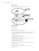
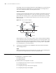
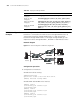
Network diagram
Figure 109 Network diagram for IGMP proxy configuration
Configuration steps
1 Configure Switch B.
# Enable multicast.
<SwitchB>system-view
System View: return to User View with Ctrl+Z.
[SwitchB] multicast routing-enable
# Create VLAN 200 and VLAN 100. Add related ports to the corresponding VLANs.
Enable IGMP and PIM-DM for the interfaces on Vlan-interface200 and
Vlan-interface 100.
[SwitchB]interface vlan-interface 200
[SwitchB-Vlan-interface 200] ip address 22.22.22.1 24
[SwitchB-Vlan-interface 200] igmp enable
[SwitchB-Vlan-interface 200] pim dm
[SwitchB-Vlan-interface 200] igmp host-join 224.0.1.1 port Ethernet 3/0/8
[SwitchB] interface vlan-interface 100
[SwitchB-Vlan-interface 100] ip address 33.33.33.2 24
[SwitchB-Vlan-interface 100] igmp enable
[SwitchB-Vlan-interface 100] pim dm
[SwitchB-Vlan-interface 100] quit
# Configure the interface of VLAN 100 to be the IGMP proxy interface of the
interface of VLAN 200.
[SwitchB] interface vlan-interface 200
[SwitchB-Vlan-interface 200] igmp proxy Vlan-interface 100
2 Configure Switch A.
Vlan -interface 100
Vlan-interface 200
Normal group/Specific group
querying messages
IGMP join/leave messages
Vlan -interface 1
33.33.33.1
33.33.33.2
22.22.22.1
Switch A
Switch B
Џᴎ
䚼㔥㒰
Ṷ㔥㒰
VLAN interface 100
VLAN interface 200
VL AN i nte rfa ce 1
33.33.33.1
33.33.33.2
22.22.22.1
Switch A
Switch B
Rec eiv er
Exterior netw ork
Leaf netw ork
Vlan -interface 100
Vlan-interface 200
Normal group/Specific group
querying messages
IGMP join/leave messages
Vlan -interface 1
33.33.33.1
33.33.33.2
22.22.22.1
Switch A
Switch B
Џᴎ
Vlan -interface 100
Vlan-interface 200
Normal group/Specific group
querying messages
IGMP join/leave messages
Vlan -interface 1
33.33.33.1
33.33.33.2
22.22.22.1
Switch A
Switch B
Џᴎ
䚼㔥㒰
Ṷ㔥㒰
VLAN interface 100
VLAN interface 200
VL AN i nte rfa ce 1
33.33.33.1
33.33.33.2
22.22.22.1
Switch A
Switch B
Rec eiv er
Exterior netw ork
Leaf netw ork