
3Com Switch 8800 Family Configuration Guide

Typical BGP/MPLS VPN Configuration Example 581
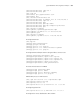
[ASBR-PE2-bgp] peer 20 route-policy rtp-ibgp export
[ASBR-PE2-bgp] peer 202.200.1.2 group 20
[ASBR-PE2-bgp] peer 202.200.1.2 connect-interface loopback0
Hierarchical BGP/MPLS
VPN Configuration
Example
Network requirements
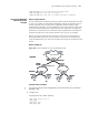
For those VPNs that have distinct hierarchy, an MPLS VPN covering a province and
its cities, for example, incorporating the backbone network at the province level
and the networks at the city level into a single MPLS VPN will impose a high
requirement in performance on the equipment on the entire network, in the event
that the network topology size is large. However, the requirement in equipment
performance can become lower if this MPLS VPN is separated into two VPNs, the
network at the province level and the network at the city level, for example.
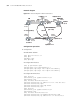
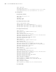
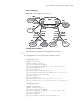
SPE acts as a PE on the network at the province level, and is connected with a
downstream MPLS VPN at the city level. UPE acts as a PE on the network at the
city level and provide access service for the VPN clients which are normally low-end
routers.
Network diagram
Figure 140 Network diagram for hierarchical BGP/MPLS VPN
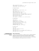
Configuration procedure
n
This case only illustrates the configurations concerned with PEs in a hierarchical
BGP/MPLS VPN.
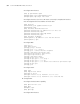
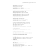
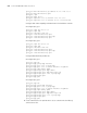
1 Configure SPE
# Configure the basic MPLS capability.
[SPE] mpls lsr-id 1.0.0.2
[SPE] mpls
[SPE-mpls] quit
[SPE] mpls ldp
MPLS
偼ᑆ㔥
PE
PE
SPE
Upper VPN
Lower VPN
UPE
CE
CE
CE CE
VPN1 Site1 VPN2 Site1
VPN1 Site1
VPN2 Site1
UPE
VLAN2 01
10. 0.0. 1/ 8
VLAN3 01
10.0.0.2/8
Loo pb ac k0 :1 0.0. 0. 2
Loo pb ac k0 :1. 0.0.1
MPLS backbone
PE
PE
SPE
UPE
CE
CE
CE CE
VPN1 Site1 VPN2 Site1
VPN1 Site1
VPN2 Site1
UPE
VLAN2 01
10. 0.0. 1/ 8
VLAN3 01
10.0.0.2/8
Loo pb ac k0 :1 0.0. 0. 2