
3Com Switch 8800 Family Configuration Guide

584 CHAPTER 49: BGP/MPLS VPN CONFIGURATION
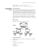
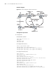
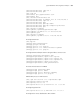
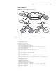
Network diagram
Figure 141 Network diagram for OSPF multi-instance
Configuration procedure
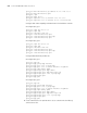
1 Configure PE1
# Enable MPLS and LDP.
[PE1] mpls lsr-id 50.1.1.1
[PE1] mpls
[PE1-mpls] quit
[PE1] mpls ldp
# Configure VPN-instance.
[PE1] ip vpn-instance vpn1
[PE1-vpn-vpn1] route-distinguisher 2:1
[PE1-vpn-vpn1] vpn-target 100:1 export-extcommunity
[PE1-vpn-vpn1] vpn-target 100:1 import-extcommunity
# Configure VLAN interface.
[PE1] vlan 203
[PE1-vlan203] port gigabitethernet 2/1/3
[PE1-vlan203] quit
[PE1] interface Vlan-interface 203
[PE1-Vlan-interface203] ip address 168.1.12.1 255.255.255.0
[PE1-Vlan-interface203] mpls
[PE1-Vlan-interface203] mpls ldp enable
[PE1-Vlan-interface203] quit
[PE1] vlan 201
[PE1-vlan201] port gigabitethernet 2/1/1
[PE1-vlan201] quit
[PE1] interface Vlan-interface 201
[PE1-Vlan-interface201] ip binding vpn-instance vpn1
[PE1-Vlan-interface201] ip address 10.1.1.2 255.255.255.0
CE1
10.10.10.10
CE2
20.20.20.20
12.1.1.0/24
PE1
PE3
3.3.3.3
PE2
2.2.2.2
VLAN201
10.1.1.1/24
(168.1.1.0/24)
20.2.1.0/24
VLAN202
12.1.1.1/24
MPLS VPN Backbone
LoopBack0: 1.1.1.1
LoopBack0: 2.2.2.2
LoopBack0: 3.3.3.3
VLAN201
10.1.1.2/24
VLAN203
168.1.12.1/24
VLAN202
168.1.13.1/24
(backdoor)
sham link
LoopBack1:
50.1.1.1
LoopBack1:50.1.1.2
LoopBack1:
50.1.1.3
1.1.1.1
VLAN203
168.1.12.2/24
VLAN202
168.1.13.2/24
VLAN202
168.1.23.2/24
VLAN201
168.1.23.1/24
VLAN201
20.1.1.2/24
VLAN201
20.1.1.1/24
VLAN202
12.1.1.2/24