
3Com Switch 8800 Family Configuration Guide

606 CHAPTER 50: CARD INTERMIXING FOR MPLS SUPPORT
n
■ The source port joins in the corresponding VLAN automatically after the
configuration of intermixing redirection, and the source port leaves the
corresponding VLAN automatically after the intermixing redirection is deleted.
■ When using the VPLS intermixing redirection command, you have to enable
join-vlan explicitly.
■ When using the VLL VPN intermixing redirection command, you must not
enable the QinQ function on the source port and destination port.
Typical Networking
Example
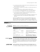
Network requirements
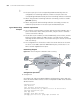
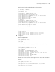
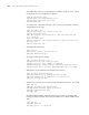
■ CE1 and CE3 constitute VPN A, and CE2 and CE4 constitute VPN B. In PE1, a
port of an interface card is shared, and in PE2, a Layer 2 switch is shared to
connect with the host directly.
■ The PE devices (PE1 and PE2) are Switch 8800 Family series switches, and the
PE devices need to support the MPLS function. CE1 and CE2 are common
mid-range and low-end routers. CE3 and CE4 are Layer 2 switches connected
with users directly.
■ The configurations of the interface cards of the two PE devices are the same.
On slot3 is a non-MPLS card with 100M Ethernet ports, and on Slot 2 is an
MPLS card with Gigabit Ethernet ports.
Networking diagram
Figure 145 Network diagram for BGP/MPLS VPN intermixing
Configuration procedure
1 Configure CE1
# Configure CE1 and CE2 as EBGP neighbors and import direct routes and static
routes So that the VPN user routes of CE1 are imported into BGP routes and then
advertised to PE1.
<CE1>system-view
[CE1] vlan 211
[CE1] interface vlan-interface 211
[CE1-vlan-interface211] ip address 10.10.10.10 255.255.255.0
[CE1-vlan-interface211] quit
[CE1] bgp 65410
[CE1-bgp] group vpna external
[CE1-bgp] peer 10.10.10.1 group vpna as-number 100
PE
PE 2
loopback0 1.1.1.1/32
vlan 100
CE2
CE1
CE3
CE4
vlan 1 00
loopback0 2.2.2.2/32
vlan 1 0
vlan 2 0
vlan 1 0
vlan 2 0
vlan 2 00
vlan 300
3
MPLSNetwork
PE 1
PE 2
loopback0 1.1.1.1/32
vlan 100
CE2
CE1
CE3
CE4
vlan 1 00
loopback0 2.2.2.2/32
vlan 1 0
vlan 2 0
vlan 1 0
vlan 2 0
vlan 2 00
vlan 300
P
MPLSNetwork
PE
PE 2
loopback0 1.1.1.1/32
vlan 100
CE2
CE1
CE3
CE4
vlan 1 00
loopback0 2.2.2.2/32
vlan 1 0
vlan 2 0
vlan 1 0
vlan 2 0
vlan 2 00
vlan 300
3
MPLSNetwork
PE
1
PE 2
Loopback0 1.1.1.1/32
VLAN 100
CE2
CE1
CE3
CE4
VLAN100
Loopback0 2.2.2.2/32
VLAN
10
VLAN 20
VLAN 10
VLAN 20
VLAN 300
VLAN 200
P
MPLS Netw ork
VLAN 211
PE
PE 2
loopback0 1.1.1.1/32
vlan 100
CE2
CE1
CE3
CE4
vlan 1 00
loopback0 2.2.2.2/32
vlan 1 0
vlan 2 0
vlan 1 0
vlan 2 0
vlan 2 00
vlan 300
3
MPLSNetwork
PE 1
PE 2
loopback0 1.1.1.1/32
vlan 100
CE2
CE1
CE3
CE4
vlan 1 00
loopback0 2.2.2.2/32
vlan 1 0
vlan 2 0
vlan 1 0
vlan 2 0
vlan 2 00
vlan 300
P
MPLSNetwork
PE
PE 2
loopback0 1.1.1.1/32
vlan 100
CE2
CE1
CE3
CE4
vlan 1 00
loopback0 2.2.2.2/32
vlan 1 0
vlan 2 0
vlan 1 0
vlan 2 0
vlan 2 00
vlan 300
3
MPLSNetwork
PE
1
PE 2
Loopback0 1.1.1.1/32
VLAN 100
CE2
CE1
CE3
CE4
VLAN100
Loopback0 2.2.2.2/32
VLAN
10
VLAN 20
VLAN 10
VLAN 20
VLAN 300
VLAN 200
P
MPLS Netw ork
VLAN 211