
3Com Switch 8800 Family Configuration Guide

VPLS Basic Configuration Example 647
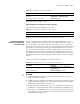
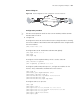
Network diagram
Figure 155 Network diagram for VPLS configuration of back-to back PEs
Configuration procedure
n
The VPLS service processor card is on slot 5 on PE1 and PE2, and the common
interface card is on slot 4.
1 Configure PE1
# Configure the Router ID used to advertise OSPF routing information. Generally,
the interface address of both MPLS LSR-ID and Loopback0 can be configured with
the same IP address.
[PE1] router id 5.6.7.8
# Configure MPLS LSI-ID. Enable MPLS and MPLS LDP globally.
[PE1] mpls lsr-id 5.6.7.8
[PE1] mpls
[PE1] mpls ldp
# Configure a 32-bit Loopback address, which is used to create LSP.
[PE1] interface loopback0
[PE1 -LoopBack0] ip address 5.6.7.8 32
# Configure a public VLAN, add a port to it, configure an IP address for the
interface. Then, enable MPLS and MPLS LDP on the interface.
[PE1] vlan 10
[PE1-vlan10] port GigabitEthernet 4/1/1
[PE1-vlan10] interface vlan 10
[PE1-vlan-interface10] ip address 10.10.10.10 24
[PE1-vlan-interface10] mpls
[PE1-vlan-interface10] mpls ldp enable
# Configure OSPF to set up routes.
[PE1] ospf
[PE1-ospf-1] area 0
[PE1-ospf-1-area-0.0.0.0] network 5.6.7.8 0.0.0.0
[PE1-ospf-1-area-0.0.0.0] network 10.10.10.10 0.0.0.255
[PE1-ospf-1-area-0.0.0.0] quit
[PE1-ospf-1] import-route direct
[PE1-ospf-1] quit
PE2 CE2
VPN 1
CE1
VPN 1
PE 1
VL AN 10 0
E6 /1/48
5.6.7.8
1. 2. 3. 4
VLAN 100
E6/1/48
VLAN 10
g4/1/1
VLAN 10
g4/1/1
10.10.10.10/24
10.10.10.11/24
VLAN 10
G4/1/1
VLAN 10
G4/1/1
10.10.10.10/24
10.10.10.11/24
PE2 CE2
VPN 1
CE1
VPN 1
PE 1
VL AN 10 0
E6 /1/48
5.6.7.8
1. 2. 3. 4
VLAN 100
E6/1/48
VLAN 10
g4/1/1
VLAN 10
g4/1/1
10.10.10.10/24
10.10.10.11/24
VLAN 10
G4/1/1
VLAN 10
G4/1/1
10.10.10.10/24
10.10.10.11/24
PE2 CE2
VPN 1
CE1
VPN 1
PE 1
VL AN 10 0
E6 /1/48
5.6.7.8
1. 2. 3. 4
VLAN 100
E6/1/48
VLAN 10
g4/1/1
VLAN 10
g4/1/1
10.10.10.10/24
10.10.10.11/24
VLAN 10
G4/1/1
VLAN 10
G4/1/1
10.10.10.10/24
10.10.10.11/24
PE2 CE2
VPN 1
CE1
VPN 1
PE 1
VL AN 10 0
E6 /1/48
5.6.7.8
1. 2. 3. 4
VLAN 100
E6/1/48
VLAN 10
g4/1/1
VLAN 10
g4/1/1
10.10.10.10/24
10.10.10.11/24
VLAN 10
G4/1/1
VLAN 10
G4/1/1
10.10.10.10/24
10.10.10.11/24
PE2 CE2
VPN 1
CE1
VPN 1
PE 1
VL AN 10 0
E6 /1/48
5.6.7.8
1. 2. 3. 4
VLAN 100
E6/1/48
VLAN 10
g4/1/1
VLAN 10
g4/1/1
10.10.10.10/24
10.10.10.11/24
VLAN 10
G4/1/1
VLAN 10
G4/1/1
10.10.10.10/24
10.10.10.11/24
PE2 CE2
VPN 1
CE1
VPN 1
PE 1
VL AN 10 0
E6 /1/48
5.6.7.8
1. 2. 3. 4
VLAN 100
E6/1/48
VLAN 10
g4/1/1
VLAN 10
g4/1/1
10.10.10.10/24
10.10.10.11/24
VLAN 10
G4/1/1
VLAN 10
G4/1/1
10.10.10.10/24
10.10.10.11/24
PE2 CE2
VPN 1
CE1
VPN 1
PE 1
VL AN 10 0
E6 /1/48
5.6.7.8
1. 2. 3. 4
VLAN 100
E6/1/48
VLAN 10
g4/1/1
VLAN 10
g4/1/1
10.10.10.10/24
10.10.10.11/24
VLAN 10
G4/1/1
VLAN 10
G4/1/1
10.10.10.10/24
10.10.10.11/24
PE2 CE2
VPN 1
CE1
VPN 1
PE 1
VL AN 10 0
E6 /1/48
5.6.7.8
1. 2. 3. 4
VLAN 100
E6/1/48
VLAN 10
g4/1/1
VLAN 10
g4/1/1
10.10.10.10/24
10.10.10.11/24
VLAN 10
G4/1/1
VLAN 10
G4/1/1
10.10.10.10/24
10.10.10.11/24