
3Com Switch 8800 Family Configuration Guide


NTP Configuration Example 765
The above examples configured 3Com4 and 3Com1 to listen to the broadcast
through Vlan-interface2, 3Com3 to broadcast packets from Vlan-interface2. Since
3Com1 and 3Com3 are not located on the same segment, they cannot receive any
broadcast packets from 3Com3, while 3Com4 is synchronized by 3Com3 after
receiving its broadcast packet.
After the synchronization, you can find the state of 3Com4 as follows:
[3Com4] display ntp-service status
clock status: synchronized
clock stratum: 3
reference clock ID: LOCAL(0)
nominal frequency: 100.0000 Hz
actual frequency: 100.0000 Hz
clock precision: 2^17
clock offset: 0.0000 ms
root delay: 0.00 ms
root dispersion: 10.94 ms
peer dispersion: 10.00 ms
reference time: 20:54:25.156 UTC Mar 7 2002(C0325201.2811A112)
By this time, 3Com4 has been synchronized by 3Com3 and it is at stratum 3,
higher than 3Com3 by 1.
Display the status of 3Com4 sessions and you will see 3Com4 has been connected
to 3Com3.
[3Com2] display ntp-service sessions
source reference stra reach poll now offset delay disper
[12345]127.127.1.0 LOCAL(0) 7 377 64 57 0.0 0.0 1.0
[5]1.0.1.11 LOCAL(0) 3 0 64 - 0.0 0.0 0.0
[5]128.108.22.44 0.0.0.0 16 0 64 - 0.0 0.0 0.0
note: 1 source(master),2 source(peer),3 selected,4 candidate,5 configured
Configure NTP Multicast
Mode
Network requirements
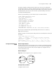
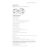
3Com3 sets the local clock as the master clock at stratum 2 and multicast packets
from Vlan-interface2. Set 3Com4 and 3Com1 to receive multicast messages from
their respective Vlan-interface2. (Note: 3Com3 supports to configure the local
clock as the master clock)
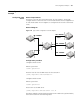
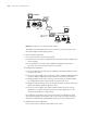
Network diagram
Figure 178 Network diagram for NTP configuration example
Configuration procedure
Configure Switch 3Com3:
......
Vlan - interface2:
1.0.1.11
3Com-0
3Com-1
3Com-2
3Com-3
3Com-4
3Com-5
Vlan - interface2:
1.0.1.12
Vlan - interface2:
3.0.1.31
Vlan - interface2:
3.0.1.32
Vlan - interface2:
3.0.1.33
1.0.1.2 3.0.1.2