3Com® Switch 8800 Family Firewall Configuration and Command Reference Guide Switch 8807 Switch 8810 Switch 8814 www.3Com.com Part No. 10015596, Rev.
3Com Corporation 350 Campus Drive Marlborough, MA USA 01752-3064 Copyright © 2006-2007, 3Com Corporation. All rights reserved. No part of this documentation may be reproduced in any form or by any means or used to make any derivative work (such as translation, transformation, or adaptation) without written permission from 3Com Corporation.
CONTENTS ABOUT THIS GUIDE Conventions 7 Related Documentation 8 1 SWITCH 8800 FIREWALL MODULE 2 FIREWALL CONFIGURATION Firewall Configuration 13 Displaying Information about the Firewall Module 3 15 NETWORK SECURITY CONFIGURATION Introduction to the Network Security Features 17 Hierarchical Command Line Protection 18 RADIUS-Based AAA 18 Packet Filter and Firewall 18 Security Authentication before Route Information Exchange 4 21 AAA AND RADIUS/HWTACACS PROTOCOL CONFIGURATION Overview 23 Configuri
NAT Configuration 82 Displaying and Debugging NAT 87 NAT Configuration Example 87 Troubleshooting NAT Configuration 90 7 FIREWALL CONFIGURATION Introduction to Firewall 93 Configuring Packet Filter Firewall 97 Configuring ASPF 104 Black List 110 MAC and IP Address Binding 115 Security Zone Configuration 119 8 TRANSPARENT FIREWALL Transparent Firewall Overview 121 Configuring Transparent Firewall 125 Displaying and Debugging Transparent Firewall 128 Transparent Firewall Configuration Example 129 9 WEB
12 RELIABILITY OVERVIEW Introduction to Reliability 13 189 VRRP CONFIGURATIONS Introduction to VRRP 191 Configuring VRRP 192 Displaying and Debugging VRRP 197 VRRP Configuration Examples 197 VRRP Troubleshooting 207 14 FIREWALL CONFIGURATION COMMANDS Firewall Configuration Commands 15 209 AAA/RADIUS/HWTACACS CONFIGURATION COMMANDS AAA Configuration Commands 215 RADIUS Protocol Configuration Commands 231 HWTACACS Configuration Commands 257 16 ACCESS CONTROL LIST CONFIGURATION COMMANDS ACL Configur
Conventions 7 ABOUT THIS GUIDE This guide describes the 3Com® Switch 8800 and how to install hardware, configure and boot software, and maintain software and hardware. This guide also provides troubleshooting and support information for your switch. This guide is intended for Qualified Service personnel who are responsible for configuring, using, and managing the switches.
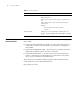
ABOUT THIS GUIDE Table 2 Text Conventions Convention Description Words in italics Italics are used to: Emphasize a point. Denote a new term at the place where it is defined in the text. Identify menu names, menu commands, and software button names. Examples: From the Help menu, select Contents. Click OK. Words in bold Related Documentation Boldface type is used to highlight command names. For example, “Use the display user-interface command to...
1 SWITCH 8800 FIREWALL MODULE This chapter describes the Firewall Module (3C17546), which is available for the Switch 8800. The SW8800 Firewall Module provides an affordable stateful security firewall designed for the needs of medium-size enterprises. Enterprises are accelerating their deployments of stateful firewalls to protect their organizations from unwanted intrusions from attackers from both outside (e.g. from the Internet), and from internal attack.
CHAPTER 1: SWITCH 8800 FIREWALL MODULE Table 1 Firewall Module Functions Attribute Description Authentication, authorization and accounting service RADIUS HWTACACS CHAP authentication PAP authentication Domain authentication Firewall Packet filtering Access control list on the basis of interface Access control list on the basis of time period ASPF status firewall Anti-attack features: Land, Smurf, Fraggle, WinNuke, Ping of Death, Tear Drop, IP Spoofing, SYN Flood, ICMP Flood, UDP Flood, ARP spoofin
Table 1 Firewall Module Functions Attribute Description Initiating connection to the specified LNS according to the full user name and domain name of the VPN user L2TP VPN VPN Distributing addresses for VPN users LCP re-negotiation and CHAP re-authentication L2TP multi-instance GRE VPN Use Tunnel technology to encapsulate and decapsulate data packets at both sides of the Tunnel Ethernet_II LAN protocol Network interconnection Ethernet_SNAP VLAN Data link layer protocol PPP PPPoE ARP Static doma
CHAPTER 1: SWITCH 8800 FIREWALL MODULE Table 1 Firewall Module Functions Attribute Description Local configuration through the Console interface Remote configuration through the AUX interface Local or remote configuration through Telnet or SSH Configuring the module through the Switch 8800 Family switch Configuring hierarchical protection commands to make sure non-authenticated users cannot configure the device Providing detailed debugging information to diagnose network failure Configuration managem
FIREWALL CONFIGURATION 2 Firewall Configuration Configuring the Interface Aggregation To make the Switch 8800 Family routing switch and firewall module work together, you need to configure the firewall on the switch by: ■ “Configuring the Interface Aggregation” ■ “Creating the Firewall Module” ■ “Specifying the Layer 3 Interface Connecting the Switch and the Firewall” ■ “Specifying the VLAN Protected by the Firewall” ■ “Mapping the Firewall to the Firewall Module” ■ “Logging into the Firewall
CHAPTER 2: FIREWALL CONFIGURATION Table 3 Create the Firewall Operation Command Remove the SecBlade undo secblade sec-mod-name By default, the Firewall is not created. Specifying the Layer 3 Interface Connecting the Switch and the Firewall To enable the Firewall and Switch 8800 Family switch to communicate at Layer 3, specify the Layer 3 interface connecting the switch and the firewall. Perform the following configuration in SecBlade view of the switch.
Displaying Information about the Firewall Module 15 Table 7 Log into the Firewall Configuring Default Login User Function Operation Command Log into the Firewall secblade slot slot-number For login convenience, a user whose name and password are both SecBlade is created in the Firewall module. You can use this user name and password to log into the Firewall. Perform the following configuration in SecBlade system view.
CHAPTER 2: FIREWALL CONFIGURATION
NETWORK SECURITY CONFIGURATION 3 n Introduction to the Network Security Features The content below applies to the Firewall modue, so the command views in this document apply only to the module and not the Switch 8800 Family switches. A security gateway must be able to withstand the various malicious attacks from the public network. On the other hand, the accidental but destructive access of the user may also result in significant performance decrease and even the operation failure.
CHAPTER 3: NETWORK SECURITY CONFIGURATION The following chapters describe how to configure AAA and RADIUS, user password, firewall and packet filtering. Refer to the VPN part of this manual for IPSec/IKE configuration; refer to “NAT Configuration” for address translation configuration. Hierarchical Command Line Protection The system command lines are protected in a hierarchical way. In this approach, the command lines are divided into four levels: visit, monitor, system, and manage.
Packet Filter and Firewall 19 Figure 1 A firewall separating the intranet from the Internet Internet Firewall Ethernet PC PC 6HUYHU PC The firewall is not only applied to the Internet connection, but also used to protect the mainframe and crucial resources like data on the intranet of the organization. Access to the protected data should be permitted by the firewall, even if the access is initiated from the organization.
CHAPTER 3: NETWORK SECURITY CONFIGURATION ■ Packet filter: Such a firewall filters each packet depending on the items that defined by the user. For example, it compares the packets with the defined rules in source and destination addresses for a match. A packet filter neither considers the status of sessions, nor analyzes the data.
Security Authentication before Route Information Exchange 21 Figure 2 Packet filtering elements Most packet filter systems do not make any operations on data itself or make contents-based filtering. ACL Before the system can filter the packets, you should configure some rules in ACLs to specify the types of packets allowed or denied. A user should configure an ACL according to the security policy and apply it to a particular interface or the whole equipment.
CHAPTER 3: NETWORK SECURITY CONFIGURATION
4 AAA AND RADIUS/HWTACACS PROTOCOL CONFIGURATION Overview Introduction to AAA Authentication, Authorization and Accounting (AAA) provide a uniform framework used for configuring these three security functions to implement the network security management.
CHAPTER 4: AAA AND RADIUS/HWTACACS PROTOCOL CONFIGURATION Accounting AAA supports the following accounting methods: n ■ None accounting: no accounting required. ■ Remote accounting: conducted through a RADIUS server or TACACS server. Currently, security gateway supports accounting of PPP users and Telnet users only, but it does not support real-time accounting of Telnet users. AAA usually utilizes a Client/Server model, where the client controls user access and the server stores user information.
Overview 25 Figure 3 Components of RADIUS server RADIUS Server Users Dictionary Clients In addition, RADIUS servers can act as the client of some other AAA server to provide the proxy authentication or accounting service. They support multiple user authentication methods, such as PPP-based PAP, CHAP and UNIX-based login. Basic message exchange procedures in RADIUS In most cases, user authentication using a RADIUS server always involves a device that can provide the proxy function, such as the NAS.
CHAPTER 4: AAA AND RADIUS/HWTACACS PROTOCOL CONFIGURATION response (Access-Accept) containing the information of user’s right. If the authentication fails, it returns an Access-Reject message. 4 The RADIUS client acts on the returned authentication result to accept or deny the user. If it is allowed to accept the user, the RADIUS client sends an accounting start request (Accounting-Request) to the RADIUS server, with the value of Status-Type being "start".
Overview 27 Table 10 Code values Code Packet type Description 3 Access-Reject The packet is transmitted by the server to the client. If any attribute value carried in the Access-Request is unacceptable, the server rejects the user and sends back an Access-Reject response. Accounting-Request The packet carries user information and is transmitted by the client to the server to request the server to start accounting.
CHAPTER 4: AAA AND RADIUS/HWTACACS PROTOCOL CONFIGURATION The RADIUS protocol is extensible. The Attribute 26 (Vender-Specific) defined in it allows a user to define an extended attribute.
Overview 29 Figure 7 Network diagram for a typical HWTACACS application Terminal user TACACS server 129.7.66.66 ISDN \PSTN Dialup user Quidway HWTACACS client TACACS server 129.7.66.67 Basic message exchange procedures in HWACACS For example, use HWTACACS to implement authentication, authorization, and accounting for a telnet user.
CHAPTER 4: AAA AND RADIUS/HWTACACS PROTOCOL CONFIGURATION Figure 8 The AAA implementation procedures for a telnet user User HWTACACS HWTACACS Client Server User logs in Authentication Start Request packet Authentication response packet , requesting for the user name Request User for the user name User enters the user name Authentication continuance packet carrying the user name Authentication response packet , requesting for the password Request User for the password User enters the password
Configuring AAA 31 user named userid@isp-name, the security gateway system considers the userid part as the username for authentication and the isp-name part as the domain name. The purpose of introducing ISP domain settings is to support the multi-ISP application environment, where one access device might access users of different ISPs. Because the attributes of ISP users, such as username and password formats, can be different, you must differentiate them through setting ISP domains.
CHAPTER 4: AAA AND RADIUS/HWTACACS PROTOCOL CONFIGURATION Table 14 Configure the related attributes of the ISP domain Operation Command Configure an AAA scheme for the domain. scheme { radius-scheme radius-scheme-name [ local ] | hwtacacs-scheme hwtacacs-scheme-name [ local ] | local | none } Restore the default AAA scheme. undo scheme [ radius-scheme | hwtacacs-scheme | none ] The default AAA scheme is local.
Configuring AAA ■ 33 For DVPN services At present, only RADIUS, local and RADIUS-local support authentication and authorization, and only RADIUS supports accounting. Perform the following configuration in ISP domain view. Table 15 Configure the related ISP domain attributes Operation Command Configure an authentication scheme for the domain.
CHAPTER 4: AAA AND RADIUS/HWTACACS PROTOCOL CONFIGURATION By default, an ISP domain is active when it is created. Setting an access limit You can specify the maximum number of users that an ISP domain can accommodate by setting an access limit. Perform the following configuration in ISP domain view. Table 17 Configure an access limit Operation Command Set an access limit to limit the number of users access-limit { disable | enable that the domain can accommodate.
Configuring AAA 35 Perform the following configuration in ISP domain view. Table 19 Define an IP address pool for PPP domain users Operation Command Define an IP address pool for allocating addresses to PPP users. ip pool pool-number low-ip-address [ high-ip-address ] Delete the specified address pool. undo ip pool pool-number By default, no address pool is configured.
CHAPTER 4: AAA AND RADIUS/HWTACACS PROTOCOL CONFIGURATION Perform the following configuration in system view Table 20 Create/delete a local user and the relevant properties Operation Command Add a local user. local-user user-name Delete a local user or the service type of the local user. undo local-user user-name [ service-type | level ] Delete all local users or all local users of a specific service type.
Configuring the RADIUS Protocol 37 Table 22 Set/remove the attributes concerned with a specified user Operation Command Set the attributes of callback number and call number of PPP users. service-type ppp [ callback-nocheck | callback-number callback-number | call-number call-number [ subcall-number ] ] Restore the default callback number and call number of PPP users. undo service-type ppp [ callback-nocheck | callback-number | call-number ] By default, no service is authorized to users.
CHAPTER 4: AAA AND RADIUS/HWTACACS PROTOCOL CONFIGURATION Among these tasks, creating a RADIUS scheme and configuring RADIUS authentication/authorization servers are required, while other tasks are optional at your discretion. Creating a RADIUS Scheme As mentioned earlier, the RADIUS protocol is configured scheme by scheme. Therefore, before performing other RADIUS protocol configurations, you must create a RADIUS scheme and enter its view.
Configuring the RADIUS Protocol 39 Table 24 Configure IP address and port number of RADIUS authentication/authorization servers Operation Command Restore IP address and port number of the secondary RADIUS authentication/authorization server to the default values. undo secondary authentication As the authorization information from the RADIUS server is sent to RADIUS clients in authentication response packets, so you do not need to specify a separate authorization server.
CHAPTER 4: AAA AND RADIUS/HWTACACS PROTOCOL CONFIGURATION Configuring optional accounting If a user is configured with the accounting optional command, the device does not disconnect the user during the accounting even when it finds no available accounting server or fails to communicate with the accounting server. Perform the following configuration in RADIUS domain view. Table 26 Enable/disable optional accounting Operation Command Enable optional accounting.
Configuring the RADIUS Protocol 41 terminates a user connection if it receives no response after the number of transmitted real-time accounting requests exceeds the configured limit. You can use the following command to set the maximum number of real-time accounting request attempts. Perform the following configuration in RADIUS view. Table 28 Set the maximum number of real-time accounting request attempts Operation Command Set the maximum number of real-time accounting request attempts.
CHAPTER 4: AAA AND RADIUS/HWTACACS PROTOCOL CONFIGURATION Table 30 Set the maximum number of RADIUS request attempts Operation Command Set the maximum number of RADIUS request attempts. retry retry-times Restore the default maximum number of RADIUS request attempts. undo retry By default, a RADIUS request can be sent up to three times. Setting the Supported RADIUS Server Type You can use the following command to set the supported RADIUS server type.
Configuring the RADIUS Protocol 43 You can use the display radius command to view the server state in the RADIUS scheme. Setting Username Format Acceptable to RADIUS Server As mentioned above, the supplicants are generally named in userid@isp-name format. The part following "@" is the ISP domain name. 3Com Series Security Gateways will put the users into different ISP domains according to the domain names. However, some earlier RADIUS servers reject the username including ISP domain name.
CHAPTER 4: AAA AND RADIUS/HWTACACS PROTOCOL CONFIGURATION Table 35 Configure source address for the RADIUS packets sent by the NAS Operation Command Cancel the configured source address to be carried in the RADIUS packets sent by the NAS(System view). undo radius nas-ip You can use either command to bind a source address with the NAS. By default, no source address is specified and the source address of a packet is the address of the interface where it is sent.
Configuring the RADIUS Protocol 45 Table 38 Set a real-time accounting interval Operation Command Set a real-time accounting interval. timer realtime-accounting minutes Restore the default real-time accounting interval. undo timer realtime-accounting In the command, minutes represents the interval for realtime accounting and it must be a multiple of three.
CHAPTER 4: AAA AND RADIUS/HWTACACS PROTOCOL CONFIGURATION n When the local RADIUS authentication server function is enabled, the UDP port number for the authentication/authorization services must be 1645 and that for the accounting service must be 1646. The packet key password configured here must be the same with the authentication/authorization packet key password configured in the key authentication command in RADIUS view.
Configuring HWTACACS Protocol 47 If the HWTACACS scheme you specify does not exist, the system creates it and enters HWTACACS view. In HWTACACS view, you can configure the HWTACACS scheme. The system supports up to 128 HWTACACS schemes. You can only delete the schemes that are not being used. By default, no HWTACACS scheme exists. Configuring TACACS Authentication Servers Perform the following configuration in HWTACACS view.
CHAPTER 4: AAA AND RADIUS/HWTACACS PROTOCOL CONFIGURATION The primary and secondary authorization servers cannot use the same IP address. Otherwise, the system will prompt unsuccessful configuration. The default port number is 49. If you execute this command repeatedly, the new settings will replace the old settings. You can remove a server that cannot be removed otherwise, only when it is not used by any active TCP connection for sending authorization packets.
Configuring HWTACACS Protocol Configuring Source Address for HWTACACS Packets Sent by NAS 49 Perform the following configuration. Table 47 Configure the source address to be carried in HWTACACS packets sent by the NAS Operation Command Configure the source address to be carried in HWTACACS packets sent by the NAS(HWTACACS view). nas-ip ip-address Delete the configured source address to be carried in the HWTACACS packets sent by the NAS (HWTACACS view).
CHAPTER 4: AAA AND RADIUS/HWTACACS PROTOCOL CONFIGURATION Table 50 Set the unit of data flows destined for the TACACS server Operation Set the unit of data flows destined for the TACACS server. Restore the default unit of data flows destined for the TACACS server. Command data-flow-format data { byte | giga-byte | kilo-byte | mega-byte } data-flow-format packet { giga-packet | kilo-packet | mega-packet | one-packet } undo data-flow-format { data | packet } By default, data is sent in bytes.
Displaying and Debugging AAA and RADIUS/HWTACACS Protocols 51 Table 53 Set a real-time accounting interval Operation Command Restore the default real-time accounting interval. undo timer realtime-accounting The interval is in minutes and must be a multiple of 3. The setting of real-time accounting interval somewhat depends on the performance of the NAS and the TACACS server: a shorter interval requires higher device performance.
CHAPTER 4: AAA AND RADIUS/HWTACACS PROTOCOL CONFIGURATION Table 56 Display and debug the RADIUS protocol Operation Command Display the statistics on the local RADIUS authentication server. display local-server statistics Enable RADIUS packet debugging. debugging radius packet Disable RADIUS packet debugging. undo debugging radius packet Enable local RADIUS authentication server debugging.
AAA and RADIUS/HWTACACS Protocol Configuration Example 53 Connect the module to the RADIUS server (functions as both authentication and accounting servers) whose IP address is 10.0.0.1/24. On the module, set the shared keys both for packet exchange with the authentication server and with the accounting server as "expert". You can use a 3Com CAMS server as the RADIUS server.
CHAPTER 4: AAA AND RADIUS/HWTACACS PROTOCOL CONFIGURATION [SW8800] vlan [3Com-vlan30] [SW8800] vlan [3Com-vlan50] 30 quit 50 quit # Configure the IP address. [SW8800] interface vlan-interface 10 [3Com-Vlan-interface10] ip address 10.0.0.254 24 [3Com-Vlan-interface10] quit [SW8800] interface vlan-interface 30 [3Com-Vlan-interface30] ip address 30.0.0.1 24 [3Com-Vlan-interface30] quit # Configure the static route. [SW8800] ip route-static 0.0.0.0 0 30.0.0.
AAA and RADIUS/HWTACACS Protocol Configuration Example 55 # Add the sub-interface of the internal network to the trust zone. [secblade] firewall zone trust [secblade-zone-trust] add interface GigabitEthernet 0/0.1 [secblade-zone-trust] quit # Add the sub-interface of the external network to the untrust zone. [secblade] firewall zone untrust [secblade-zone-untrust] add interface GigabitEthernet 0/0.2 [secblade-zone-untrust] quit # Configure the static route. [secblade] ip route-static 10.0.0.0 24 30.0.0.
CHAPTER 4: AAA AND RADIUS/HWTACACS PROTOCOL CONFIGURATION Configuring FTP/Telnet User Local Authentication n Configuring local authentication for FTP users is similar to that for Telnet users. The following example is based on Telnet users. Network requirements Configure the module to authenticate the login Telnet users at the local (see Figure 10). Network diagram Figure 10 Network diagram for Telnet user local authentication Firewall S8800 Configuration procedure 1 Telnet User IP address: 10.0.
AAA and RADIUS/HWTACACS Protocol Configuration Example 57 # Configure the IP address. [SW8800] interface vlan-interface 10 [3Com-Vlan-interface10] ip address 10.0.0.254 24 [3Com-Vlan-interface10] quit [SW8800] interface vlan-interface 30 [3Com-Vlan-interface30] ip address 30.0.0.1 24 [3Com-Vlan-interface30] quit # Configure the static route. [SW8800] ip route-static 0.0.0.0 0 30.0.0.254 # Configure the aggregation of the module interfaces (the module resides in slot 2).
CHAPTER 4: AAA AND RADIUS/HWTACACS PROTOCOL CONFIGURATION [secblade] firewall zone trust [secblade-zone-trust] add interface GigabitEthernet 0/0.1 [secblade-zone-trust] quit # Add the sub-interface of the external network to the untrust zone. [secblade] firewall zone untrust [secblade-zone-untrust] add interface GigabitEthernet 0/0.2 [secblade-zone-untrust] quit # Configure the static route. [secblade] ip route-static 0.0.0.0 0 50.0.0.1 [secblade] ip route-static 10.0.0.0 24 30.0.0.
AAA and RADIUS/HWTACACS Protocol Configuration Example Network diagram Figure 11 Network diagram for remote RADIUS authentication on the Telnet user Configuration procedure 1 TACACS Server IP address: 10.0.0.1/24. Gateway: 10.0.0.254. 2 Telnet User IP address: 50.0.0.1/24. 3 Switch 8807 (SecBlade) # Divide VLANs. system-view [SW8800] vlan 10 [3Com-vlan10] quit [SW8800] vlan 30 [3Com-vlan30] quit [SW8800] vlan 50 [3Com-vlan50] quit # Configure the IP address.
CHAPTER 4: AAA AND RADIUS/HWTACACS PROTOCOL CONFIGURATION [SW8800] ip route-static 0.0.0.0 0 30.0.0.254 # Configure aggregation Firewall module interfaces (the module resides in slot 2). [SW8800] secblade aggregation slot 2 # Create SecBlade test. [SW8800] secblade test # Specify the the interface VLAN. [3Com-secblade-test] secblade-interface vlan-interface 30 # Set the protected VLAN. [3Com-secblade-test] security-vlan 50 # Map the module to the specified slot.
Troubleshooting AAA and RADIUS/HWTACACS Protocols 61 # Configure the Telnet user to use AAA authentication. [secblade] user-interface vty 0 4 [secblade-ui-vty0-4] authentication-mode scheme # Configure the RADIUS scheme. [secblade] hwtacacs scheme [secblade-hwtacacs-system] [secblade-hwtacacs-system] [secblade-hwtacacs-system] [secblade-hwtacacs-system] [secblade-hwtacacs-system] [secblade-hwtacacs-system] [secblade-hwtacacs-system] system primary authentication 10.0.0.1 49 primary accounting 10.0.0.
CHAPTER 4: AAA AND RADIUS/HWTACACS PROTOCOL CONFIGURATION ■ Symptom 2: RADIUS packets cannot reach the RADIUS server. Troubleshooting: Check that: 1 The communication links (at both physical and link layers) between the NAS and the RADIUS server work well. 2 The IP address of the RADIUS server is correctly configured on the NAS. 3 Authentication/Authorization and accounting UDP ports are set in consistency with the port numbers set on the RADIUS server.
Introduction to ACL 63 5 ACL CONFIGURATION Introduction to ACL ACL Overview Classification of ACL In order to filter data packets, a series of rules need to be configured on the security gateway to decide which data packets can pass. These rules are defined by ACL (Access Control List), which are a series of sequential rules consisting of the permit and the deny statements. The rules are described by source address, destination address and port number of data packets.
CHAPTER 5: ACL CONFIGURATION interface-based access control rules, put the rule configured with "any" behind, and arrange others according to configuration sequence. For advance access control rules, compare their source address wildcards first. If they are the same, compare their destination address wildcards. If they are also the same, compare their ranges of port number. Put those with smaller ranges before others.
sic ACL B a Basic ACL can only adopt source address information to serve as element for defining ACL rule. A basic ACL can be created and basic ACL view be entered by the above-mentioned ACL command. In basic ACL view, the rule of basic ACL can be created.
CHAPTER 5: ACL CONFIGURATION rule 1 deny logging Then, the ACL rule becomes: rule 1 deny source 1.1.1.1 0 logging The following command can be used to delete a basic ACL rule: undo rule rule-id [ source ] [ time-range ] [ logging ] [ fragment ] Parameter description: Advanced ACL ■ rule-id: Number of ACL rule, which should be an existing ACL rule number. If there is no parameter followed, the entire ACL rule will be deleted.
Introduction to ACL 67 means to add a new rule. In this case, the system will assign a number automatically for the ACL rule and add the new rule. ■ deny: Discard qualified data packet. ■ permit: Permit qualified data packet. ■ protocol: IP carried protocol type represented by name or number. The number range is from 1 to 255. The name can be gre, icmp, igmp, ip, ipinip, ospf, tcp, and udp. ■ source: Optional parameter, used to specify source address information of ACL rule.
CHAPTER 5: ACL CONFIGURATION ■ established: Compares all TCP packets with ACK and RST flags set, including SYN+ACK, ACK, FIN+ACK, RST and RST+ACK packets. ■ precedence: Optional parameter, according to which data packet can be filtered. A number ranging from 0 to 7 or a name. This keyword is mutually exclusive with the dscp keyword. ■ tos tos: Optional parameter. Data packet can be filtered according to service type field. A number ranging from 0 to 15 or a name.
Introduction to ACL 69 undo rule rule-id [ source ] [ destination ] [ source-port ] [ destination-port ] [ icmp-type ] [ dscp ] [ precedence ] [ tos ] [ time-range ] [ logging ] [ fragment ] Parameter description: ■ rule-id: Number of ACL rule, which should be an existing ACL rule number. If there is no parameter followed, the entire ACL rule will be deleted. Otherwise, only part of information related to the ACL rule will be deleted. ■ source: Optional parameter.
CHAPTER 5: ACL CONFIGURATION When specifying portnumber, part of common port numbers can use mnemonics to substitute actual numbers. The supported mnemonics are shown in the table below.
Introduction to ACL 71 Table 59 Port number mnemonics Protocol Mnemonics Meaning and actual value UDP biff Mail notify (512) bootpc Bootstrap Protocol Client (68) bootps Bootstrap Protocol Server (67) discard Discard (9) dns Domain Name Service (53) dnsix DNSIX Security Attribute Token Map (90) echo Echo (7) mobilip-ag MobileIP-Agent (434) mobilip-mn MobilIP-MN (435) nameserver Host Name Server (42) netbios-dgm NETBIOS Datagram Service (138) netbios-ns NETBIOS Name Service (137)
CHAPTER 5: ACL CONFIGURATION Table 60 Mnemonics of ICMP packet type Mnemonic Meaning echo Type=8, Code=0 echo-reply Type=0, Code=0 fragmentneed-DFset Type=3, Code=4 host-redirect Type=5, Code=1 host-tos-redirect Type=5, Code=3 host-unreachable Type=3, Code=1 information-reply Type=16,Code=0 information-request Type=15,Code=0 net-redirect Type=5, Code=0 net-tos-redirect Type=5, Code=2 net-unreachable Type=3, Code=0 parameter-problem Type=12,Code=0 port-unreachable Type=3, Code
Introduction to ACL 73 specified number to create a new rule. When the number is not specified, it means to add a new rule. In this case, the system will assign a number automatically for the ACL rule and add the new rule. ■ deny: Discards qualified data packet. ■ permit: Permits qualified data packet. ■ interface interface-type interface-number: Specifies the interface information of the packets. If no interface is specified, all interfaces can be matched. any represents all interfaces.
CHAPTER 5: ACL CONFIGURATION sour-addr represents the source MAC address of a data frame in the format of xxxx-xxxx-xxxx. sour-mask represents the wildcard of the source MAC address. dest-addr represents the destination MAC address in the format of xxxx-xxxx-xxxx. dest-mask represents the wildcard of the destination MAC address.
Configuring an ACL Configuring a Basic ACL ■ Add description to an ACL ■ Add comment to an ACL rule ■ Delete an ACL 75 Perform the following configuration. Table 61 Configure a basic ACL Operation Command Create a basic ACL in system view. acl number acl-number [ match-order { config | auto } ] Configure/delete an ACL rule in basic ACL view.
CHAPTER 5: ACL CONFIGURATION Table 64 Configure a MAC-based ACL Operation Command Create a MAC-based ACL in system view. acl number acl-number Configure/delete an ACL rule in MAC-based ACL view. rule [ rule-id ] { deny | permit } [ type type-code type-mask | lsap lsap-code lsap-mask ] [ source-mac sour-addr sour-wildcard ] [ dest-mac dest-addr dest-mask ] [ time-range time-name ] undo rule rule-id Adding Description to an ACL You can add description to an ACL for reminding purpose.
Displaying and Debugging ACL 77 Table 68 Configure time range Displaying and Debugging ACL Operation Command Create a time range time-range time-name [ start-time to end-time ] [ days ] [ from time1 date1 ] [ to time2 date2 ] Delete a time range.
CHAPTER 5: ACL CONFIGURATION
NAT Overview 79 6 NAT CONFIGURATION NAT Overview Introduction to NAT n As described in RFC1631, Network Address Translation (NAT) is to translate the IP address in IP data packet header into another IP address, which is mainly used to implement private network accessing external network in practice. NAT can reduce the depletion speed of IP address space via using several public IP addresses to represent multiple private IP addresses.
CHAPTER 6: NAT CONFIGURATION packet1 to the external server at 202.120.10.2, the data packet will traverse the NAT server. The NAT server checks the contents in the packet header. If the destination address in the header is an extranet address, the server will translate the source address 192.168.1.3 into a valid public address on the Internet 202.169.10.1, then forward the packet to the external server and record the mapping in the network address translation list.
implements many-to-many address translation and address translation control via address pool and ACL respectively. Security gateway Address pool: A set of public IP addresses for address translation. A client should configure an appropriate address pool according to its valid IP address ■ number, internal host number as well as the actual condition. An address will be selected from the pool as the source address during the translation process.
CHAPTER 6: NAT CONFIGURATION their destination addresses and port numbers and forward the response packets to the corresponding internal hosts. Static Network Address Translation This new static NAT approach converts the internal host addresses in a specified range to the specified public network addresses (only the network part is converted and the host part is unchanged).
NAT Configuration Configuring NAT 83 The NAT is accomplished by associating address pool with ACL. The association creates a relationship between such IP packets, characterized in the ACL, and that addresses, defined in the address pool. When a packet is transferred from inner network to outer network, first, the packet is filtered by the ACL to let it out, then the association between the ACL and address pool is used to find an address, which will later serve actually as the translated address.
CHAPTER 6: NAT CONFIGURATION 2 Configuring static inside ip NAT table Static NAT function only converts the network addresses and remains the host addresses unchanged. Perform the following configuration in system view.
NAT Configuration 85 Table 77 Configure NAPT Operation Command Add association for access control list and address pool nat outbound acl-number [ address-group group-number ] Delete association for access control list and address pool undo nat outbound acl-number [ address-group group-number ] Table 78 Configure Overlap Address Configuring Internal Server Operation Command Configure the mapping from the overlap address pool to the temporary address pool nat overlapaddress number overlappool-sta
CHAPTER 6: NAT CONFIGURATION Table 80 Enable NAT ALG Operation Command Enable NAT ALG (application level gateway) nat alg { dns | ftp | h323 | ils | msn | nbt | pptp | sip } Disable NAT ALG undo nat alg { dns | ftp | h323 | ils | msn | nbt | pptp | sip } By default, NAT ALG is enabled. Configuring Domain Name Mapping If the internal network does not have the DNS server, but does have several different internal servers (such as FTP and WWW).
Displaying and Debugging NAT ■ PPTP: 86,400 seconds ■ TCP: 86,400 seconds ■ TCP FIN, RST or SYN connection: 60 seconds ■ UDP: 300 seconds ■ ICMP: 60 seconds 87 The default ALG aging time depends on the specific applications. To effectively prevent attacks, you can set the aging time of first packet to five seconds.
CHAPTER 6: NAT CONFIGURATION Network diagram Figure 15 Network diagram for NAT configuration Internet 30.0.0.254/24 Vlan 30 30.0.0.1/24 Vlan 50 Vlan 50 202.38.160.100 SecBlade 10.0.0.254/24 10.0.1.254/24 202.38.160.200 S8505 S8800 Vlan10 Vlan20 Intranet PC 10.0.0.1/24 WWW 10.0.1.1/24 FTP 10.0.1.2/24 SMTP 10.0.1.3/24 Configuration procedure 1 For the PC, the IP address is 10.0.0.1/24 and gateway address is 10.0.0.254. For the WWW Server, the IP address is 10.0.1.
NAT Configuration Example 89 [SW8800] interface vlan-interface 10 [3Com-Vlan-interface10] ip address 10.0.0.254 24 [3Com-Vlan-interface10] quit [SW8800] interface vlan-interface 20 [3Com-Vlan-interface20] ip address 10.0.1.254 24 [3Com-Vlan-interface20] quit [SW8800] interface vlan-interface 30 [3Com-Vlan-interface30] ip address 30.0.0.1 24 [3Com-Vlan-interface30] quit # Configure the static route. [SW8800] ip route-static 0.0.0.0 0 30.0.0.
CHAPTER 6: NAT CONFIGURATION [secblade] firewall zone trust [secblade-zone-trust] add interface GigabitEthernet 0/0.1 [secblade-zone-trust] quit # Add the sub-interface of the external network to the untrust zone. [secblade] firewall zone untrust [secblade-zone-untrust] add interface GigabitEthernet 0/0.2 [secblade-zone-untrust] quit # Configure the static route. [secblade] ip route-static 0.0.0.0 0 202.38.160.200 [secblade] ip route-static 10.0.0.0 16 30.0.0.1 # Configure the address pool and ACL.
Troubleshooting NAT Configuration 91 Troubleshooting: if an external host can not access the internal server normally, check the configuration on the internal server host, or the internal server configuration on the security gateway. It is possible that the internal server IP address is wrong, or that the firewall has inhibited the external host to access the internal network. Use the command display acl for further check. Refer to “Firewall Configuration”.
CHAPTER 6: NAT CONFIGURATION
Introduction to Firewall 93 7 FIREWALL CONFIGURATION Introduction to Firewall Network firewall serves to prevent the Internet danger from spreading to your internal network. Firewall can prohibit unauthorized or unauthenticated access from the Internet to the protected network, and on the other hand, firewall can permit internal network subscribers to Web access the Internet or send/receive E-mails.
CHAPTER 7: FIREWALL CONFIGURATION (IP Layer) information about the packet (basic ACL rule and advanced ACL rule not containing information except Layer3) and non-Layer3 information (advanced ACL rule containing non-Layer3 information) for matching, and obtains configured ACL rule. For advanced ACL rule that has configured exact matching filtering, packet filtering firewall need to record the non-Layer3 information of each first fragment.
Introduction to Firewall 95 ■ It enhances the session logging function and can log all the connection information including time, source address, destination address, the port in use, and the number of transmitted bytes. ■ It supports Port to Application Map (PAM) and allows user-defined application protocol to use non-general port. On the network edge, ASPF cooperates with common static firewall to provide comprehensive and practical security policy for intranets.
CHAPTER 7: FIREWALL CONFIGURATION When ASPF is applied to the outbound direction of an external interface on the security gateway, a temporary channel can be opened on the firewall for the returned packets of internal network users who access the Internet.
detection operates since an FTP connection is set up till it is disconnected: Following is how FTP 1 Check the IP packet sent from the egress interface to the outside and acknowledges it is an FTP packet based on TCP. 2 Check the port number, acknowledges it as a control connection to create a TACL and status table for returned packets. 3 Check the FTP control connection packets, makes FTP instruction resolution, and updates the status table according to the instructions.
CHAPTER 7: FIREWALL CONFIGURATION Setting the Default Filtering Mode of Firewall To set the default filtering mode of firewall means when there is no appropriate rule to judge whether the user packet can pass, the policy adopted by the firewall is to permit the packet to pass or not. Perform the following configuration in system view.
Configuring Packet Filter Firewall 99 Table 88 Apply ACL on the interface Operation Command Remove the rule of filtering transmitting and receiving packets in the interface undo firewall packet-filter acl-number { inbound | outbound } You can only use the parameter outbound for interface-based ACL (ACL 1000 to 1999). An advanced ACL can perform standard matching and exact matching.
CHAPTER 7: FIREWALL CONFIGURATION Packet Filtering Firewall Configuration Example Network requirements The company accesses the Internet through the Firewall module. It provides WWW and SMTP services externally. The internal WWW server address is 20.0.0.1; the internal SMTP server address is 20.0.0.2. Only the external specific PCs can access the internal server. However, they cannot access other resources of the internal network. Suppose the IP address of the external specific PC is 210.1.5.1.
Configuring Packet Filter Firewall 101 [SW8800] vlan 50 [3Com-vlan50] quit # Configure the IP address. [SW8800] interface vlan-interface 15 [3Com-Vlan-interface15] ip address 15.0.0.254 24 [3Com-Vlan-interface15] quit [SW8800] interface vlan-interface 20 [3Com-Vlan-interface20] ip address 20.0.0.254 24 [3Com-Vlan-interface20] quit [SW8800] interface vlan-interface 30 [3Com-Vlan-interface30] ip address 30.0.0.1 24 [3Com-Vlan-interface30] quit # Configure the static route. [SW8800] ip route-static 0.0.0.
CHAPTER 7: FIREWALL CONFIGURATION # Add the sub-interface of the internal network to the trust zone. [secblade] firewall zone trust [secblade-zone-trust] add interface GigabitEthernet 0/0.1 [secblade-zone-trust] quit # Add the sub-interface of the external network to the untrust zone. [secblade] firewall zone untrust [secblade-zone-untrust] add interface GigabitEthernet 0/0.2 [secblade-zone-untrust] quit # Configure the static route. [secblade] ip route-static 0.0.0.0 0 50.0.0.
Configuring Packet Filter Firewall 103 Network diagram Figure 19 Network diagram of fragment packet filtering through packet filtering firewall Configuration procedure # Define an ACL that enables the security gateway to block the fragment packets sourced from an external network and destined for the WWW server and Telnet server.
CHAPTER 7: FIREWALL CONFIGURATION Configuring ASPF Enabling Firewall Configuring ACL ASPF configuration includes: ■ Enable firewall ■ Configure ACL ■ Define an ASPF policy ■ Apply the ASPF policy on specified interfaces This configuration task is the same as the configuration of packet filtering firewall.
Configuring ASPF 105 This task is used to configure waiting timeout value in SYN state and FIN state of TCP, free timeout value of TCP and UDP session entries. The default timeout time of syn, fin, tcp and udp are 30s, 5s, 3600s and 30s respectively. Configuring application layer protocol detection Perform the following configuration in ASPF policy view.
CHAPTER 7: FIREWALL CONFIGURATION Applying ASPF Policy on Specified Interface The interface stream detection will take effect only after applying the pre-defined ASPF policy on the external interface. Perform the following configuration in interface view.
Configuring ASPF 107 Table 99 Display and debug ASPF Operation Command Display all ASPF configurations and current traced and detected sessions display aspf all Display application detection policy and interface configuration of access list display aspf interface Display the configuration of a specific detection policy display aspf policy aspf-policy-number Display sessions currently traced and display aspf session [ verbose ] detected by ASPF Cautions about ASPF Configuration ASPF Configuration
CHAPTER 7: FIREWALL CONFIGURATION Network diagram Figure 20 Network diagram for ASPF configuration Untrust Zone 30.0.0.254/24 50.0.0.254/24 Vlan 30 Vlan 50 SecBlade 30.0.0.1/24 10.0.0.254/24 Vlan 50 50.0.0.1/24 Router S8505 S8800 Vlan10 Trust Zone Server Host PC 10.0.0.1/24 202.0.0.1 Configuration procedure 1 For the PC, the IP address and gateway address 10.0.0.1/24 are 10.0.0.254 and respectively. For the server host, the IP address is 202.0.0.1.
Configuring ASPF 109 # Create SecBlade test. [SW8800] secblade test # Specify the SecBlade interface VLAN. [3Com-secblade-test] secblade-interface vlan-interface 30 # Set the protected VLAN. [3Com-secblade-test] security-vlan 50 # Map the module to the specified slot. [3Com-secblade-test] map to slot 2 [3Com-secblade-test] quit [SW8800] quit # Log into the module card of the specified slot.
CHAPTER 7: FIREWALL CONFIGURATION # Configure ACL 3111 to refuse all TCP and UDP traffic to enter internal network. ASPF will create a temporary ACL for traffic that is permitted to pass. [secblade] acl number 3111 [secblade-acl-adv-3111] rule deny ip # Create ASPF policy, with a policy number of 1. The policy detects two protocols on application layer, FTP and HTTP, and defines the timeout time of FTP in case of no actions as 3,000 seconds.
Black List 111 be aging. Otherwise, the blacklist entry will be removed automatically after the aging time. Accordingly, the filtering on the packets from the corresponding IP address will be invalid. 2 Dynamic creation by some modules of the firewall Some modules of the firewall can dynamically insert an entry into the black list. For instance, when the attack prevention module discovers attack from a specific IP address, it will automatically insert the specific IP address into the black list.
CHAPTER 7: FIREWALL CONFIGURATION Configuring/removing black list entry Perform the following configuration in system view. Table 100 Configuring black list entry Operation Command Configure black list entry firewall blacklist sour-addr [ timeout minutes ] Remove black list entry undo firewall blacklist [ sour-addr ] The value of minutes ranges from 1 to 1000, in minutes. Without parameter timeout minutes, the configured entry is a permanent entry.
Black List 113 Network diagram Figure 21 Network diagram for black list configuration Untrust Zone 30.0.0.254/24 50.0.0.254/24 Vlan 30 Vlan 50 SecBlade 30.0.0.1/24 Vlan 50 10.0.0.254/24 50.0.0.1/24 Router S8505 S8807 Vlan10 Trust Zone Server 10.0.0.1/24 Client 202.0.0.1 Configuration procedure Switch 8807 (SecBlade) # Divide VLANs. system-view [SW8800] vlan 10 [3Com-vlan10] quit [SW8800] vlan 30 [3Com-vlan30] quit [SW8800] vlan 50 [3Com-vlan50] quit # Configure the IP address.
CHAPTER 7: FIREWALL CONFIGURATION [3Com-secblade-test] secblade-interface vlan-interface 30 # Set the protected VLAN. [3Com-secblade-test] security-vlan 50 # Map the module to the specified slot. [3Com-secblade-test] map to slot 2 [3Com-secblade-test] quit [SW8800] quit # Log into the module on the specified slot. secblade slot 2 (Both the default user name and password are SecBlade) user: SecBlade password: SecBlade system-view # Create the sub-interface.
MAC and IP Address Binding 115 MAC and IP Address Binding Introduction to MAC and IP Address Binding MAC and IP address binding means the firewall associates the specific IP address and MAC address based on the client configuration. In this way, firewall will discard the so-called packet whose MAC address does not correspond to the associated IP address and forcibly forwards the packet whose destination address is the specific IP address to the associated MAC address.
CHAPTER 7: FIREWALL CONFIGURATION ■ Enabling or disabling MAC and IP address binding Configuring MAC and IP address binding map Perform the following configuration in system view.
MAC and IP Address Binding 117 Table 105 Display and debug MAC and IP address binding Operation Command Enable the debugging of MAC and IP address debugging firewall mac-binding [ all | binding item | packet ] MAC and IP Address Binding Configuration Example Network requirements The server and the client PC are located in the firewall trust zone and untrust zone respectively. The client PC is at 202.0.0.1 and the corresponding MAC address is 00e0-fc00-0100.
CHAPTER 7: FIREWALL CONFIGURATION [3Com-Vlan-interface30] ip address 30.0.0.1 24 [3Com-Vlan-interface30] quit # Configure the static route. [SW8800] ip route-static 0.0.0.0 0 30.0.0.254 # Configure aggregation of the module interface (the module resides in slot 2). [SW8800] secblade aggregation slot 2 # Create SecBlade test. [SW8800] secblade test # Specify the SecBlade interface VLAN. [3Com-secblade-test] secblade-interface vlan-interface 30 # Set the protected VLAN.
Security Zone Configuration 119 # Configure the static route. [secblade] ip route-static 10.0.0.0 24 30.0.0.1 # Insert IP address and MAC address of the client PC into the address binding map. [secblade] firewall mac-binding 202.0.0.1 00e0-fc00-0100 # Enable the address binding function. [secblade] firewall mac-binding enable Security Zone Configuration Introduction to Security Zone Configuring Security Zone Security zones refer to the networks connected to the firewall.
CHAPTER 7: FIREWALL CONFIGURATION Table 108 Create security zone Operation Command Create a security zone firewall zone name zonename Delete the security zone undo firewall zone name zonename Four security zones are predefined in the system: Local, Trust, Untrust and DMZ. You cannot remove these security zones. Adding interface into security zone Perform the following configuration in zone view.
Transparent Firewall Overview 121 8 TRANSPARENT FIREWALL Transparent Firewall Overview By default, the firewall operates in route mode. When it is transparent mode (bridge mode), you cannot configure the IP address for its interfaces, the interfaces belong to Layer 2 security zones, and all outside users connected to the interfaces that belong to Layer 2 security zones are in the same subnet.
CHAPTER 8: TRANSPARENT FIREWALL Figure 23 Broadcast packets 00e0.fcaa.aaaa 00e0.fcbb.bbbb Workstation B Workstation A Destination Source 00e0.fcbb.bbbb 00e0.fcaa.aaaa Ethernet segment 1 Interface 1 00e0.fccc.cccc 00e0.fcdd.dddd Switch 8800 Workstation C Interface 2 Workstation D Ethernet segment 2 Stations A, B, C and D belong to two LANs. Ethernet segment 1 is connected to the interface 1 on the transparent firewall; Ethernet segment 2 is connected to the interface 2 on the firewall.
Transparent Firewall Overview 123 Learning mapping between station B MAC address and the interface When station B returns the response to the Ethernet frame, the transparent firewall also can detect the response and know that station B is connected to it through interface 1 (since it receives the frame from interface 1). Therefore the transparent firewall add the mapping between station B MAC address and interface 1. See Figure 25.
CHAPTER 8: TRANSPARENT FIREWALL Figure 26 Forwarding after successful lookup on address table 00e0. fcaa. aaaa 00e0.fcbb.bbbb Workstation A Source 00e0.fcaa .aaaa Workstation B Destination 00e0 .fccc .cccc Ethernet segment 1 Address table MAC address Port 00 e0.fcaa .aaaa 1 00 e0.fcbb .bbbb 1 00 e0.fccc .cccc 2 2 00 e0.fcdd .dddd 00e0. fccc.cccc Workstation C Interface 1 00e0.fcdd.dddd Switch 8800 Workstation D Forward Interface 2 Ethernet segment 2 Destination Source 00 e0.fccc .
HUB to guarantee that all packets are forwarded. See Figure 28. the firewall works as a Figure 28 Forwarding after failed lookup on address table 00e0. fcaa. aaaa 00e0.fcbb.bbbb Workstation A Source Workstation B Destination 00 e0.fcaa .aaaa 00e0 .fccc .cccc 00e0. fccc.cccc Ethernet segment 1 Interface 1 Address table MAC address Port 00 e0.fcaa .aaaa 1 00 e0.fcbb .bbbb 1 Switch 8800 00e0.fcdd.
CHAPTER 8: TRANSPARENT FIREWALL By default, the firewall operates in route mode. n When operating in transparent mode, the firewall automatically enables bridging function. Configuring System IP Address On the firewall in route mode, all interfaces work at Layer 3 and you can configure Layer 3 attributes for them. When the firewall is in transparent mode, all interfaces operate at Layer 2 and you cannot configure such Layer 3 attributes as IP address for them.
Configuring Transparent Firewall 127 unknown MAC address. The transparent firewall saves the mapping between the MAC address and the interface after receiving the ARP response packet. ■ Floods the ARP request packet to the interfaces in a specific security zone other than the interface receiving the packet. The transparent firewall saves the mapping between the MAC address and the interface after receiving the ARP response packet. Perform the following configuration in system view.
CHAPTER 8: TRANSPARENT FIREWALL Table 116 Apply MAC address-based ACL to the interface Operation Command Remove the MAC address-based ACL on the interface undo firewall ethernet-frame-filter { inbound | outbound } By default, no MAC address-based ACL is applied to the interface. n Configuring Aging Time of the MAC Forwarding Table To apply MAC address-based ACLs to interfaces, you must set the firewall in transparent mode.
Transparent Firewall Configuration Example 129 Table 119 Display and debug transparent firewall Transparent Firewall Configuration Example Operation Command Display the current firewall mode display firewall mode Display statistics on Ethernet frame filtering display firewall ethernet-frame-filter { all | interface interface-type interface-number } Display transparent firewall configuration display firewall transparent-mode config Display the MAC address table on the transparent firewall displa
CHAPTER 8: TRANSPARENT FIREWALL Network diagram Figure 29 Network diagram for transparent firewall configuration PC C DMZ Zone 172.16.0.60/24 Vlan60 Untrust Zone Vlan 60 Vlan 50 Vlan 50 PC_B Vlan 10 SecBlade S8505 S8800 Vlan10 Trust Zone PC_A 172.16.0.10/24 Configuration procedure 3Com (SecBlade) # Divide VLANs.
Transparent Firewall Configuration Example 131 [3Com-secblade-test] map to slot 2 [3Com-secblade-test] quit [SW8800] quit # Log into the module on the specified slot. secblade slot 2 (Both the default user name and password are SecBlade) user: SecBlade password: SecBlade system-view # Configure the Firewall module to operate in transparent mode. [secblade] firewall mode transparent # Create the sub-interface. [secblade] interface GigabitEthernet 0/0.1 [secblade-GigabitEthernet0/0.
CHAPTER 8: TRANSPARENT FIREWALL # Add PC_B address to the black list entry. [secblade] firewall blacklist item 172.16.0.50 timeout 60 # Enable black list function.
Introduction to Web and E-mail Filtering 133 9 WEB AND E-MAIL FILTERING Introduction to Web and E-mail Filtering As network technology increasingly gain popularity in various fields, attacks sourced from within a LAN escalate. Faced with this situation, traditional network security schemes, which only focus on attacks sourced from external networks, become obsolete. At present, network devices are required to meet the demands of establishing secure internal networks to ensure internal network security.
CHAPTER 9: WEB AND E-MAIL FILTERING Configuring the default filtering operation You can configure the default filtering operation for a firewall to make the firewall to permit/deny packets that do not match the Web addresses set by the administrator. Perform the following configuration in system view.
Configuring Web Filtering 135 Table 124 Configure IP address filtering Operation Command Configure IP address filtering. firewall url-filter host ip-address { permit | deny } By default, the firewall denies Web access requests with IP addresses as destination URLs. Filtering IP addresses through ACL This is to filter Web access requests with IP addresses as destination URLs through ACL. Perform the following configurations in system view.
CHAPTER 9: WEB AND E-MAIL FILTERING Configuring Web Content Filtering Enabling/Disabling Web content filtering Before configuring Web content filtering for a firewall, you must enable this function first for related configurations to take effect. Perform the following configuration in system view.
content filtering file for items in it to take effect, that is, for Web contents that match these items to be filtered. You must load the Web Displaying and debugging Web content filtering Use the commands listed in Table 130 to view information about Web content filtering and enable debugging Web content filtering. Execute the display command in any view, and execute the debugging and reset commands in user view.
CHAPTER 9: WEB AND E-MAIL FILTERING Table 132 Configure filter keywords for SQL attack prevention Operation Command Add a filter keyword for SQL attack prevention firewall url-filter parameter add keywords Add the system-default filter keywords firewall url-filter parameter add-default Delete a filter keyword firewall url-filter parameter delete keywords Clear all filter keywords firewall url-filter parameter clear The system predefines these filter keywords for SQL attack prevention: ^selec
Configuring E-mail Filtering 139 Configuring E-mail Filtering Configuring E-mail Address Filtering E-mail filtering is needed to prevent internal users from sending out unnecessary information to illegal targets outside intranets. The module enables you to filter E-mails by their addresses. Enabling/Disabling E-mail address filtering Before configuring E-mail address filtering for a firewall, you must enable this function first for related configurations to take effect.
CHAPTER 9: WEB AND E-MAIL FILTERING Table 137 Configure an E-mail address to be filtered Operation Command Add an E-mail address to be filtered firewall smtp-filter rcptto add { permit | deny } mail-address Delete an E-mail address firewall smtp-filter rcptto delete mail-address Clear all E-mail addresses firewall smtp-filter rcptto clear Saving/Loading an E-mail address filtering file After configuring the E-mail addresses to be filtered, you can save them to an E-mail address filtering file
Configuring E-mail Filtering 141 Table 140 Configure an filtering keyword for E-mail subject filtering Operation Command Add an E-mail subject filtering keyword firewall smtp-filter subject add mail-subject Delete an E-mail subject filtering keyword firewall smtp-filter subject delete mail-subject Clear all E-mail subject filtering keywords firewall smtp-filter subject clear Saving/Loading an E-mail subject filtering file After configuring the E-mail subject filtering keywords, you can save them t
CHAPTER 9: WEB AND E-MAIL FILTERING Perform the following configuration in system view.
Configuring E-mail Filtering 143 this kind of files to add or delete E-mail attachment names in it, or even clear all the E-mail attachment names. Perform the following configuration in system view.
CHAPTER 9: WEB AND E-MAIL FILTERING
Overview of Attack Prevention and Packet Statistics 145 10 ATTACK PREVENTION AND PACKET STATISTICS Overview of Attack Prevention and Packet Statistics Introduction to Attack Prevention Classes of Network Attacks Generally, network attacks intrude or destroy network servers (hosts) for stealing the sensitive data on servers or interrupting server services. There are also the network attacks that directly destroy network devices, which can make networks service abnormal or even out of service.
CHAPTER 10: ATTACK PREVENTION AND PACKET STATISTICS IP-based authentication even in the root authority. In this way, the system can also be destroyed even though the response packet does not reach the system. This is the IP Spoofing attack. Land attack Land attack is to configure both the source address and the destination address of the TCP SYN packet to the IP address of the attack target.
Configuring Attack Prevention 147 Ping of death attack The ping of death attack is to attack the system by some extra large ICMP packets. Because the field length of an IP packet is 16 bits, the maximum length of an IP packet is 65535. Therefore, if the data length of an ICMP request packet is larger than 65507, the entire length of the ICMP packet (ICMP data + IP header 20 + ICMP header 8) will be larger than 65535, which may make some routers or systems crash, die or reboot.
CHAPTER 10: ATTACK PREVENTION AND PACKET STATISTICS Enabling/Disabling ARP Flood Attack Prevention ■ Enabling the Fraggle attack prevention function ■ Enabling Frag Flood attack prevention function ■ Enabling the WinNuke attack prevention function ■ Enabling the SYN Flood attack prevention function ■ Enabling the ICMP Flood attack prevention function ■ Enabling the UDP Flood attack prevention function ■ Enabling the ICMP redirect packet control function ■ Enabling the ICMP unreachable
Table 151 Enable/disable ARP spoofing attack prevention Operation Command Enable ARP spoofing attack prevention firewall defend arp-spoofing Disable ARP spoofing attack prevention undo firewall defend arp-spoofing By default, ARP spoofing attack prevention is not enabled. Enabling/Disabling the IP Spoofing Attack Prevention Function Perform the following configuration in system view.
CHAPTER 10: ATTACK PREVENTION AND PACKET STATISTICS By default, the WinNuke attack prevention function is disabled. Enabling/Disabling the Fraggle Attack Prevention Function Perform the following configuration in system view.
Configuring Attack Prevention 151 Table 159 Configuring the SYN Flood attack prevention function Operation Command Enable the SYN Flood attack prevention function for IP addresses firewall defend syn-flood ip ip-address [ max-rate rate-number ] [ tcp-proxy ] Enable the SYN Flood attack prevention function for all the IP addresses in a zone firewall defend syn-flood zone zone-name [ max-rate rate-number ] [ tcp-proxy ] Disable the SYN Flood attack prevention function for some IP addresses undo firew
CHAPTER 10: ATTACK PREVENTION AND PACKET STATISTICS Table 160 Enable/disable TCP proxy Operation Command Enable TCP proxy on a specified host or security zone firewall tcp-proxy { ip ip-address | zone zone-name } Disable TCP proxy on a specified host or security zone undo firewall tcp-proxy { ip ip-address | zone zone-name } By default, TCP proxy is not enabled on any host or security zone.
Configuring Attack Prevention 153 By default, the ICMP Flood attack prevention function is disabled. The max-rate keyword indicates the maximum connection rate of ICMP packets, in the range of 1 to 1,000,000. The default value is 1,000. n When configuring ICMP Flood attack prevention, the IP-based priority is higher than the zone-based priority.
CHAPTER 10: ATTACK PREVENTION AND PACKET STATISTICS Table 164 Configuring the UDP Flood attack prevention function Operation Command Disable the UDP Flood attack prevention function for all IP addresses undo firewall defend udp-flood ip Disable the UDP Flood attack prevention function for all the IP addresses in a zone undo firewall defend udp-flood zone zone-name Disable the UDP Flood attack prevention function for the IP addresses in all zones undo firewall defend udp-flood zone Disable all
Configuring Attack Prevention 155 Table 166 Enable/disable the ICMP unreachable packet control function Operation Command Disable the ICMP unreachable packet control function undo firewall defend icmp-unreachable By default, the ICMP unreachable packet control function is disabled. Enabling/Disabling the IP Sweep Attack Prevention Function Perform the following configuration in system view.
CHAPTER 10: ATTACK PREVENTION AND PACKET STATISTICS Enabling/Disabling the Attack Prevention Function of the IP Packet Carrying Source Route ■ To enable the port scan attack prevention function, make sure you enable the outbound IP statistics function in the zone where the connection is initiated and configure the port scan attack prevention function.
Setting the Warning Level in Monitoring the Number and Rate of Connections 157 By default, the ping of death prevention function is disabled. Enabling/Disabling the Teardrop Attack Prevention Function Perform the following configuration in system view.
CHAPTER 10: ATTACK PREVENTION AND PACKET STATISTICS Table 176 Set the warning level in monitoring the number and rate of connections Operation Command Set the warning level to warning only undo firewall statistic warning-level drop By default, only the warning information is output, that is, the warning level is warning by default. Enabling/Disabling the Oversized ICMP Packet Control Function Perform the following configuration in system view.
Configuring Zone-Based Statistics Enabling/Disabling the System-Based Connection Count Monitoring 159 Using this command, you can configure the threshold value for the number of connections in the system. The firewall will output an alarm log if the number of TCP/UDP connections is greater than the threshold value. Perform the following configuration in system view.
CHAPTER 10: ATTACK PREVENTION AND PACKET STATISTICS ■ Enabling/Disabling the Zone-Based Statistics Function Enabling the zone-based connection rate monitoring Perform the following configuration in zone view.
Configuring IP-Based Statistics 161 Table 183 Enable/disable zone-based connection rate monitoring function Operation Command Enable the zone-based connection rate monitoring function statistics connect-speed { zone | ip } { inzone | outzone } { tcp | udp } { high high-limit low low-limit } Disable the zone-based connection rate monitoring function undo statistics connect-speed { zone | ip } { inzone | outzone } { tcp | udp } By default, the zone-based connection rate restriction function is disable
CHAPTER 10: ATTACK PREVENTION AND PACKET STATISTICS Table 185 Enable/disable the IP-based connection count monitoring function Operation Command Enable the IP-based connection count monitoring function statistics connect-number ip { inbound | outbound } { tcp | udp } { high high-limit low low-limit } [ acl acl-number ] Disable the IP-based connection count monitoring function undo statistics connect-number ip { inbound | outbound } { tcp | udp } [ acl acl-number ] By default, the IP-based connec
Displaying and Debugging Attack Prevention and Packet Statistics 163 Displaying and Debugging Attack Prevention and Packet Statistics Displaying and Debugging Attack Prevention After the above configuration, execute the display command in all views to display the running of the attack prevention to verify the effect of the configuration. Execute the debugging command to debug the attack prevention.
CHAPTER 10: ATTACK PREVENTION AND PACKET STATISTICS Table 187 Display and debug attack prevention Operation Command Enable the debugging of Ping of Death attack debugging firewall defend ping-of-death prevention Displaying and Debugging Packet Statistics Configuring an SMTP Client n Configuring Mail Triggering Time Enable the debugging of TearDrop attack prevention debugging firewall defend teardrop Enable the debugging of TCP flag validity detection attack prevention debugging firewall defen
Configuring DNS Client 165 The value for hh:mm falls between 00:00 to 23:59. You can execute this command for several times to add up to five triggering time points. Configuring Timed Mail Check Interval This is to specify the interval at which the firewall check whether the triggering time for timed mails arrives. If yes, it will then send the mail. If not, no operation is performed. Perform the following configurations in system view.
CHAPTER 10: ATTACK PREVENTION AND PACKET STATISTICS Configuring a DNS Server For DNS domain name resolution, a domain name server address is required so that the query request message can be sent to the correct server for resolution. You can use the following commands to configure or remove the IP address of a DNS server. Perform the following configuration in system view.
Attack Prevention and Packet Statistics Configuration Example 167 Attack Prevention and Packet Statistics Configuration Example Enabling the Land Attack Prevention Function Network requirements On the Firewall module, add GigabitEthernet 0/0.1, GigabitEthernet 0/0.2 and GigabitEthernet 0/0.3 sub-interfaces to the trust zone, untrust zone, DMZ respectively. Network diagram Figure 31 Network diagram for firewall attack prevention configuration Server DMZ Zone 60.0.0.1/24 Vlan 60 Untrust Zone Vlan 60 60.
CHAPTER 10: ATTACK PREVENTION AND PACKET STATISTICS # Configure the IP address. [SW8800] interface vlan-interface 10 [3Com-Vlan-interface10] ip address 10.0.0.254 24 [3Com-Vlan-interface10] quit [SW8800] interface vlan-interface 30 [3Com-Vlan-interface30] ip address 30.0.0.1 24 [3Com-Vlan-interface30] quit # Configure the static route. [SW8800] ip route-static 0.0.0.0 0 30.0.0.254 # Configure the aggregation of the Firewall module interfaces (the module resides in slot 2).
Attack Prevention and Packet Statistics Configuration Example 169 # Add the sub-interface of the internal network to the trust zone. [secblade] firewall zone trust [secblade-zone-trust] add interface GigabitEthernet 0/0.1 [secblade-zone-trust] quit # Add the sub-interface of the external network to the untrust zone. [secblade] firewall zone untrust [secblade-zone-untrust] add interface GigabitEthernet 0/0.2 [secblade-zone-untrust] quit # Add sub-interface GigabitEthernet0/0.3 to the DMZ.
CHAPTER 10: ATTACK PREVENTION AND PACKET STATISTICS [SW8800] interface vlan-interface 30 [3Com-Vlan-interface30] ip address 30.0.0.1 24 [3Com-Vlan-interface30] quit # Configure the static route. [SW8800] ip route-static 0.0.0.0 0 30.0.0.254 # Configure the aggregation of the Firewall module interface (the module resides in slot 2). [SW8800] secblade aggregation slot 2 # Create a SecBlade test. [SW8800] secblade test # Specify the Firewall module interface VLAN.
Attack Prevention and Packet Statistics Configuration Example 171 # Add the sub-interface of the external network to the untrust zone. [secblade] firewall zone untrust [secblade-zone-untrust] add interface GigabitEthernet 0/0.2 [secblade-zone-untrust] quit # Add GigabitEthernet0/0.3 sub-interface to the DMZ. [secblade] firewall zone DMZ [secblade-zone-DMZ] add interface GigabitEthernet 0/0.3 [secblade-zone-DMZ] quit # Configure the static route. [secblade] ip route-static 10.0.0.0 24 30.0.0.
CHAPTER 10: ATTACK PREVENTION AND PACKET STATISTICS [SW8800] vlan 60 [3Com-vlan60] quit # Configure the IP address. [SW8800] interface vlan-interface 10 [3Com-Vlan-interface10] ip address 10.0.0.254 24 [3Com-Vlan-interface10] quit [SW8800] interface vlan-interface 30 [3Com-Vlan-interface30] ip address 30.0.0.1 24 [3Com-Vlan-interface30] quit # Configure the static route. [SW8800] ip route-static 0.0.0.0 0 30.0.0.
Attack Prevention and Packet Statistics Configuration Example 173 [secblade-GigabitEthernet0/0.3] ip address 60.0.0.254 24 [secblade-GigabitEthernet0/0.3] quit # Add the sub-interface of the internal network to the trust zone. [secblade] firewall zone trust [secblade-zone-trust] add interface GigabitEthernet 0/0.1 [secblade-zone-trust] quit # Add the sub-interface of the external network to the untrust zone. [secblade] firewall zone untrust [secblade-zone-untrust] add interface GigabitEthernet 0/0.
CHAPTER 10: ATTACK PREVENTION AND PACKET STATISTICS [SW8800] vlan [3Com-vlan30] [SW8800] vlan [3Com-vlan50] [SW8800] vlan [3Com-vlan60] 30 quit 50 quit 60 quit # Configure the IP address. [SW8800] interface vlan-interface 10 [3Com-Vlan-interface10] ip address 10.0.0.254 24 [3Com-Vlan-interface10] quit [SW8800] interface vlan-interface 30 [3Com-Vlan-interface30] ip address 30.0.0.1 24 [3Com-Vlan-interface30] quit # Configure the static route. [SW8800] ip route-static 0.0.0.0 0 30.0.0.
Attack Prevention and Packet Statistics Configuration Example 175 [secblade-GigabitEthernet0/0.2] ip address 50.0.0.254 24 [secblade-GigabitEthernet0/0.2] quit [secblade] interface GigabitEthernet 0/0.3 [secblade-GigabitEthernet0/0.3] vlan-type dot1q vid 60 [secblade-GigabitEthernet0/0.3] ip address 60.0.0.254 24 [secblade-GigabitEthernet0/0.3] quit # Add the sub-interface of the internal network to the trust zone. [secblade] firewall zone trust [secblade-zone-trust] add interface GigabitEthernet 0/0.
CHAPTER 10: ATTACK PREVENTION AND PACKET STATISTICS Network procedure Switch 8807 (SecBlade) # Divide VLANs. system-view [SW8800] vlan 10 [3Com-vlan10] quit [SW8800] vlan 30 [3Com-vlan30] quit [SW8800] vlan 50 [3Com-vlan50] quit [SW8800] vlan 60 [3Com-vlan60] quit # Configure the IP address. [SW8800] interface vlan-interface 10 [3Com-Vlan-interface10] ip address 10.0.0.254 24 [3Com-Vlan-interface10] quit [SW8800] interface vlan-interface 30 [3Com-Vlan-interface30] ip address 30.0.0.
Attack Prevention and Packet Statistics Configuration Example 177 # Create the sub-interface. [secblade] interface GigabitEthernet 0/0.1 [secblade-GigabitEthernet0/0.1] vlan-type dot1q vid 30 [secblade-GigabitEthernet0/0.1] ip address 30.0.0.254 24 [secblade-GigabitEthernet0/0.1] quit [secblade] interface GigabitEthernet 0/0.2 [secblade-GigabitEthernet0/0.2] vlan-type dot1q vid 50 [secblade-GigabitEthernet0/0.2] ip address 50.0.0.254 24 [secblade-GigabitEthernet0/0.
CHAPTER 10: ATTACK PREVENTION AND PACKET STATISTICS Network procedure Switch 8807 (SecBlade) # Divide VLANs. system-view [SW8800] vlan 10 [3Com-vlan10] quit [SW8800] vlan 30 [3Com-vlan30] quit [SW8800] vlan 50 [3Com-vlan50] quit [SW8800] vlan 60 [3Com-vlan60] quit # Configure the IP address. [SW8800] interface vlan-interface 10 [3Com-Vlan-interface10] ip address 10.0.0.254 24 [3Com-Vlan-interface10] quit [SW8800] interface vlan-interface 30 [3Com-Vlan-interface30] ip address 30.0.0.
Attack Prevention and Packet Statistics Configuration Example 179 # Create the sub-interface. [secblade] interface GigabitEthernet 0/0.1 [secblade-GigabitEthernet0/0.1] vlan-type dot1q vid 30 [secblade-GigabitEthernet0/0.1] ip address 30.0.0.254 24 [secblade-GigabitEthernet0/0.1] quit [secblade] interface GigabitEthernet 0/0.2 [secblade-GigabitEthernet0/0.2] vlan-type dot1q vid 50 [secblade-GigabitEthernet0/0.2] ip address 50.0.0.254 24 [secblade-GigabitEthernet0/0.
CHAPTER 10: ATTACK PREVENTION AND PACKET STATISTICS # Display statistics of connections initiated from the external zone to 192.168.1.3 in the trust zone. display firewall statistics ip 10.0.0.1 destination-ip Attack Prevention Troubleshooting Fault1: The SYN Flood attack prevention function is invalid. Troubleshooting: Take the following procedure. 1 Check whether the SYN Flood attack prevention function is enabled for the destination zone or for the destination IP.
Introduction to Log 181 11 LOG MAINTENANCE Introduction to Log Types Log functions to save system messages or packet filtering actions to the buffer, or direct them to log host. By analyzing and managing log information, network administrators can detect security leaks and attack types. Furthermore, real-time log records help to detect ongoing intrusions.
CHAPTER 11: LOG MAINTENANCE In the Firewall module, the log information about attack prevention, traffic monitoring, blacklist and address binding are generated in little capacities. Therefore, such logs are outputted in Syslog format. The information must be sent to the Comware-based information center for log management and redirection. In this case, you can choose to either display the log information on the terminal screen or output the Syslog log to the log server for storage and analysis.
Binary-Flow Log Configuration 183 Table 197 Configure the log redirection for the information center Binary-Flow Log Configuration Enabling/Disabling Binary-Flow Log Output in Interzone Operation Command Export information to the console info-center console channel { channel-number | channel-name } Export information to the Telnet terminal or dumb terminal info-center monitor channel { channel-number | channel-name } Export information to SNMP info-center snmp channel { channel-number | channel-
CHAPTER 11: LOG MAINTENANCE Clearing Log Execute the reset command in user view to clear the log buffer. Table 200 Display and debug log Operation Command Clear the log buffer on the firewall reset firewall log-buff { defend | session | statistics | http | smtp } Log Configuration Example Outputting Attack Prevention Log to Host Network requirements On the Firewall module, add GigabitEthernet 0/0.1, GigabitEthernet 0/0.2 and GigabitEthernet 0/0.
# Specify the Firewall module interface VLAN. [SW8800] sec blade test [3Com-secblade-test] secblade-interface vlan-interface 30 # Set the protected VLAN. [3Com-secblade-test] security-vlan 50 60 # Map the module to the specified slot. [3Com-secblade-test] map to slot 2 [3Com-secblade-test] quit [SW8800] quit # Log into the module on the specified slot.
CHAPTER 11: LOG MAINTENANCE [secblade] ip route-static 10.0.0.0 24 30.0.0.1 # Enable the information center and set the IP address of the log host in the trust zone to 10.0.0.1. [secblade] info-center enable [secblade] info-center loghost 10.0.0.1 language english # Enable the port-scan attack switch to add source address of the attacker to blacklist, set aging time to 10 minutes, and enable the blacklist function.
Log Configuration Example 187 [3Com-Vlan-interface30] ip address 30.0.0.1 24 [3Com-Vlan-interface30] quit # Configure the static route. [SW8800] ip route-static 0.0.0.0 0 30.0.0.254 # Configure the aggregation of the Firewall module interface (the module resides in slot 2). [SW8800] secblade aggregation slot 2 # Create a SecBlade test. [SW8800] secblade test # Specify the Firewall module interface VLAN. [3Com-secblade-test] secblade-interface vlan-interface 30 # Set the protected VLAN.
CHAPTER 11: LOG MAINTENANCE # Add the sub-interface of the external network to the untrust zone. [secblade] firewall zone untrust [secblade-zone-untrust] add interface GigabitEthernet 0/0.2 [secblade-zone-untrust] quit # Add GigabitEthernet0/0.3 sub-interface to the DMZ. [secblade] firewall zone DMZ [secblade-zone-DMZ] add interface GigabitEthernet 0/0.3 [secblade-zone-DMZ] quit # Configure the static route. [secblade] ip route-static 10.0.0.0 24 30.0.0.1 # Configure the ACL rule.
RELIABILITY OVERVIEW 12 n Introduction to Reliability The content below applies to the Firewall and IPsec modues, so the command views in this document apply to the modules and not the Switch 8800 Family switches. During communication, any software or hardware error, network device or line fault for example, may disrupt the connection, causing transmission failure.
CHAPTER 12: RELIABILITY OVERVIEW
13 Introduction to VRRP VRRP CONFIGURATIONS Virtual router redundancy protocol (VRRP) is a fault-tolerant protocol. Normally, you can configure a default route for the hosts on a network, for example, 10.100.10.1 in the following figure. All packets destined to the external network are sent over this default route to Router to gain access to the external networks. When Router fails, all the hosts using Router as the default next-hop router are isolated from the external network.
CHAPTER 13: VRRP CONFIGURATIONS Figure 34 VRRP networking diagram This virtual router has its own IP address: 10.100.10.1 (it can be the interface address on a router in the standby group). The routers in the standby group also have their own IP addresses: 10.100.10.2 for the master and 10.100.10.3 for a backup router for example. The hosts on the LAN, however only know the IP address of this virtual router or 10.100.10.
Configuring VRRP Adding or Deleting a Virtual IP Address 193 You may assign an IP address on this network segment to a virtual router or standby group or delete the specified or all virtual IP address from the virtual address list. Perform the following configuration in interface view. Table 201 Add/delete a virtual IP address Operation Command Add a virtual IP address. vrrp vrid virtual-router-ID virtual-ip virtual-address Delete the specified or all virtual IP addresses.
CHAPTER 13: VRRP CONFIGURATIONS Configuring Preemption Mode and Preemption Delay In non-preemption mode, once a security gateway in the standby group becomes the master and operates well, other security gateways, even assigned higher priority later, cannot preempt it. A security gateway working in preemption mode however, can preempt a lower priority master. Accordingly, the existing master becomes a backup.
Configuring VRRP 195 Perform the following configuration in interface view. Table 204 Configure the authentication mode and authentication key Operation Command Configure the authentication mode and authentication key. vrrp authentication-mode { md5 key | simple key } Restore the default. undo vrrp authentication-mode By default, the security gateway does not authenticate VRRP packets.
CHAPTER 13: VRRP CONFIGURATIONS Table 206 Configure interface tracking Operation Command Configure the interface to be tracked. vrrp vrid virtual-router-ID track interface-type interface-number [ reduced priority-reduced ] Disable to track the specified interface. undo vrrp vrid virtual-router-ID track [ interface-type interface-number ] The priority-reduced argument defaults to 10. n You cannot configure interface tracking on the security gateway that is IP address owner.
Displaying and Debugging VRRP 197 By default, the backup switch checks the TTL value for VRRP packets. Displaying and Debugging VRRP After completing the above configurations, you may execute the display command in any view to view the operating state about VRRP after VRRP configuration, and to verify the effect of the configurations. Execute the debugging command in user view. Table 209 Display and debug VRRP Operation Command Display state information about VRRP.
CHAPTER 13: VRRP CONFIGURATIONS Network diagram Figure 35 VRRP network diagram SecBlade _ B 50 . 0 .02 . /24 Vlan 50 30 .0 . 0 . 2/24 Vlan 30 Virtual IP 30 . 0 . 0 .100 / 24 Internet 30 . 0 . 0 . 254 / 24 30 .0 . 0 . 1/24 10 .0 . 0 .254 / 24 50 .0 . 0 . 1 / 24 Vlan 50 S 8800 SecBlade _ A 20 .0 . 0 .254 / 24 Vlan 10 PC _ A 10 .0 .0 .1 /24 Configuration procedure 1 PC A IP address: 10.0.0.1/24. Gateway address: 10.0.0.254. 2 PC B IP address: 20.0.0.1/24. Gateway address: 20.0.0.254.
VRRP Configuration Examples [Switch [Switch [Switch [Switch [Switch [Switch [Switch [Switch [Switch 199 8807] interface vlan-interface 10 8807-Vlan-interface10] ip address 10.0.0.254 24 8807-Vlan-interface10] quit 8807] interface vlan-interface 20 8807-Vlan-interface20] ip address 20.0.0.254 24 8807-Vlan-interface20] quit 8807] interface vlan-interface 30 8807-Vlan-interface30] ip address 30.0.0.254 24 8807-Vlan-interface30] quit # Configure the static route.
CHAPTER 13: VRRP CONFIGURATIONS [Switch 8807-secblade-test2] map to slot 2 [Switch 8807-secblade-test2] quit [Switch 8807] quit 4 SecBlade_A # Log into the SecBlade_A card of slot 1. secblade slot 1 (Both the default user name and password are SecBlade) user: SecBlade password: SecBlade system-view # Create the sub-interface. [SecBlade_A] interface GigabitEthernet0/0.1 [SecBlade_A-GigabitEthernet0/0.1] vlan-type dot1q vid 30 [SecBlade_A-GigabitEthernet0/0.1] ip address 30.
VRRP Configuration Examples 201 [SecBlade_B] quit quit [Switch 8807_B] VRRP Single Standby Group Example 2 Network requirements The VRRP standby group consisting of SecBlade_A and SecBlade_B serves as the default gateway of hosts in VLAN 10. Hosts in Vlan10 access the Internet through their gateway. About the VRRP standby group: the standby group number is 1; the virtual IP address is 10.0.0.254; SecBlade_A functions as the Master, while SecBlade_B as the Backup. Preemption is enabled.
CHAPTER 13: VRRP CONFIGURATIONS Gateway address: 10.0.0.254 (the virtual IP address of the standby group) 3 Switch 8807_A (SecBlade_A) # Divide VLANs. system-view 8807_A] vlan 10 8807_A-vlan10] quit 8807_A] vlan 50 8807_A-vlan50] quit # Configure aggregation of Firewall module interfaces (the module interface resides in slot 2). [Switch 8807_A] secblade aggregation slot 2 # Create a SecBlade test.
VRRP Configuration Examples 203 4 Switch 8807_B (SecBlade_B) # Divide VLANs. system-view 8807_B] vlan 10 8807_B-vlan10] quit 8807_B] vlan 50 8807_B-vlan50] quit # Configure aggregation of two GigabitEthernet interfaces of the SecBlade (SecBlade slot number is 2). [Switch 8807_B] secblade aggregation slot 2 # Create a SecBlade test. [Switch 8807_B] secblade test # Set the protected VLAN.
CHAPTER 13: VRRP CONFIGURATIONS mode is configured for SecBlade_A to resume its gateway function as the Master when it recovers. Multi-Standby Group Configuration Example Network requirements Such a multi-standby configuration can implement load sharing. SecBlade_A serves as the Master of standby group 1 and simultaneously a backup of standby group 2, while SecBlade_B is quite the contrary, serving as the Master of standby group 2 but a backup of standby group 1.
VRRP Configuration Examples 205 Gateway address: 10.0.0.254 (the virtual IP address of standby group 2) 3 Switch 8807_A (SecBlade_A) # Divide VLANs. system-view 8807_A] vlan 10 8807_A-vlan10] quit 8807_A] vlan 50 8807_A-vlan50] quit # Configure aggregation of two GigabitEthernet interfaces of the Firewall module (the module slot number is 2). [Switch 8807_A] secblade aggregation slot 2 # Create a SecBlade test.
CHAPTER 13: VRRP CONFIGURATIONS [SecBlade_A] quit quit [Switch 8807_A] 4 Switch 8807_B (SecBlade_B) # Divide VLANs. system-view 8807_B] vlan 10 8807_B-vlan10] quit 8807_B] vlan 50 8807_B-vlan50] quit # Configure aggregation of two GigabitEthernet interfaces of the Firewall module (the module slot number is 2). [Switch 8807_B] secblade aggregation slot 2 # Create a SecBlade test. [Switch 8807_B] secblade test # Set the protected VLAN.
VRRP Troubleshooting 207 [SecBlade_B] quit quit [Switch 8807_B] VRRP Troubleshooting The configuration of VRRP is simple. You can locate most of the problems by checking the output of the display command and the debugging command. The following present some troubleshooting cases. Symptom 1: The console screen displays error prompts frequently. Solution: Check that the received VRRP packets are correct.
CHAPTER 13: VRRP CONFIGURATIONS
FIREWALL CONFIGURATION COMMANDS 14 Firewall Configuration Commands default-login-user Syntax default-login-user undo default-login-user View Firewall system view Parameter None Description Use the default-login-user command to enable default Firewall login user function. Use the undo default-login-user command to disable default Firewall login user function. For login convenience, a user whose name and password are both SecBlade is created in the Firewall module.
CHAPTER 14: FIREWALL CONFIGURATION COMMANDS Description Use the display secblade module command to view the Firewall module information. Example # Display the Firewall module information.
Firewall Configuration Commands 211 Use the undo secblade aggregation slot command to cancel the configuration. Two internal GigabitEthernet interfaces connect the Firewall module to the switch. You can aggregate these two interfaces into a logical interface to provide broader interface bandwidth. By default, the interface is not aggregated. Only one GigabitEthernet interface can be used.
CHAPTER 14: FIREWALL CONFIGURATION COMMANDS Description Use the secblade slot command to log into the Firewall module. Example # Log into the Firewall module in slot 2. secblade slot 2 secblade-interface Syntax secblade-interface vlan-interface interface-number undo secblade-interface vlan-interface interface-number View Firewall module view of the switch Parameter interface-number: Number of the specified interface.
Firewall Configuration Commands Use the undo security-vlan command to cancel the configuration. By default, no VLAN is protected. Example # Set 10, 20 and 30 VLANs to be protected by SecBlade.
CHAPTER 14: FIREWALL CONFIGURATION COMMANDS
AAA/RADIUS/HWTACACS CONFIGURATION COMMANDS 15 n The commands described in this document apply to the Firewall module, and not to the Switch 8800 Family switches. AAA Configuration Commands access-limit Syntax access-limit { disable | enable max-user-number } undo access-limit View ISP domain view Parameter disable: No limit to the supplicant number in the current ISP domain. enable max-user-number: Specifies the maximum supplicant number in the current ISP domain, ranging from 1 to 1048.
CHAPTER 15: AAA/RADIUS/HWTACACS CONFIGURATION COMMANDS undo accounting View ISP domain view Parameter hwtacacs-scheme hwtacacs-scheme-name: Specifies the HWTACACS scheme used for accounting. radius-scheme radius-scheme-name: Specifies the RADIUS scheme used for accounting. none: Indicates that no accounting scheme is adopted. Description Use the accounting command to configure the accounting scheme adopted by the current ISP domain.
AAA Configuration Commands 217 Description Use the accounting optional command to enable optional accounting. Use the undo accounting optional command to disable it. By default, optional accounting is disabled. With the accounting optional command, a user that will be disconnected otherwise can use the network resources even when there is no available accounting server or the communication with the current accounting server fails. This command is normally used for the authentication without accounting.
CHAPTER 15: AAA/RADIUS/HWTACACS CONFIGURATION COMMANDS If you configure the authentication command in domain view, the authentication scheme specified by this command will be adopted. Otherwise, the authentication scheme specified by the scheme command is adopted.
AAA Configuration Commands 219 Use the undo authorization command to restore the default authorization scheme. By default, the local authorization scheme is adopted. The adopted RADIUS/HWTACACS scheme which is specified by the authorization command for the current ISP domain must have been configured already. If you configure the authorization command in domain view, the authorization scheme specified by this command will be adopted.
CHAPTER 15: AAA/RADIUS/HWTACACS CONFIGURATION COMMANDS Description Use the display connection command to view the relevant information on the specified user connection or all the connections. The output can help you troubleshoot user connections. By default, information about all user connections is displayed. Related command: cut connection. Example # Display information on the connections of the user system. display connection domain system Index=0 ,Username=hfx@system IP=188.188.188.
AAA Configuration Commands 221 display domain 0 Domain = system State = Active Scheme = LOCAL Access-limit = Disable Domain User Template: Default Domain Name: system Total 1 domain(s).1 listed.
CHAPTER 15: AAA/RADIUS/HWTACACS CONFIGURATION COMMANDS Example # Display the relevant information of all the local users.
AAA Configuration Commands 223 disable: Disables the configured default ISP domain. It results in refusal of the usernames that are sent excluding domain names. If you configure user names to be sent to RADIUS servers without domain names, these user names will not be rejected. enable: Enables the configured default ISP domain. It is to be appended to the usernames that are received without domain name before they are sent to the intended AAA servers.
CHAPTER 15: AAA/RADIUS/HWTACACS CONFIGURATION COMMANDS undo ip pool pool-number View System view, ISP domain view Parameter pool-number: Address pool number, ranging from 0 to 99. low-ip-address and high-ip-address: The start and end IP addresses of the address pool. The number of in-between addresses cannot exceed 1024. If end IP address is not specified, there will be only one IP address in the pool, namely the start IP address.
AAA Configuration Commands 225 Description Use the level command to configure user priority level. Use the undo level command to restore the default user priority level. By default, user priority level is 0. Related command: local user. n If the configured authentication mode is none authentication or password authentication, the command level that a user can access after login depends on the priority of user interface.
CHAPTER 15: AAA/RADIUS/HWTACACS CONFIGURATION COMMANDS Description Use the local-user command to add a local user and enter the local user view. Use the undo local-user user-name command to remove the specified local user or the related attributes of the specified local user. Use the undo local-user all command to remove all local users or all local users of a specific service type. By default, no local user is configured. Related command: display local-user. Example # Add a local user named 3com1.
AAA Configuration Commands password 227 Syntax password { simple | cipher } password undo password View Local user view Parameter simple: Specifies to display passwords in simple text. cipher: Specifies to display passwords in cipher text. password: Defines a password.
CHAPTER 15: AAA/RADIUS/HWTACACS CONFIGURATION COMMANDS Description Use the scheme command to configure the AAA scheme to be referenced by the current ISP domain. Use the undo scheme command to restore the default AAA scheme. The default AAA scheme in the system is local. With this command the current ISP domain can reference a RADIUS/HWTACACS scheme that has been configured.
AAA Configuration Commands 229 Parameter telnet: Authorizes the user to use the Telnet service. ssh: Authorizes the user to use the SSH service. terminal: Authorizes the user to use the terminal service (login from the Console, or AUX port). level level: Specifies user priority. level is a integer in the range of 0 to 3. Description Use the service-type command to configure a service type for a particular user. Use the undo service-type command to delete one or all service types configured for the user.
CHAPTER 15: AAA/RADIUS/HWTACACS CONFIGURATION COMMANDS undo service-type ftp [ ftp-directory ] View Local user view Parameter ftp-directory directory: Specifies a directory accessible for the FTP user. Description Use the service-type ftp command to authorize the user to use FTP service and specify a directory accessible for the FTP user. Use the undo service-type ftp command to forbid the use to use FTP service and restore the default directory accessible for the FTP user.
RADIUS Protocol Configuration Commands 231 Parameter active: Configured to allow users in the current ISP domain or the current local user to request for network services. block: Configured to block users in the current ISP domain or the current local user to request for network services. Description Use the state command to configure the state of the current ISP domain or local user.
CHAPTER 15: AAA/RADIUS/HWTACACS CONFIGURATION COMMANDS With the accounting optional command, a user that will be disconnected otherwise can use the network resources even when there is no available accounting server or the communication with the current accounting server fails. This command is normally used for the authentication without accounting. Example # Enable the optional accounting of the RADIUS scheme 3com.
RADIUS Protocol Configuration Commands 233 Example # Send data flows and packets destined for the RADIUS server "3Com" in kilobytes and kilo-packets. [SecBlade_FW-radius-3com] data-flow-format data kilo-byte packet kilo-packet debugging local-server Syntax debugging local-server { all | error | event | packet } undo debugging local-server { all | error | event | packet } View User view Parameter all: All debugging. error: Error debugging. event: Event debugging. packet: Packet debugging.
CHAPTER 15: AAA/RADIUS/HWTACACS CONFIGURATION COMMANDS Description Use the debugging radius command to enable RADIUS debugging. Use the undo debugging radius command to disable RADIUS debugging. By default, RADIUS debugging is disabled. Example # Enable RADIUS debugging.
RADIUS Protocol Configuration Commands 235 Related command: radius scheme. Example # Display the configurations of all RADIUS schemes. display radius -----------------------------------------------------------------SchemeName = system Index=0 Type=3com Primary Auth IP =127.0.0.1 Port=1645 State=active Primary Acct IP =127.0.0.1 Port=1646 State=active Second Auth IP =0.0.0.0 Port=1812 State=block Second Acct IP =0.0.0.
CHAPTER 15: AAA/RADIUS/HWTACACS CONFIGURATION COMMANDS View Any view Parameter None Description Use the display radius statistics command to view the statistics information on RADIUS packets. The displayed packet information can help you troubleshoot RADIUS faults. Related command: radius scheme. Example # Display the statistics information on RADIUS packets.
RADIUS Protocol Configuration Commands 237 No-response-acct-stop packet =0 Discarded No-response-acct-stop packet for buffer overflow =0 Table 214 Description on the fields for the display radius statistics command Field Description Packet statistics: state statistic(total=1048) DEAD=1047 Total inbound Retransmission number: retransmitted: Total packets 1 12 2 12 Total 24 Statistics on the packets that the RADIUS server receives: AuthProc=0 AuthSucc=0 Code = 2, Num = 1 AcctStart=0 RLTSend=
CHAPTER 15: AAA/RADIUS/HWTACACS CONFIGURATION COMMANDS Table 214 Description on the fields for the display radius statistics command Field Description Statistics on the information the RADIUS server receives: Normal authentication request Count = 13, Error = 0, Success = 0 EAP authentication request Count = 0, Error = 0, Success = 0 Accounting request Count = 0, Error = 0, Success = 0 Accounting stop request Count = 0, Error = 0, Success = 0 Authentication timeout Count = 36, Error = 0, Success = 0 A
RADIUS Protocol Configuration Commands 239 Table 214 Description on the fields for the display radius statistics command Field Description Running statistic: RADIUS received messages statistic: Normal auth request , Err=0 Num=13 , , Succ=13 EAP auth request Num=0 , Err=0 , , Succ=0 Account request Err=0 , Succ=1 , Num=1 Account off request Num=0 , Err=0 , , Succ=0 PKT auth timeout Num=36 , Err=12 , , Succ=24 PKT acct_timeout Num=0 , Err=0 , , Succ=0 Realtime Account timer Num=0 , Err=0 , ,
CHAPTER 15: AAA/RADIUS/HWTACACS CONFIGURATION COMMANDS View Any view Parameter radius-scheme radius-scheme-name: Displays information on buffered stop-accounting requests related to the RADIUS scheme specified by radius-scheme-name. It is a string not exceeding 32 characters and excluding forward slashes (/), colons (:), asterisks (*), question marks (?), less-than signs (<), and greater-than signs (>).
RADIUS Protocol Configuration Commands 241 Parameter accounting: Sets/Deletes a shared key for encrypting RADIUS accounting packets. authentication: Sets/Deletes a shared key for encrypting RADIUS authentication/authorization packets. string: Shared key, a string of up to 16 characters. Description Use the key command to configure a shared key for encrypting RADIUS authentication/authorization or accounting packets. Use the undo key command to restore the default shared key.
CHAPTER 15: AAA/RADIUS/HWTACACS CONFIGURATION COMMANDS Description Use the local-server command to configure related parameters of the local RADIUS authentication server. Use the undo local-server command to delete some configured NAS-IP address. By default, the system creates a local RADIUS authentication server with the NAS-IP address being 127.0.0.1 and the shared key being 3com.
RADIUS Protocol Configuration Commands 243 Specifying a source address for the RADIUS packets to be transmitted can avoid the situation where the packets sent back by the RADIUS server cannot be received as the result of a physical interface failure. The address of a loopback interface is usually used as the source address. By default, the source IP address of packets is the IP address of the output port. Related command: display radius.
CHAPTER 15: AAA/RADIUS/HWTACACS CONFIGURATION COMMANDS Example # Set the IP address of the primary accounting server in the RADIUS scheme "3com" to 10.110.1.2 and use the UDP port 1813 to provide the RADIUS accounting service. [SecBlade_FW-radius-3com] primary accounting 10.110.1.2 1813 primary authentication Syntax primary authentication ip-address [ port-number ] undo primary authentication View RADIUS view Parameter ip-address: IP address in dotted decimal format.
RADIUS Protocol Configuration Commands radius scheme 245 Syntax radius scheme radius-scheme-name undo radius scheme radius-scheme-name View System view Parameter radius-scheme-name: RADIUS scheme name, a string of up to 32 characters. Description Use the radius scheme command to configure a RADIUS scheme and enter its view. Use the undo radius scheme command to delete the specified RADIUS scheme.
CHAPTER 15: AAA/RADIUS/HWTACACS CONFIGURATION COMMANDS Parameter ip-address: Specifies a source IP address, which must be the address of this device. It cannot be the address of all zeros, or class D address, or network address, or an address starting with 127. Description Use the radius nas-ip command to specify the source address of the RADIUS packet sent from NAS. Use the undo radius nas-ip command to restore the default setting..
RADIUS Protocol Configuration Commands reset radius statistics 247 Syntax reset radius statistics View User view Parameter None Description Use the reset radius statistics command to clear the statistic information related to the RADIUS protocol. Related command: display radius. Example # Clear the RADIUS protocol statistics.
CHAPTER 15: AAA/RADIUS/HWTACACS CONFIGURATION COMMANDS You can clear the buffered stop-accounting requests by RADIUS scheme, session ID, username, or time range. Related command: stop-accounting-buffer enable, retry stop-accounting, and display stop-accounting-buffer. Example # Clear the buffered stop-accounting requests related to the user "user0001@3com163.net". reset stop-accounting-buffer user-name user0001@3com163.
RADIUS Protocol Configuration Commands retry realtime-accounting 249 Syntax retry realtime-accounting retry-times undo retry realtime-accounting View RADIUS view Parameter retry-times: The maximum number of real-time accounting request attempts that have no responses. It is in the range 1 to 255. Description Use the retry realtime-accounting command to configure the maximum number of real-time accounting request attempts allowed to have no responses.
CHAPTER 15: AAA/RADIUS/HWTACACS CONFIGURATION COMMANDS Parameter retry-times: Specifies the maximal retransmission times after stop-accounting request,. ranging from 10 to 65535. Description Use the retry stop-accounting command to configure the maximal retransmission times after stop-accounting request. Use the undo retry stop-accounting command to restore the retransmission times to the default value.
RADIUS Protocol Configuration Commands 251 For detailed information, refer to the description of the primary accounting command. Related command: key, radius scheme, and state. Example # Set the IP address of the secondary accounting server of RADIUS scheme, 3com, to 10.110.1.1 and the UDP port 1813 to provide RADIUS accounting service. [SecBlade_FW-radius-3com] secondary accounting 10.110.1.
CHAPTER 15: AAA/RADIUS/HWTACACS CONFIGURATION COMMANDS View RADIUS view Parameter 3com: Specifies the RADIUS server of 3Com type (generally CAMS), which requires the RADIUS client (security gateway) and RADIUS server to interact according to the procedures and packet format provisioned by the private RADIUS protocol of 3Com Corporation.
RADIUS Protocol Configuration Commands 253 Description Use the state command to configure the state of a RADIUS server. By default, in system scheme, the primary authentication/authorization and accounting servers are in active state, and the secondary authentication/authorization and accounting servers are in block state; in the newly added RADIUS scheme, all RADIUS servers are in block state.
CHAPTER 15: AAA/RADIUS/HWTACACS CONFIGURATION COMMANDS receiving a response or discards the packet when the number of transmission retries reaches the configured limit. Related command: reset stop-accounting-buffer, radius scheme, display stop-accounting-buffer. Example # In the RADIUS scheme "3Com", enable the security gateway to buffer the stop-accounting requests that have no responses.
RADIUS Protocol Configuration Commands 255 Description Use the timer realtime-accounting command to configure a real-time accounting interval. Use the undo timer realtime-accounting command to restore the default interval. The setting of real-time accounting interval is indispensable to real-time accounting. After an interval value is set, the NAS transmits the accounting information of online users to the RADIUS accounting server at intervals of this value.
CHAPTER 15: AAA/RADIUS/HWTACACS CONFIGURATION COMMANDS Description Use the timer response-timeout command and the timer command to configure the RADIUS server response timer. Use the undo timer command and the undo timer response-timeout command to restore the default. If the NAS receives no response from the RADIUS server after sending a RADIUS request (authentication/authorization or accounting request) for a period, the NAS resends the request, thus ensuring the user can obtain the RADIUS service.
HWTACACS Configuration Commands n 257 If a RADIUS scheme defines that the username is sent without the ISP domain name, do not apply the RADIUS scheme to more than one ISP domains, thus avoiding the confused situation where the RADIUS server regards two users in different ISP domains but with the same userid as one. Related command: radius scheme. Example # Send the username without the domain name to the RADIUS servers in the RADIUS scheme "3com".
CHAPTER 15: AAA/RADIUS/HWTACACS CONFIGURATION COMMANDS Use the undo data-flow-format command to restore the default. By default, the data unit is byte and the data packet unit is one-packet. Related command: display hwtacacs. Example # Set the unit of data flow destined for the HWTACACS server "3com" to be kilo-byte and the data packet unit be kilo-packet.
HWTACACS Configuration Commands 259 View Any view Parameter hwtacacs-scheme-name: HWTACACS scheme name, a string of 1 to 32 case-insensitive characters. If no HWTACACS scheme is specified, the system displays the configuration of all HWTACACS schemes. statistics: Displays complete statistics about HWTACACS packets. Description Use the display hwtacacs command to view configuration information of one or all HWTACACS schemes.
CHAPTER 15: AAA/RADIUS/HWTACACS CONFIGURATION COMMANDS Table 216 Description on the fields of the display stop-accounting-buffer command Field Description Secondary-authentication-server IP address and port number of the secondary authentication server Secondary-authorization-server IP address and port number of the secondary authorization server Secondary-accounting-server IP address and port number of the secondary accounting server Current-authentication-server IP address and port number o
HWTACACS Configuration Commands 261 Description Use the display stop-accounting-buffer command to view information on the stop-accounting requests buffered in the security gateway. Related command: reset stop-accounting-buffer, stop-accounting-buffer enable, and retry stop-accounting. Example # Display information on the buffered stop-accounting requests related to the HWTACACS scheme "3com".
CHAPTER 15: AAA/RADIUS/HWTACACS CONFIGURATION COMMANDS Example # Configure the security gateway to send hwtacacs packets from 129.10.10.1. [SecBlade_FW] hwtacacs nas-ip 129.10.10.1 hwtacacs scheme Syntax hwtacacs scheme hwtacacs-scheme-name undo hwtacacs scheme hwtacacs-scheme-name View System view Parameter hwtacacs-scheme-name: Specifies an HWTACACS server scheme, with a character string of 1 to 32 characters. Description Use the hwtacacs scheme command to enter HWTACACS Server view.
HWTACACS Configuration Commands 263 Use the undo key command to delete the configuration. By default, no key is set for any TACACS server. The TACACS client (the security gateway) and TACACS server use the MD5 algorithm to encrypt the exchanged packets. The two ends verify packets using a shared key. Only when the same key is used can both ends accept the packets from each other and give responses. Therefore, it is necessary to ensure that the same key is set on the security gateway and the TACACS server.
CHAPTER 15: AAA/RADIUS/HWTACACS CONFIGURATION COMMANDS primary accounting Syntax primary accounting ip-address [ port ] undo primary accounting View HWTACACS view Parameter ip-address: IP address of the server, a valid unicast address in dotted decimal format. port: Port number of the server, which is in the range 1 to 65,535 and defaults to 49. Description Use the primary accounting command to configure a primary TACACS accounting server.
HWTACACS Configuration Commands 265 port: Port number of the server, which is in the range 1 to 65535 and defaults to 49. Description Use the primary authentication command to configure a primary TACACS authentication server. Use the undo primary authentication command to delete the configured authentication server. By default, IP address of TACACS authentication server is 0.0.0.0. You are not allowed to assign the same IP address to both primary and secondary authentication servers.
CHAPTER 15: AAA/RADIUS/HWTACACS CONFIGURATION COMMANDS By default, IP address of TACACS authorization server is 0.0.0.0. If TACACS authentication is configured for a user without TACACS authorization server, the user cannot log in regardless of any user type. You are not allowed to assign the same IP address to both primary and secondary authorization servers. You can configure only one primary authorization server in a HWTACACS scheme.
HWTACACS Configuration Commands 267 View User view Parameter hwtacacs-scheme hwtacacs-scheme-name: Configures to delete the stop-accounting requests from the buffer according to the specified HWTACACS scheme name. The hwtacacs-scheme-name specifies the HWTACACS scheme name with a string of up to 32 characters. Description Use the reset stop-accounting-buffer command to clear the stop-accounting requests that have no response and are buffered on the security gateway.
CHAPTER 15: AAA/RADIUS/HWTACACS CONFIGURATION COMMANDS secondary accounting Syntax secondary accounting ip-address [ port ] undo secondary accounting View HWTACACS view Parameter ip-address: IP address of the server, a valid unicast address in dotted decimal format. port: Port number of the server, which is in the range 1 to 65,535 and defaults to 49. Description Use the secondary accounting command to configure a secondary TACACS accounting server.
HWTACACS Configuration Commands 269 port: Port number of the server, which is in the range 1 to 65,535 and defaults to 49. Description Use the secondary authentication command to configure a secondary TACACS authentication server. Use the undo secondary authentication command to delete the configured secondary authentication server. By default, IP address of TACACS authentication server is 0.0.0.0. You are not allowed to assign the same IP address to both primary and secondary authentication servers.
CHAPTER 15: AAA/RADIUS/HWTACACS CONFIGURATION COMMANDS You are not allowed to assign the same IP address to both primary and secondary authorization servers. You can configure only one primary authorization server in a HWTACACS scheme. If you repeatedly use this command, the latest configuration replaces the previous one. You can remove an authorization server only when it is not being used by any active TCP connections, and the removal impacts only packets forwarded afterwards.
HWTACACS Configuration Commands 271 undo timer quiet View HWTACACS view Parameter minutes: Ranges from 1 to 255 minutes. Description Use the timer quiet command to set the duration that a primary server must wait before it can resume the active state. Use the undo timer quiet command to restore the default (five minutes). By default, the primary server must wait five minutes before it resumes the active state. Related command: display hwtacacs.
CHAPTER 15: AAA/RADIUS/HWTACACS CONFIGURATION COMMANDS when there are a large number of users (more than 1000, inclusive). The following table recommends the ratio of minutes to the number of users. Table 218 Recommended ratio of minutes to the number of users Number of users Real-time accounting interval (minute) 1 - 99 3 100 - 499 6 500 - 999 12 Š1000 Š15 By default, the real-time accounting interval is 12 minutes. Related command: retry realtime-accounting and radius scheme.
HWTACACS Configuration Commands user-name-format 273 Syntax user-name-format { with-domain | without-domain } View HWTACACS view Parameter with-domain: Specifies to send the username with domain name to the TACACS server.. without-domain: Specifies to send the username without domain name to the TACACS server. Description Use the user-name-format command to configure the username format sent to the TACACS server.
CHAPTER 15: AAA/RADIUS/HWTACACS CONFIGURATION COMMANDS
ACCESS CONTROL LIST CONFIGURATION COMMANDS 16 ACL Configuration Commands acl Syntax acl number acl-number [ match-order { config | auto } ] undo acl { number acl-number | all } View System View Parameter number: Defines a numbered access control list (ACL). acl-number: ACL number, with the range 1000 to 1999 for interface-based ACLs, 2000 to 2999 for basic ACLs, 3000 to 3999 for advanced ACLs, and 4000 to 4999 for MAC-based ACLs. match-order: Indicates the order in which rules are configured.
CHAPTER 16: ACCESS CONTROL LIST CONFIGURATION COMMANDS description Syntax description text undo description View ACL view Parameter text: ACL description, a string of up to 127 characters. Description Use the description command to add description to an ACL. Use the undo description command to delete the description of the ACL. Example # Add description to ACL 2001. [SecBlade_FW-acl-basic-2001] description Deny HTTP from host 10.0.0.
ACL Configuration Commands 277 Parameter acl-number: ACL expressed by number. all: All ACL rules. Description Use the reset acl counter command to clear the statistics of access control list. Example # Reset the statistics of access control list 1000. reset acl counter 1000 rule Syntax 1 Create or delete a rule of a basic access control list.
CHAPTER 16: ACCESS CONTROL LIST CONFIGURATION COMMANDS rule-id: ID of an ACL rule, optional, ranging from 0 to 65534. If you specify a rule-id, and the ACL rule related to the ID already exists, the newly defined rule will overwrite the existing rule, just as editing the existing ACL rule. If the rule-id you specify does not exist, a new rule number with the specified rule-id will be created.
ACL Configuration Commands 279 operator: Optional, comparison between port numbers of source and destination addresses. Their names and meanings are as follows: lt (lower than), gt (greater than), eq (equal to), neq (not equal to) and range (between). If the operator is range, two port numbers should follow it. Others only need one port number. port1, port2: Optional, port number of TCP or UDP, expressed by name or number. The number range is from 0 to 65535.
CHAPTER 16: ACCESS CONTROL LIST CONFIGURATION COMMANDS destination-port: Optional. Only the information setting related to the destination port part of the ACL rule number will be deleted, valid only when the protocol is TCP or UDP. icmp-type: Optional. Only the information setting related to ICMP type and message code part of the ACL rule number will be deleted, valid only when the protocol is ICMP. precedence: Optional. Only the setting of precedence configuration of the ACL rule will be deleted.
ACL Configuration Commands 281 # Add a rule to permit hosts in the network segment 129.9.0.0 to send WWW packet to hosts in the network segment 202.38.160.0. [SecBlade_FW-acl-adv-3001] rule permit tcp source 129.9.0.0 0.0.255. 255 destination 202.38.160.0 0.0.0.255 destination-port eq www # Add a rule to deny the WWW access (80) from the host in network segment 129.9.0.0 to the host in network segment 202.38.160.0, and log events that violate the rule. [SecBlade_FW-acl-adv-3001] rule deny tcp source 129.
CHAPTER 16: ACCESS CONTROL LIST CONFIGURATION COMMANDS [SecBlade_FW-acl-adv-3001] rule 7 comment Allow FTP from any source to host 172.16.0.1 Time-range Configuration Commands display time-range Syntax display time-range { all | time-name } View Any view Parameter time-name: Name of the time range. all: Displays all the configured time ranges. Description Use the display time-range command to view the configuration and the status of time range.
Time-range Configuration Commands 283 Parameter time-name: Name of time range, which consists of 32 characters at most and must start with a letter of a-z or A-Z. start-time: Start time of a time range, in the format of HH:MM. end-time: End time of a time range, in the format of HH:MM. days: Indicates on which day of a week the time range is valid or from which day in a week the time range is valid.
CHAPTER 16: ACCESS CONTROL LIST CONFIGURATION COMMANDS [SecBlade_FW] time test 14:00 to 16:00 off-day from 20:00 04/01/2003 to 20:00 12/10/2003 # Configure the time range valid between 8:00 and 18:00 in each working day. [SecBlade_FW] time-range test 8:00 to 18:00 working-day # Configure the time range valid between 14:00 and 18:00 in each weekend day.
NAT CONFIGURATION COMMANDS 17 NAT Configuration Commands debugging nat Syntax debugging nat { alg | event | packet } [ interface { interface-type interface-number ] undo debugging nat { alg | event | packet } [ interface interface-type interface-number ] View User view Parameter alg: Enables the application level gateway NAT debugging information. event: Enables NAT event debugging information. packet: Enables NAT data packet debugging information.
CHAPTER 17: NAT CONFIGURATION COMMANDS aging-time: Displays the effective time for NAT connection. all: Displays all the information about NAT. outbound: Displays the information of the outbound NAT. server: Displays the information of the internal server. statistics: Displays the statistics of current NAT records. session: Displays the information of the currently activated connection. source global global-addr: Only displays the NAT entry with address as global-addr after NAT.
NAT Configuration Commands 287 Two address translation associations are configured at GigabitEthernet0/0.1: ACL 2011 is associated with address pool 1 and one-to-one address translation is performed; and ACL 2022 is associated with address pool 2, and one-to-one address translation is performed. GgiabitEthernet0/0.1 is configured with 2 internal servers: the www server of http://202.119.11.3:8080, whose internal address is 5.5.5.5; and the ftp server of ftp://202.119.11.
CHAPTER 17: NAT CONFIGURATION COMMANDS c CAUTION: ■ The length of an address pool (numbers of all addresses contained in an address pool) cannot exceed 255. ■ The address pool cannot be deleted, if it has been correlated to some certain access control list to perform the address translation. Example # Configure an address pool from 202.110.10.10 to 202.110.10.15, with its NAT pool ID being 1. [SecBlade_FW] nat address-group 1 202.110.10.10 202.110.10.
NAT Configuration Commands 289 default ALG aging time depends on the specific application type. To effectively prevent attacks, you can set the aging time of first packet to five seconds. Example # Set the valid connection time of TCP to 240 seconds. [SecBlade_FW] nat aging-time tcp 240 nat alg Syntax nat alg { dns | ftp | h323 | ils | msn | nbt | pptp } undo nat alg { dns | ftp | h323 | ils | msn | nbt | pptp } View System view Parameter dns: Supports the DNS protocol. ftp: Supports the FTP protocol.
CHAPTER 17: NAT CONFIGURATION COMMANDS Parameter domain-name: Valid domain name that can be correctly translated by external DNS servers. global-addr: IP address (a valid one) that outside hosts can access. global-port: Port number of the services that outside hosts can access. tcp: Indicates that TCP protocol is borne by the IP protocol. udp: Indicates that UDP protocol is borne by the IP protocol.
NAT Configuration Commands 291 group-number: The number of a defined address pool. Description Use the nat outbound command to associate an ACL with an address pool, indicating that the address specified in the acl-number can be translated by using address pool group-number. Use the undo nat outbound command to remove the corresponding address translation.
CHAPTER 17: NAT CONFIGURATION COMMANDS # The configuration that can be used when performing address translation by using the IP address of interface GigabitEthernet0/0.1 directly. [SecBlade_FW-GigabitEthernet0/0.1] nat outbound 2001 # Delete the corresponding configuration. [SecBlade_FW-GigabitEthernet0/0.
NAT Configuration Commands 293 Parameter None Description Use the nat outbound static command to apply on the interface the static NAT entries configured using the nat static command. Use the undo nat outbound static command to disable the static NAT entries on the interface. Example # Apply the static NAT entries on the interface GigabitEthernet0/0.1. [SecBlade_FW-GigabitEthernet0/0.
CHAPTER 17: NAT CONFIGURATION COMMANDS Overlap address = Start address of the overlap address pool + (temporary address start address of the temporary address pool) Example # Configure a mapping entry from 171.69.100.0 to 192.168.0.0, with address pool pair number as 0. [SecBlade_FW] nat overlapaddress 0 171.69.100.0 192.168.0.
NAT Configuration Commands 295 pro-type: The protocol type carried by IP, possibly being a protocol ID, or a key word as a substitution. For example: icmp (its protocol ID is 1), tcp (its protocol ID is 6), udp (its protocol ID is 7). Description Use the nat server command to define the mapping table of an internal server. Users can access the internal server with the address and port as host-addr and host-port respectively through the address port defined by global-addr and global-port.
CHAPTER 17: NAT CONFIGURATION COMMANDS # By the command below, the internal ftp server of VPN vrf10 can be removed. [SecBlade_FW-GigabitEthernet0/0.1] undo nat server protocol tcp global 202.110.10.11 8070 inside 10.110.10.11 ftp # Specify an outside address as 202.110.10.10, and map the ports ranging from 1001 to 1100 to the addresses of 10.110.10.1 to 10.110.10.100 respectively to access ftp service inside VPN vrf10. 202.110.10.10:1001 accesses 10.110.10.1 and 202.110.10:1002 accesses 10.110.10.
NAT Configuration Commands 297 inside- end -address: End internal address that the specified static NAT entry will convert. global-address: Public network address converted by the specified static NAT entry. mask: Subnet address of the public network segment address. Description Use the nat static inside ip command to configure the static NAT entry. Then in the conversion with the static NAT entry, only the network address is converted and the host address remains unchanged.
CHAPTER 17: NAT CONFIGURATION COMMANDS
18 FIREWALL CONFIGURATION COMMANDS Packet Filtering Firewall Configuration Commands debugging firewall packet-filter Syntax debugging firewall packet-filter { { all | icmp | tcp | udp | fragments-inspect | others } [ interface type number ] | denied | permitted } undo debugging firewall packet-filter { { all | icmp | tcp | udp | fragments-inspect | others } [ interface type number ] | denied | permitted } View User view Parameter all: Debugging for all packets. icmp: ICMP packet filtering debugging.
CHAPTER 18: FIREWALL CONFIGURATION COMMANDS Use the undo debugging firewall packet-filter command to disable the debugging output. By default, all the debugging for the firewall packet filtering is disabled. Related command: display debugging. Example # Enable the debugging information about UDP packet filtering.
Packet Filtering Firewall Configuration Commands 301 display firewall fragment display firewall packet-filter statistics Syntax display firewall packet-filter statistics { all | interface type number | fragments-inspect } View Any view Parameter all: Displays the filtering packet statistics of all the interfaces. interface type number: Displays the filtering packets statistics of the specified interface. fragments-inspect: Displays the fragment inspection information.
CHAPTER 18: FIREWALL CONFIGURATION COMMANDS firewall packet-filter enable Syntax firewall packet-filter enable undo firewall packet-filter enable View System view Parameter None Description Use the firewall packet-filter enable command to enable the firewall packet filtering. Use the undo firewall packet-filter enable command to disable the firewall packet filtering. By default, the firewall is disabled.
Packet Filtering Firewall Configuration Commands 303 Packet filtering firewall will consume some system resources for recording the fragment status. If the exact match mode is not used, you are recommended to disable this function so as to improve the running efficiency of system and reduce the system cost. Only when the fragment packet inspection is enabled, can the exact match really take effect. Related command: firewall packet-filter (interface view).
CHAPTER 18: FIREWALL CONFIGURATION COMMANDS Example # Configure the high threshold for fragment packet inspection to 3000 and configure the low threshold to the default value.
ASPF Configuration Commands 305 Packet-filtering on Comware platform can filter fragment packets, which matches and filters all fragment packets on the third layer (IP layer) by source IP address, destination IP address etc. It also provides standard matching and exact matching for advanced ACL rules that contain extended information such as TCP/UDP port number and type of ICMP. The standard matching matches information of the third layer, Information that is not of the third layer will be ignored.
CHAPTER 18: FIREWALL CONFIGURATION COMMANDS undo aging-time { syn | fin | tcp | udp } View ASPF policy view Parameter seconds: Idle timeout time of the session entry when the SYN and FIN packets or TCP and UDP protocols are detected. Description Use the aging-time command to configure SYN status waiting timeout value and FIN status waiting timeout value of TCP, session entry idle timeout value of TCP and UDP. Use the undo aging-time command to restore the default value.
ASPF Configuration Commands 307 Description Use the aspf-policy command to define an ASPF policy. For a defined policy, the policy can be invoked through its policy number. Example # Define an ASPF policy and enter ASPF view.
CHAPTER 18: FIREWALL CONFIGURATION COMMANDS Example # Open all the switches of debugging aspf debugging aspf all debugging aspf http Syntax debugging aspf http { java-blocking | activex-blocking } { all | error | event | filter | packet } undo debugging aspf http { java-blocking | activex-blocking } { all | error | event | filter | packet } View User view Parameter java-blocking: Java Applet blocking debugging. activex-blocking: ActiveX blocking debugging. all: All debugging.
ASPF Configuration Commands 309 undo detect protocol View ASPF policy view Parameter protocol: Name of the protocol supported by ASPF. It can be an application layer protocol of ftp, http, h323, smtp, or rtsp, or a transport layer protocol of tcp or udp. seconds: Configures the idle timeout time of the protocol, ranging from 5 to 43200 seconds. The default TCP-based timeout time is 3600 seconds, and the default UDP-based timeout time is 30 seconds.
CHAPTER 18: FIREWALL CONFIGURATION COMMANDS acl-number1: Number of a basic ACL, in the range of 2000 to 2999. If this argument is not specified, it indicates that all Java Applets are blocked. activex-blocking: Indicates that ActiveX is blocked. acl-number2: Number of a basic ACL, in the range of 2000 to 2999. If this argument is not specified, it indicates that all ActiveX controls are blocked. seconds: Protocol idle timeout, in the range of 5 to 43200 seconds.
ASPF Configuration Commands Detect h323 rtsp http smtp ftp tcp udp 311 Protocols: timeout 3600 timeout 3600 timeout 3600 timeout 3600 timeout 3600 timeout 3600 timeout 30 [Interface Configuration] Interface InboundPolicy OutboundPolicy --------------------------------------------------------------GigabitEthernet0/0.1 none 1 Table 219 Description on the fields of the display aspf all command Field Description Log Whether the session logging function is enabled.
CHAPTER 18: FIREWALL CONFIGURATION COMMANDS display aspf policy Syntax display aspf policy aspf-policy-number View Any view Parameter aspf-policy-number: ASPF policy number, ranging from 1 to 99. Description Use the display aspf policy command to view the configuration of a specific inspection policy. Example # Display the configuration information of the inspection policy with policy number of 1.
ASPF Configuration Commands 313 session table of the firewall, or the data flow may be present in the session table of the firewall but aged out and removed from the ASPF session table. Example # Display information on current ASPF sessions. [SecBlade_FW] display aspf session [Established Sessions] Session Initiator Responder Application 212BA84 169.254.1.121:1427 169.254.1.52:0 ftp-data 2B738C4 169.254.1.121:1426 169.254.1.
CHAPTER 18: FIREWALL CONFIGURATION COMMANDS Related command: firewall session aging-time and firewall session aging-time default. Example # Display the session timeout values of all firewall protocols. [SecBlade_FW] display firewall session NAT aging-time value information: tcp ---- aging-time value is udp ---- aging-time value is icmp ---- aging-time value is finrst ---- aging-time value is syn ---- aging-time value is fragment ---- aging-time value is h.
ASPF Configuration Commands NBT datagram:192.168.4.255:138<--192.168.4.8:138 HTTP:192.168.4.1:80<--192.168.4.8:3396 NBT name:192.168.4.255:137<--192.168.4.8:137 HTTP:192.168.4.1:80<--192.168.4.8:3389 HTTP:192.168.4.1:80<--192.168.4.8:3398 HTTP:192.168.4.1:80<--192.168.4.8:3397 HTTP:192.168.4.1:80<--192.168.4.8:3393 HTTP:192.168.4.1:80<--192.168.4.8:3390 HTTP:192.168.4.1:80<--192.168.4.
CHAPTER 18: FIREWALL CONFIGURATION COMMANDS Description Use the firewall aspf command to apply ASPF policy in specified direction to an interface. Use the undo firewall aspf command to delete the applied ASPF policy on the interface. There are two concepts is ASPF: inbound interface and outbound interface.
ASPF Configuration Commands 317 smtp: 40 seconds syn: 5 seconds tcp: 240 seconds telnet: 240 seconds udp: 40 seconds Description Use the log enable command to set the session timeout values for different protocols. Related command: firewall session aging-time default and display firewall session aging-time. Example # Set the session timeout value for the HTTP protocol to 1200 seconds.
CHAPTER 18: FIREWALL CONFIGURATION COMMANDS Description Use the log enable command to enable ASPF session logging function. Use the undo log enable command to disable logging function. By default, session logging function is disabled. ASPF provides enhanced session logging function, which can log all connections, including connection time, source address, destination address, port in use and transmitted bytes number.
ASPF Configuration Commands 319 For the same port, general port mapping and host port mapping based on basic ACL cannot be configured at the same time. Related command: display port-mapping. Example # Map port 3456 to FTP service, with this configuration, all the data flows destined to port 3456 will be regarded as FTP data flows.
CHAPTER 18: FIREWALL CONFIGURATION COMMANDS Blacklist Configuration Commands debugging firewall blacklist Syntax debugging firewall blacklist { all | item | packet } undo debugging firewall blacklist { all | item | packet } View User view Parameter all: Specifies to enable all debugging for blacklist. item: Specifies to enable debugging for the changes of blacklist items. packet: Specifies to enable debugging for blacklist items in packets.
Blacklist Configuration Commands 321 You can view the verbose information of a specific blacklist item by configuring the corresponding IP address in the command. By configuring the enable keyword, you can view the running state of the blacklist. Example # Display the summary information of all blacklist entries. display firewall blacklist item Firewall blacklist items : Current manual insert items:2 Current automatic insert items:0 Need aging items:1 192.168.1.1 20.202.16.
CHAPTER 18: FIREWALL CONFIGURATION COMMANDS Example # Add a blacklist item with IP address of 192.168.10.10 and timeout time of 100 minutes. [SecBlade_FW] firewall blacklist item 192.168.10.10 timeout 100 # Enable the blacklist function.
MAC/IP Address Binding Configuration Commands 323 Parameter enable: Displays the running state of address binding. item: Displays address binding items. ip-addr: Entries with the specified IP address. statistic: Displays statistics on address binding. Description Use the display firewall mac-binding command to view the running state and items of address binding on the firewall. You can view the information of address binding items by configuring item [ ip-addr ] in the command.
CHAPTER 18: FIREWALL CONFIGURATION COMMANDS Parameter enable: Enables address binding. ip-addr: Specifies an IP address of an address binding pair. mac-addr: Specifies a MAC address of an address binding pair. Description Use the firewall mac-binding command to enable address binding and add an address binding entry. Use the undo firewall mac-binding command to disable address binding or delete an address binding entry. Example # Add an address binding item with IP address of 192.168.10.
Security Zone Configuration Commands 325 Parameter item: MAC-to-IP binding entries. ip-addr: Clears the binding information about the specified IP address. statistic: Statistics information about MAC-to-IP binding. Description Use the reset firewall mac-binding command to clear the statistics information about MAC-to-IP binding. Example # Clear the statistics information about all the MAC-to-IP binding.
CHAPTER 18: FIREWALL CONFIGURATION COMMANDS [SecBlade_FW] firewall zone DMZ [SecBlade_FW-zone-DMZ] add interface GigabitEthernet0/0.1 display zone Syntax display zone [ zone-name ] [ interface | priority ] View Any view Parameter zone-name: Name of the security zone. There are four pre-defined security zones in the system, which are Trust, Untrust, DMZ, and Local. interface: Displays the interfaces in the security zone. priority: Displays the priority of the security zone.
Security Zone Configuration Commands 327 Four security zones are predefined in the system: Local, Trust, Untrust and DMZ. You cannot change their priority values, but you can use this command to set and change the priority values of the security zone you define. By default, the priority value for the Local zone is 100; that for the Trust zone is 85; that for Untrust zone is 5; that for DMZ zone is 50. Example # Set the priority value of the security zone newzone to 70.
CHAPTER 18: FIREWALL CONFIGURATION COMMANDS firewall zone name Syntax firewall zone name zonename undo firewall zone name zonename View System view Parameter zonename: Security zone name. Description Use the firewall zone name command to create a new security zone. Use the undo firewall zone name command to remove the existing security zone. Four security zones are predefined in the system: Local, Trust, Untrust and DMZ. You cannot change their priority values.
TRANSPARENT FIREWALL CONFIGURATION COMMANDS 19 Transparent Firewall Configuration Commands acl number Syntax acl number acl-number undo acl { number acl-number | all } View System view Parameter number acl-number: Sequence number of the MAC-address based ACL, in the range of 4000 to 4999. all: Removes all ACLs, including the interface-based ACLs, basic ACLs and advanced ACLs. Description Use the acl number command to create ACLs. Use the undo acl command to remove the existing ACLs.
CHAPTER 19: TRANSPARENT FIREWALL CONFIGURATION COMMANDS Parameter interface interface-type interface-number: Debugging information about the specified interface. Description Use the debugging firewall eff command to enable debugging for Ethernet frame filtering. Use the undo debugging firewall eff command to disable debugging for Ethernet frame filtering. By default, debugging for Ethernet frame filtering is not enabled. Example # Enable debugging for Ethernet frame filtering.
Transparent Firewall Configuration Commands 331 undo debugging firewall transparent-mode eth-forwarding [ interface interface-type interface-number ] View User view Parameter None Description Use the debugging firewall transparent-mode eth-forwarding command to enable debugging for Ethernet forwarding on the transparent firewall. Use the undo debugging firewall transparent-mode eth-forwarding command to disable debugging for Ethernet forwarding on the transparent firewall.
CHAPTER 19: TRANSPARENT FIREWALL CONFIGURATION COMMANDS undo debugging firewall transparent-mode ip-forwarding View User view Parameter None Description Use the debugging firewall transparent-mode ip-forwarding command to enable debugging for IP packet forwarding on the transparent firewall. Use the undo debugging firewall transparent-mode ip-forwarding command to disable debugging for IP packet forwarding on the transparent firewall.
Transparent Firewall Configuration Commands 333 *0.11355193 3Com FWTP/8/snd_ip:Send an IP packet interface: GigabitEthernet0/0 source_ip_addr : 192.168.3.8 source_port : 0 destination_ip_addr : 192.168.3.6 destination_port : 1 protocol : 1 display firewall ethernet-frame-filter Syntax display firewall ethernet-frame-filter { all | interface interface-type interface-number } View Any view Parameter all: Ethernet frame filtering statistics on all interfaces.
CHAPTER 19: TRANSPARENT FIREWALL CONFIGURATION COMMANDS Parameter None Description Use the display firewall mode command to display the operating mode of the current firewall. Example # Display the operating mode of the current firewall.
Transparent Firewall Configuration Commands 335 Example # Display the configuration information of the transparent firewall. display firewall transparent-mode config Firewall transparent-info: ARP learning : enable System IP address: 169.0.0.1 System IP mask : 255.0.0.
CHAPTER 19: TRANSPARENT FIREWALL CONFIGURATION COMMANDS 0 by inport filter, 0 by outport filter, 113 by ip filter , 0 other the statistic of interface GigabitEthernet0/1 Input: 376 total, 0 bpdu, 375 single, 0 multi, 1 broadcast; 376 ip,0 ipx, 0 other protocol; 376 eth2, 0 snap, 0 dlsw, 0 other, 0 vlan; Output: 374 total, 0 bpdu, 374 single, 0 multi, 0 broadcast; 374 ip, 0 ipx, 0 other protocol; 374 eth2, 0 snap, 0 dlsw, 0 other, 0 vlan; Send way: 0 broadcast, 0 fast, 374 other Discard: 0 by inport st
Transparent Firewall Configuration Commands firewall arp-learning enable 337 Syntax firewall arp-learning enable undo firewall arp-learning enable View System view Parameter None Description Use the firewall arp-learning enable command to enable learning of dynamic ARP entries on the transparent firewall. Use the undo firewall arp-learning enable command to disable learning of dynamic ARP entries on the transparent firewall.
CHAPTER 19: TRANSPARENT FIREWALL CONFIGURATION COMMANDS [SecBlade_FW-GigabitEthernet0/0.1] firewall ethernet-frame-filter 40 09 inbound firewall mode Syntax firewall mode { route | transparent } undo firewall mode View System view Parameter route: Specifies that the firewall operate in routing mode. transparent: Specifies that the firewall operate in transparent mode. Description Use the firewall mode command to specify the operating mode of a firewall.
Transparent Firewall Configuration Commands 339 mask: Subnet mask of the firewall system. If not provided, the default subnet mask of the class to which the IP address belongs is used. Description Use the firewall system-ip command to assign an IP address for a firewall system. Use the undo firewall system-ip command to revert to the default system IP address. The IP address of a firewall system is 169.0.0.1/8 by default.
CHAPTER 19: TRANSPARENT FIREWALL CONFIGURATION COMMANDS Example # Configure the aging time of the MAC forwarding table to 1800 seconds. [SecBlade_FW] firewall transparent-mode aging-time 1800 firewall transparent-mode transmit Syntax firewall transparent-mode transmit { bpdu | dlsw | ipx } undo firewall transparent-mode transmit { bpdu | dlsw | ipx } View System view Parameter bpdu: Bridge protocol data unit. dlsw: Data link switching. ipx: Internetwork packet exchange.
VRRP CONFIGURATION COMMANDS 20 n The commands described in this document apply to the Firewall module, and not to the Switch 8800 Family switches. VRRP Configuration Commands n debugging vrrp You can also use the following commands with SecBlade_VPN prompt character. Syntax debugging vrrp { packet | state } undo debugging vrrp { packet | state } View User view Parameter packet: Enables VRRP packet debugging. state: Enables VRRP state debugging.
CHAPTER 20: VRRP CONFIGURATION COMMANDS Parameter interface type number: Specifies an interface type and interface number. virtual-router-ID: Standby group number. Description Use the display vrrp command to view current configuration and state information about VRRP. If the interface and standby group number are not specified, the state information about all the standby groups is displayed.
VRRP Configuration Commands 343 depends on its input format. If the key is input in plain text, its length is 1 to 8 characters, such as 1234567; if the key is input in ciphertext, its length must be 24 characters, such as _(TT8F]Y5SQ=^Q‘MAF4<1!!. Description Use the vrrp authentication-mode command to configure authentication mode and authentication key for the VRRP standby groups on the interface.
CHAPTER 20: VRRP CONFIGURATION COMMANDS [SecBlade_FW] vrrp ping-enable vrrp un-check ttl Syntax vrrp un-check ttl undo vrrp un-check ttl View Interface view Parameter None Description Use the vrrp un-check ttl command to disable time to live (TTL) check for VRRP packets. Use the undo vrrp ping-enable command to enable TTL check for VRRP packets. According to the VRRP protocol, the TTL value of VRRP packets must be 255.
VRRP Configuration Commands 345 To allow a backup security gateway in a standby group to preempt the current master when it has a higher priority, you must enable preemption on it. If immediate preemption is not desired, you can set a preemption delay. The delay automatically changes to 0 seconds when preemption is disabled. By default, the preemption mode is adopted with the delay of 0 seconds. Example # Enable preemption on the security gateway in standby group 1. [SecBlade_FW-GigabitEthernet0/0.
CHAPTER 20: VRRP CONFIGURATION COMMANDS undo vrrp vrid virtual-router-ID timer advertise View Interface view Parameter virtual-router-ID: VRRP standby group number, in the range of 1 to 255. adver-interval: Interval at which the master in the specified standby group sends VRRP packets. It is in the range of 1 to 255 in seconds. Description Use the vrrp vrid timer advertise command to configure the Adver_Timer of the specified standby group.
VRRP Configuration Commands 347 When the monitored interface specified in this command goes down, the priority of the security gateway owning this interface automatically decreased by the value specified by value-reduced, allowing a higher priority member in the standby group to take over as the master. When the security gateway is the IP address owner, however, you cannot configure interface tracking on it. By default, the priority is reduced by 10. Example # Track GigabitEthernet0/0.1 sub-interface.
CHAPTER 20: VRRP CONFIGURATION COMMANDS [SecBlade_FW-GigabitEthernet0/0.1] vrrp vrid 1 virtual-ip 10.10.10.11 # Delete a virtual IP address. [SecBlade_FW-GigabitEthernet0/0.1] undo vrrp vrid 1 virtual-ip 10.10.10.