
3Com Switch 8800 Family Firewall Module Configuration and Command Reference Guide


100 CHAPTER 7: FIREWALL CONFIGURATION
Packet Filtering Firewall
Configuration Example
Network requirements
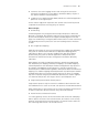
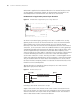
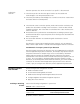
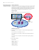
The company accesses the Internet through the Firewall module. It provides WWW
and SMTP services externally. The internal WWW server address is 20.0.0.1; the
internal SMTP server address is 20.0.0.2. Only the external specific PCs can access
the internal server. However, they cannot access other resources of the internal
network. Suppose the IP address of the external specific PC is 210.1.5.1.
Network diagram
Figure 18 Network diagram for packet filtering firewall configuration
Configuration procedure
1 For the internal PC, the IP address is 15.0.0.1/24 and the gateway address is
15.0.0.254.
For the external PC, the IP address is 210.1.5.1.
For the WWW server, the IP address is 20.0.0.1/24 and the gateway address is
20.0.0.254.
For the SMTP server, the IP address is 20.0.0.2/24 and the gateway address is
20.0.0.254.
2 Switch 8807 (SecBlade)
# Divide VLANs.
<SW8800> system-view
[SW8800] vlan 15
[3Com-vlan15] quit
[SW8800] vlan 20
[3Com-vlan20] quit
[SW8800] vlan 30
[3Com-vlan30] quit
SecBlade S 8505
Vlan
3
0
Vlan15
Vlan 50
Vlan
5
0
Interne
t
ݙ䚼 PC 15.0.0.1/ 24
30.0.0. 254/2
4
50.0.0. 254/
4
30.0.0.1/2
4
15.0.0. 254/2
4
Vlan20
WWW
20.0.0.1/24
SMT
20.0.0.2/24
20.0.0. 254/
4
Intrane
t
50.0.0.1/24
External PC
210.1.5.1
SecBlade S 8800
Vlan
30
Vlan15
Vlan 50
Vlan 50
Internet
Internal PC
15.0.0.1/24
30.0.0. 254/24
50.0.0. 254/24
30.0.0.1/2
4
15.0.0. 254/24
Vlan20
WWW
20.0.0.1/24
SMTP
20.0.0.2/24
20.0.0. 254/
24
Intranet
50.0.0.1/24