3Com® Switch 8800 Family IPsec Configuration and Command Reference Guide Switch 8807 Switch 8810 Switch 8814 www.3Com.com Part No. 10015597, Rev.
3Com Corporation 350 Campus Drive Marlborough, MA USA 01752-3064 Copyright © 2006-2007, 3Com Corporation. All rights reserved. No part of this documentation may be reproduced in any form or by any means or used to make any derivative work (such as translation, transformation, or adaptation) without written permission from 3Com Corporation.
CONTENTS ABOUT THIS GUIDE Conventions 7 Related Documentation 8 1 SWITCH 8800 IPSEC MODULE 2 IPSEC MODULE CONFIGURATION IPsec Module Configuration 13 Displaying Information about the IPsec module 3 15 NETWORK SECURITY CONFIGURATION Introduction to the Network Security Features Provided by Comware Hierarchical Command Line Protection 18 RADIUS-Based AAA 18 Packet Filter and Firewall 18 Security Authentication before Route Information Exchange 21 4 17 AAA AND RADIUS/HWTACACS PROTOCOL CONFIGURATION
NAT Configuration 86 Displaying and Debugging NAT 91 NAT Configuration Example 91 Troubleshooting NAT Configuration 94 7 VPN OVERVIEW VPN Overview 97 Fundamental Technology of VPN Classification of VPN 101 8 98 CONFIGURATION OF L2TP Introduction to L2TP Protocol 103 LAC Configuration 108 LNS Configuration 115 Displaying and Debugging L2TP 122 L2TP Configuration Example 123 L2TP Troubleshooting 127 9 CONFIGURATION OF GRE Brief Introduction to GRE 129 GRE Configuration 132 Displaying and Debugging GRE
PKI Configuration Example 200 Troubleshooting Certificates 203 13 DVPN Introduction to DVPN 205 DVPN Configuration 211 DVPN Configuration Example 14 RELIABILITY OVERVIEW Introduction to Reliability 15 222 229 VRRP CONFIGURATIONS Introduction to VRRP 231 Configuring VRRP 232 Displaying and Debugging VRRP 237 VRRP Configuration Examples 237 VRRP Troubleshooting 247 16 IPSEC MODULE CONFIGURATION COMMANDS IPsecModule Configuration Commands 17 249 AAA/RADIUS/HWTACACS CONFIGURATION COMMANDS AAA Confi
23 IKE CONFIGURATION COMMANDS IKE Configuration Commands 24 407 PKI CONFIGURATION COMMANDS PKI Domain Configuration Commands 425 PKI Entity Configuration Commands 432 PKI Certificate Operation Commands 436 PKI Displaying and Debugging Commands 440 25 DVPN CONFIGURATION COMMANDS 26 VRRP CONFIGURATION COMMANDS VRRP Configuration Commands 473
Conventions 7 ABOUT THIS GUIDE This guide describes the 3Com® Switch 8800 and how to install hardware, configure and boot software, and maintain software and hardware. This guide also provides troubleshooting and support information for your switch. This guide is intended for Qualified Service personnel who are responsible for configuring, using, and managing the switches.
ABOUT THIS GUIDE Table 2 Text Conventions Convention Description Words in italics Italics are used to: Emphasize a point. Denote a new term at the place where it is defined in the text. Identify menu names, menu commands, and software button names. Examples: From the Help menu, select Contents. Click OK. Words in bold Related Documentation Boldface type is used to highlight command names. For example, “Use the display user-interface command to...
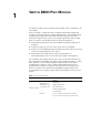
1 SWITCH 8800 IPSEC MODULE This chapter describes the IPsec Module (3CR1754766), which is available for the Switch 8800 The IPsec Module is a high performance encryption VPN module designed for enterprises requiring support for multiple VPN applications, and hardware-based encryption processing. It provides hardware based encrypting of data with a maximum encryption rate of 512-bit. The module supports DES, 3DES and AES types of encryption.
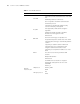
CHAPTER 1: SWITCH 8800 IPSEC MODULE Table 1 IPsec Module Function Attribute Description L2TP VPN Initiating connection to the specified LNS according to the full user name and domain name of the VPN user Distributing addresses for VPN users LCP re-negotiation and CHAP re-authentication AH and ESP protocols Supporting to automatically establish security association manually or through IKE IPsec/IKE ESP supports DES, 3DES and AES encryption algorithms Authentication MD5 and SHA-1 algorithms IKE main
Table 1 IPsec Module Function Attribute Description ARP Static domain name resolution IP service Borrowing IP addresses DHCP relay DHCP server DHCP client Network protocol Static route management RIP-1/RIP-2 IP route OSPF BGP Rout policy Policy route Network reliability Supporting virtual router redundancy protocol to implement device backup Local configuration through the Console interface Remote configuration through the AUX interface Local or remote configuration through Telnet or SSH Configur
CHAPTER 1: SWITCH 8800 IPSEC MODULE
IPSEC MODULE CONFIGURATION 2 IPsec Module Configuration To make the Switch 8800 Family routing switch and IPsec module work together, you need to configure the IPsec module on the switch by: Configuring the Interface Aggregation ■ “Configuring the Interface Aggregation” ■ “Creating the IPsec Module” ■ “Specifying the Layer 3 Interface Connecting the Switch and IPsec module” ■ “Specifying the VLAN Protected by the IPsec module” ■ “Mapping the IPsec module to a slot” ■ “Logging into the IPsec m
CHAPTER 2: IPSEC MODULE CONFIGURATION By default, the IPsec module is not created. Specifying the Layer 3 Interface Connecting the Switch and IPsec module To make the IPsec module and Switch 8800 Family switch communicate at Layer 3, you must specify the Layer 3 interface connecting the switch and the IPsec module. Perform the following configuration in IPsec module view of the switch.
Displaying Information about the IPsec module 15 Table 7 Log into the IPsec module Configuring Default Login User Function Operation Command Log into the IPsec module secblade slot slot-number For login convenience, a user whose name and password are both secblade is created in the IPsec module. You can use this user name and password to log into the IPsec module. Perform the following configuration in IPsec module system view.
CHAPTER 2: IPSEC MODULE CONFIGURATION
NETWORK SECURITY CONFIGURATION 3 n Introduction to the Network Security Features Provided by Comware The content below applies to the IPsec module, so the command views in this document apply to the module and not the Switch 8800 Family switches. A security gateway must be able to withstand the various malicious attacks from the public network. On the other hand, the accidental but destructive access of the user may also result in significant performance decrease and even the operation failure.
CHAPTER 3: NETWORK SECURITY CONFIGURATION The following chapters describe how to configure AAA and RADIUS, user password, firewall and packet filtering. Refer to the VPN part of this manual for IPsec/IKE configuration; refer to “NAT Configuration” for address translation configuration. Hierarchical Command Line Protection The system command lines are protected in a hierarchical way. In this approach, the command lines are divided into four levels: visit, monitor, system, and manage.
Packet Filter and Firewall 19 Figure 1 A firewall separating the intranet from the Internet Internet Firewall Ethernet PC PC 6HUYHU PC The firewall is not only applied to the Internet connection, but also used to protect the mainframe and crucial resources like data on the intranet of the organization. Access to the protected data should be permitted by the firewall, even if the access is initiated from the organization.
CHAPTER 3: NETWORK SECURITY CONFIGURATION ■ Packet filter: Such a firewall filters each packet depending on the items that defined by the user. For example, it compares the packets with the defined rules in source and destination addresses for a match. A packet filter neither considers the status of sessions, nor analyzes the data.
Security Authentication before Route Information Exchange 21 Figure 2 Packet filtering elements Most packet filter systems do not make any operations on data itself or make contents-based filtering. ACL Before the system can filter the packets, you should configure some rules in ACLs to specify the types of packets allowed or denied. A user should configure an ACL according to the security policy and apply it to a particular interface or the whole equipment.
CHAPTER 3: NETWORK SECURITY CONFIGURATION
4 AAA AND RADIUS/HWTACACS PROTOCOL CONFIGURATION Overview Introduction to AAA Authentication, Authorization and Accounting (AAA) provide a uniform framework used for configuring these three security functions to implement the network security management.
CHAPTER 4: AAA AND RADIUS/HWTACACS PROTOCOL CONFIGURATION Accounting AAA supports the following accounting methods: n ■ None accounting: no accounting required. ■ Remote accounting: conducted through a RADIUS server or TACACS server. Currently, security gateway supports accounting of PPP users and Telnet users only, but it does not support real-time accounting of Telnet users. AAA usually utilizes a Client/Server model, where the client controls user access and the server stores user information.
Overview 25 Figure 3 Components of RADIUS server RADIUS Server Users Dictionary Clients In addition, RADIUS servers can act as the client of some other AAA server to provide the proxy authentication or accounting service. They support multiple user authentication methods, such as PPP-based PAP, CHAP and UNIX-based login. Basic message exchange procedures in RADIUS In most cases, user authentication using a RADIUS server always involves a device that can provide the proxy function, such as the NAS.
CHAPTER 4: AAA AND RADIUS/HWTACACS PROTOCOL CONFIGURATION response (Access-Accept) containing the information of user’s right. If the authentication fails, it returns an Access-Reject message. 4 The RADIUS client acts on the returned authentication result to accept or deny the user. If it is allowed to accept the user, the RADIUS client sends an accounting start request (Accounting-Request) to the RADIUS server, with the value of Status-Type being "start".
Overview 27 Table 10 Code values Code Packet type Description 3 Access-Reject The packet is transmitted by the server to the client. If any attribute value carried in the Access-Request is unacceptable, the server rejects the user and sends back an Access-Reject response. Accounting-Request The packet carries user information and is transmitted by the client to the server to request the server to start accounting.
CHAPTER 4: AAA AND RADIUS/HWTACACS PROTOCOL CONFIGURATION The RADIUS protocol is extensible. The Attribute 26 (Vender-Specific) defined in it allows a user to define an extended attribute.
Overview 29 Figure 7 Network diagram for a typical HWTACACS application Terminal user TACACS server 129.7.66.66 ISDN\PSTN Dialup user Switch 8800 TACACS server 129.7.66.67 Basic message exchange procedures in HWTACACS For example, use HWTACACS to implement authentication, authorization, and accounting for a telnet user.
CHAPTER 4: AAA AND RADIUS/HWTACACS PROTOCOL CONFIGURATION Figure 8 The AAA implementation procedures for a telnet user User HWTACACS HWTACACS Client Server User logs in Authentication Start Request packet Authentication response packet , requesting for the user name Request User for the user name User enters the user name Authentication continuance packet carrying the user name Authentication response packet , requesting for the password Request User for the password User enters the password
Configuring AAA Creating an ISP Domain and Setting the Related Attributes 31 Creating an ISP domain An Internet service provider (ISP) domain is a group of users that belong to the same ISP. For a username in the userid@isp-name format, gw20010608@3com163.net for example, the isp-name (3com163.net) following the @ sign is the ISP domain name.
CHAPTER 4: AAA AND RADIUS/HWTACACS PROTOCOL CONFIGURATION Perform the following configuration in ISP domain view. Table 14 Configure the related attributes of the ISP domain Operation Command Configure an AAA scheme for the domain. scheme { radius-scheme radius-scheme-name [ local ] | hwtacacs-scheme hwtacacs-scheme-name [ local ] | local | none } Restore the default AAA scheme. undo scheme [ radius-scheme | hwtacacs-scheme | none ] The default AAA scheme is local.
Configuring AAA 33 You can custom an AAA scheme combination according to the above implementations. ■ For DVPN services At present, only RADIUS, local and RADIUS-local support authentication and authorization, and only RADIUS supports accounting. Perform the following configuration in ISP domain view. Table 15 Configure the related ISP domain attributes Operation Command Configure an authentication scheme for the domain.
CHAPTER 4: AAA AND RADIUS/HWTACACS PROTOCOL CONFIGURATION Table 16 Configure the ISP domain state Operation Command Configure the ISP domain state. state { active | block } By default, an ISP domain is active when it is created. Setting an access limit You can specify the maximum number of users that an ISP domain can accommodate by setting an access limit. Perform the following configuration in ISP domain view.
Configuring AAA 35 ■ Define an address pool in system view and assign it (only one is allowed) to the interface in the view of this interface for assigning addresses to the connected ends. ■ Define address pools in domain view and directly allocate the addresses from the pools to the login domain PPP users. Perform the following configuration in ISP domain view. Table 19 Define an IP address pool for PPP domain users Operation Command Define an IP address pool for allocating addresses to PPP users.
CHAPTER 4: AAA AND RADIUS/HWTACACS PROTOCOL CONFIGURATION Creating a local user A local user is a group of users set on NAS (a security gateway). The username is the unique identifier of a user. A user requesting network service can pass local authentication as long as its information has been added to the local user database of NAS. Perform the following configuration in system view Table 20 Create/delete a local user and the relevant properties Operation Command Add a local user.
Configuring the RADIUS Protocol 37 Table 22 Set/remove the attributes concerned with a specified user Operation Command Authorized DVPN service to the user service-type dvpn Remove the DVPN service authorization undo service-type dvpn Set the directory that can be accessed if the user is an FTP user. service-type ftp [ ftp-directory directory] Restore the default directory that can be accessed if the user is an FTP user.
CHAPTER 4: AAA AND RADIUS/HWTACACS PROTOCOL CONFIGURATION ■ Configure the source address in the RADIUS packets sent by NAS ■ Set timers regarding RADIUS server ■ Configure the RADIUS server to send a trap packet Among these tasks, creating a RADIUS scheme and configuring RADIUS authentication/authorization servers are required, while other tasks are optional at your discretion. Creating a RADIUS Scheme As mentioned earlier, the RADIUS protocol is configured scheme by scheme.
Configuring the RADIUS Protocol 39 Table 24 Configure IP address and port number of RADIUS authentication/authorization servers Operation Command Restore IP address and port number of the primary RADIUS authentication/authorization server to the default values. undo primary authentication Configure IP address and port number of the secondary RADIUS authentication/authorization server.
CHAPTER 4: AAA AND RADIUS/HWTACACS PROTOCOL CONFIGURATION authentication/authorization port and accounting port). When doing this, make sure that the port settings on the security gateway and the RADIUS server are consistent. You can use the display radius command to view the IP addresses and port number of the primary and secondary accounting servers in the RADIUS scheme.
Configuring the RADIUS Protocol 41 Configuring the maximum number of real-time accounting request attempts A RADIUS server usually determines the online state of a user using the connection timeout timer. If the RADIUS sever receives no real-time accounting packets from the NAS for a long time, it considers that the line or device fails and stops user accounting.
CHAPTER 4: AAA AND RADIUS/HWTACACS PROTOCOL CONFIGURATION of transmission attempts exceeds the specified retry-times, the NAS considers the communication with the current RADIUS server has been disconnected and turns to another RADIUS server. You can use the following command to set the maximum number of allowed RADIUS request attempts. Perform the following configurations in RADIUS view.
Configuring the RADIUS Protocol 43 Table 32 Set RADIUS server state Operation Command Set the state of the primary RADIUS authentication/authorization server. state primary authentication { block | active } Set the state of the primary RADIUS accounting server. state primary accounting { block | active } Set the state of the secondary RADIUS authentication/authorization server. state secondary authentication { block | active } Set the state of the secondary RADIUS accounting server.
CHAPTER 4: AAA AND RADIUS/HWTACACS PROTOCOL CONFIGURATION Configuring Source Address for RADIUS Packets Sent by NAS Perform the following configuration in the specified views. Table 35 Configure source address for the RADIUS packets sent by the NAS Operation Command Configure the source address to be carried in the RADIUS packets sent by the NAS(RADIUS view). nas-ip ip-address Cancel the configured source address to be carried in the RADIUS packets sent by the NAS(RADIUS view).
Configuring the RADIUS Protocol 45 information of online users to the RADIUS accounting server at intervals of this value. Perform the following configuration in RADIUS view. Table 38 Set a real-time accounting interval Operation Command Set a real-time accounting interval. timer realtime-accounting minutes Restore the default real-time accounting interval. undo timer realtime-accounting In the command, minutes represents the interval for realtime accounting and it must be a multiple of three.
CHAPTER 4: AAA AND RADIUS/HWTACACS PROTOCOL CONFIGURATION By default, a local RADIUS authentication server with the NAS-IP as 127.0.0.1 and key as 3com is created. n When the local RADIUS authentication server function is enabled, the UDP port number for the authentication/authorization services must be 1645 and that for the accounting service must be 1646.
Configuring HWTACACS Protocol 47 Table 42 Create a HWTACACS scheme Operation Command Delete a HWTACACS scheme. undo hwtacacs scheme hwtacacs-scheme-name If the HWTACACS scheme you specify does not exist, the system creates it and enters HWTACACS view. In HWTACACS view, you can configure the HWTACACS scheme. The system supports up to 128 HWTACACS schemes. You can only delete the schemes that are not being used. By default, no HWTACACS scheme exists.
CHAPTER 4: AAA AND RADIUS/HWTACACS PROTOCOL CONFIGURATION n If TACACS authentication is configured for a user without TACACS authorization server, the user cannot log in regardless of its user type. The primary and secondary authorization servers cannot use the same IP address. Otherwise, the system will prompt unsuccessful configuration. The default port number is 49. If you execute this command repeatedly, the new settings will replace the old settings.
Configuring HWTACACS Protocol Configuring Source Address for HWTACACS Packets Sent by NAS 49 Perform the following configuration. Table 47 Configure the source address to be carried in HWTACACS packets sent by the NAS Operation Command Configure the source address to be carried in HWTACACS packets sent by the NAS(HWTACACS view). nas-ip ip-address Delete the configured source address to be carried in the HWTACACS packets sent by the NAS (HWTACACS view).
CHAPTER 4: AAA AND RADIUS/HWTACACS PROTOCOL CONFIGURATION Table 50 Set the unit of data flows destined for the TACACS server Operation Set the unit of data flows destined for the TACACS server. Restore the default unit of data flows destined for the TACACS server. Command data-flow-format data { byte | giga-byte | kilo-byte | mega-byte } data-flow-format packet { giga-packet | kilo-packet | mega-packet | one-packet } undo data-flow-format { data | packet } By default, data is sent in bytes.
Displaying and Debugging AAA and RADIUS/HWTACACS Protocols 51 Table 53 Set a real-time accounting interval Operation Command Restore the default real-time accounting interval. undo timer realtime-accounting The interval is in minutes and must be a multiple of 3. The setting of real-time accounting interval somewhat depends on the performance of the NAS and the TACACS server: a shorter interval requires higher device performance.
CHAPTER 4: AAA AND RADIUS/HWTACACS PROTOCOL CONFIGURATION Table 56 Display and debug the RADIUS protocol Operation Command Display the statistics on the local RADIUS authentication server. display local-server statistics Enable RADIUS packet debugging. debugging radius packet Disable RADIUS packet debugging. undo debugging radius packet Enable local RADIUS authentication server debugging.
AAA and RADIUS/HWTACACS Protocol Configuration Example 53 Connect the IPsec module to the RADIUS server (functions as both authentication and accounting servers) whose IP address is 10.0.0.1/24. On the IPsec module, set the shared keys both for packet exchange with the authentication server and with the accounting server as "expert". You can use a 3Com CAMS server as the RADIUS server.
CHAPTER 4: AAA AND RADIUS/HWTACACS PROTOCOL CONFIGURATION [3Com-vlan30] quit [SW8800] vlan 50 [3Com-vlan50] quit # Configure the IP address. [SW8800] interface vlan-interface 10 [3Com-Vlan-interface10] ip address 10.0.0.254 24 [3Com-Vlan-interface10] quit [SW8800] interface vlan-interface 30 [3Com-Vlan-interface30] ip address 30.0.0.1 24 [3Com-Vlan-interface30] quit # Configure the static route. [SW8800] ip route-static 0.0.0.0 0 30.0.0.
AAA and RADIUS/HWTACACS Protocol Configuration Example 55 [secblade] firewall zone trust [secblade-zone-trust] add interface GigabitEthernet 0/0.1 [secblade-zone-trust] quit # Add the sub-interface of the external network to the untrust zone. [secblade] firewall zone untrust [secblade-zone-untrust] add interface GigabitEthernet 0/0.2 [secblade-zone-untrust] quit # Configure the static route. [secblade] ip route-static 10.0.0.0 24 30.0.0.1 # Configure the Telnet user to use AAA authentication mode.
CHAPTER 4: AAA AND RADIUS/HWTACACS PROTOCOL CONFIGURATION Configuring FTP/Telnet User Local Authentication n Configuring local authentication for FTP users is similar to that for Telnet users. The following example is based on Telnet users. Network requirements Configure the IPsec module to authenticate the login Telnet users at the local (see the following figure).
AAA and RADIUS/HWTACACS Protocol Configuration Example 57 [SW8800] interface vlan-interface 10 [3Com-Vlan-interface10] ip address 10.0.0.254 24 [3Com-Vlan-interface10] quit [SW8800] interface vlan-interface 30 [3Com-Vlan-interface30] ip address 30.0.0.1 24 [3Com-Vlan-interface30] quit # Configure the static route. [SW8800] ip route-static 0.0.0.0 0 30.0.0.254 # Configure aggregation of IPsec module interfaces (the module resides in slot 2).
CHAPTER 4: AAA AND RADIUS/HWTACACS PROTOCOL CONFIGURATION [secblade] firewall zone untrust [secblade-zone-untrust] add interface GigabitEthernet 0/0.2 [secblade-zone-untrust] quit # Configure the static route. [secblade] ip route-static 0.0.0.0 0 50.0.0.1 [secblade] ip route-static 10.0.0.0 24 30.0.0.1 # Configure the Telnet user to use AAA authentication. [secblade] user-interface vty 0 4 [secblade-ui-vty0-4] authentication-mode scheme # Create the local user telnet.
AAA and RADIUS/HWTACACS Protocol Configuration Example Network diagram Figure 11 Network diagram for remote RADIUS authentication on the Telnet user IPsec Switch 8800 Configuration procedure 1 TACACS Server IP address: 10.0.0.1/24. Gateway: 10.0.0.254. 2 Telnet User IP address: 50.0.0.1/24. 3 Switch 8800 (SecBlade) # Divide VLANs. system-view [SW8800] vlan 10 [3Com-vlan10] quit [SW8800] vlan 30 [3Com-vlan30] quit [SW8800] vlan 50 [3Com-vlan50] quit # Configure the IP address.
CHAPTER 4: AAA AND RADIUS/HWTACACS PROTOCOL CONFIGURATION [SW8800] ip route-static 0.0.0.0 0 30.0.0.254 # Configure aggregation IPsec module interfaces (the IPsec module resides in slot 2). [SW8800] secblade aggregation slot 2 # Create the secblade test. [SW8800] secblade test # Specify the SecBlade interface VLAN. [3Com-secblade-test] secblade-interface vlan-interface 30 # Set the protected VLAN.
AAA and RADIUS/HWTACACS Protocol Configuration Example # Configure the Telnet user to use AAA authentication. [secblade] user-interface vty 0 4 [secblade-ui-vty0-4] authentication-mode scheme # Configure the domain. [secblade] domain cams [secblade-isp-cams] access-limit enable 10 [secblade-isp-cams] accounting optional [secblade-isp-cams] quit # Configure the RADIUS scheme.
CHAPTER 4: AAA AND RADIUS/HWTACACS PROTOCOL CONFIGURATION Step 2: Choose to use the winkey.exe calculator to get the login password at the prompt "s/key 89 gf55236". Figure 13 Calculate login password In the above figure: Type the prompt "89 gf55236" in the Challenge field. Type the private password (test for example) in the Password field. The Response field outputs the calculation result, that is, the password you need to type in the login interface.
Troubleshooting AAA and RADIUS/HWTACACS Protocols 63 Check that: 1 The communication links (at both physical and link layers) between the NAS and the RADIUS server work well. 2 The IP address of the RADIUS server is correctly configured on the NAS. 3 Authentication/Authorization and accounting UDP ports are set in consistency with the port numbers set on the RADIUS server.
CHAPTER 4: AAA AND RADIUS/HWTACACS PROTOCOL CONFIGURATION
ACL CONFIGURATION 5 Introduction to ACL ACL Overview Classification of ACL In order to filter data packets, a series of rules need to be configured on the security gateway to decide which data packets can pass. These rules are defined by ACL (Access Control List), which are a series of sequential rules consisting of the permit and the deny statements. The rules are described by source address, destination address and port number of data packets.
CHAPTER 5: ACL CONFIGURATION and arrange others according to configuration sequence. For advance access control rules, compare their source address wildcards first. If they are the same, compare their destination address wildcards. If they are also the same, compare their ranges of port number. Put those with smaller ranges before others. If the ranges of port number are still the same, arrange then according to configuration sequence.
Introduction to ACL 67 the above-mentioned ACL command. In basic ACL view, the rule of basic ACL can be created. The following command can be used to define a basic ACL rule: rule [ rule-id ] { permit | deny } { source sour-addr sour-wildcard | any } ] [ time-range time-name ] [ logging ] [ fragment ] Parameter description: ■ rule-id: Optional, number of ACL rule, ranging from 0 to 65,534.
CHAPTER 5: ACL CONFIGURATION The following command can be used to delete a basic ACL rule: undo rule rule-id [ source ] [ time-range ] [ logging ] [ fragment ] Parameter description: Advanced ACL ■ rule-id: Number of ACL rule, which should be an existing ACL rule number. If there is no parameter followed, the entire ACL rule will be deleted. Otherwise, only part of information related to the ACL rule will be deleted. ■ source: Optional parameter.
Introduction to ACL 69 ■ protocol: IP carried protocol type represented by name or number. The number range is from 1 to 255. The name can be gre, icmp, igmp, ip, ipinip, ospf, tcp, and udp. ■ source: Optional parameter, used to specify source address information of ACL rule. If it is not configured, it indicates any source address of the packet matches. ■ source-addr: Source address of data packet, in dotted decimal.
CHAPTER 5: ACL CONFIGURATION ■ tos tos: Optional parameter. Data packet can be filtered according to service type field. A number ranging from 0 to 15 or a name. This keyword is mutually exclusive with the dscp keyword. ■ logging: Optional parameter, indicating whether to log qualified data packet.
Introduction to ACL 71 ■ rule-id: Number of ACL rule, which should be an existing ACL rule number. If there is no parameter followed, the entire ACL rule will be deleted. Otherwise, only part of information related to the ACL rule will be deleted. ■ source: Optional parameter. Only the source address information setting of ACL rule with corresponding number will be deleted. ■ destination: Optional parameter.
CHAPTER 5: ACL CONFIGURATION Table 59 Port number mnemonics Protocol TCP Mnemonics Meaning and actual value Bgp Border Gateway Protocol (179) Chargen Character generator (19) Cmd Remote commands (rcmd, 514) Daytime Daytime (13) Discard Discard (9) Domain Domain Name Service (53) Echo Echo (7) Exec Exec (rsh, 512) Finger Finger (79) Ftp File Transfer Protocol (21) Ftp-data FTP data connections (20) Gopher Gopher (70) Hostname NIC hostname server (101) Irc Internet Relay Ch
Introduction to ACL 73 Table 59 Port number mnemonics Protocol Mnemonics Meaning and actual value UDP biff Mail notify (512) bootpc Bootstrap Protocol Client (68) bootps Bootstrap Protocol Server (67) discard Discard (9) dns Domain Name Service (53) dnsix DNSIX Security Attribute Token Map (90) echo Echo (7) mobilip-ag MobileIP-Agent (434) mobilip-mn MobilIP-MN (435) nameserver Host Name Server (42) netbios-dgm NETBIOS Datagram Service (138) netbios-ns NETBIOS Name Service (137)
CHAPTER 5: ACL CONFIGURATION Table 60 Mnemonics of ICMP packet type Mnemonic Meaning echo Type=8, Code=0 echo-reply Type=0, Code=0 fragmentneed-DFset Type=3, Code=4 host-redirect Type=5, Code=1 host-tos-redirect Type=5, Code=3 host-unreachable Type=3, Code=1 information-reply Type=16,Code=0 information-request Type=15,Code=0 net-redirect Type=5, Code=0 net-tos-redirect Type=5, Code=2 net-unreachable Type=3, Code=0 parameter-problem Type=12,Code=0 port-unreachable Type=3, Code
Introduction to ACL 75 specified number to create a new rule. When the number is not specified, it means to add a new rule. In this case, the system will assign a number automatically for the ACL rule and add the new rule. ■ deny: Discards qualified data packet. ■ permit: Permits qualified data packet. ■ interface interface-type interface-number: Specifies the interface information of the packets. If no interface is specified, all interfaces can be matched. any represents all interfaces.
CHAPTER 5: ACL CONFIGURATION sour-addr represents the source MAC address of a data frame in the format of xxxx-xxxx-xxxx. sour-mask represents the wildcard of the source MAC address. dest-addr represents the destination MAC address in the format of xxxx-xxxx-xxxx. dest-mask represents the wildcard of the destination MAC address.
Configuring an ACL Configuring a Basic ACL ■ Add description to an ACL ■ Add comment to an ACL rule ■ Delete an ACL 77 Perform the following configuration. Table 61 Configure a basic ACL Operation Command Create a basic ACL in system view. acl number acl-number [ match-order { config | auto } ] Configure/delete an ACL rule in basic ACL view.
CHAPTER 5: ACL CONFIGURATION Table 64 Configure a MAC-based ACL Operation Command Create a MAC-based ACL in system view. acl number acl-number Configure/delete an ACL rule in MAC-based ACL view. rule [ rule-id ] { deny | permit } [ type type-code type-mask | lsap lsap-code lsap-mask ] [ source-mac sour-addr sour-wildcard ] [ dest-mac dest-addr dest-mask ] [ time-range time-name ] undo rule rule-id Adding Description to an ACL You can add description to an ACL for reminding purpose.
Displaying and Debugging ACL 79 Table 68 Configure time range Displaying and Debugging ACL Operation Command Create a time range time-range time-name [ start-time to end-time ] [ days ] [ from time1 date1 ] [ to time2 date2 ] Delete a time range.
CHAPTER 5: ACL CONFIGURATION
NAT CONFIGURATION 6 NAT Overview Introduction to NAT n As described in RFC1631, Network Address Translation (NAT) is to translate the IP address in IP data packet header into another IP address, which is mainly used to implement private network accessing external network in practice. NAT can reduce the depletion speed of IP address space via using several public IP addresses to represent multiple private IP addresses.
CHAPTER 6: NAT CONFIGURATION destination address in the header is an extranet address, the server will translate the source address 192.168.1.3 into a valid public address on the Internet 202.169.10.1, then forward the packet to the external server and record the mapping in the network address translation list. The external server sends the response packet2 (The destination is 202.169.10.1) to the NAT server.
Functions Provided by NAT 83 Security gateway implements many-to-many address translation and address translation control via address pool and ACL respectively. NAPT ■ Address pool: A set of public IP addresses for address translation. A client should configure an appropriate address pool according to its valid IP address number, internal host number as well as the actual condition. An address will be selected from the pool as the source address during the translation process.
CHAPTER 6: NAT CONFIGURATION converted and the host part is unchanged). When internal hosts access the outside network, their internal addresses are converted to public network addresses if their internal addresses are in the specified range. Accordingly, outside hosts can use the public network address to access directly internal hosts if the internal host addresses which are converted from the public network addresses are in the specified range.
Functions Provided by NAT 85 Temporary address = Start address of the temporary address pool + (overlap address - start address of the overlap address pool) Overlap address = Start address of the overlap address pool + (temporary address start address of the temporary address pool) When PC2 accesses PC3 with the domain name, packets are processed as follows: 1 PC2 sends a DNS request for resolving www.web.
CHAPTER 6: NAT CONFIGURATION NAT application level gateway (ALG), a common solution to special protocol traversal, replaces the IP addresses and port numbers in payload based on NAT rules, and achieves transparent protocol relay. Currently, NAT ALG supports PPTP, DNS, FTP, ILS, NBT, H.323 and other protocols. NAT Configuration NAT configuration includes: Configuring Address Pool ■ Configure address pool.
NAT Configuration 87 translated address and the ACL can be used to control which addresses can be translated. Perform the following configuration under the interface view. Table 71 Configure Easy IP Operation Command Add association for access control list and address pool nat outbound acl-number Delete association for access control list and address pool undo nat outbound acl-number Associating ACL with Loopback interface address Perform the following configuration in interface view.
CHAPTER 6: NAT CONFIGURATION The nat static inside ip and nat static commands create two different types of static NAT entries. Note that the two types cannot be in conflict. c CAUTION: When configuring static inside ip NAT, you must make sure that the addresses after translation are not used by other devices in the network topology. 3 Applying static NAT entries on the interface Perform the following configuration in interface view.
NAT Configuration 89 Table 78 Configure bidirectional NAT table Configuring Internal Server Operation Command Configure the mapping from the overlap address pool to the temporary address pool nat overlapaddress number overlappool-startaddress temppool-startaddress { pool-length pool-length | address-mask mask } Remove the mapping from the overlap address pool to the temporary address pool undo nat overlapaddress number By configuring internal server, the related external address and port can be ma
CHAPTER 6: NAT CONFIGURATION Configuring Domain Name Mapping If the internal network does not have the DNS server, but does have several different internal servers (such as FTP and WWW). Internal hosts want to use different domain names to differentiate the servers and access them. You can use this command to match the requirements. Perform the following configuration in system view.
Displaying and Debugging NAT Displaying and Debugging NAT 91 After the above configuration, execute the display command in all views to display the running of the NAT configuration, and to verify the effect of the configuration. Execute the reset command in user views to clear the running. Execute the debugging command in user view for the debugging of NAT.
CHAPTER 6: NAT CONFIGURATION Network diagram Figure 18 Network diagram for NAT configuration Switch 8800 Configuration procedure 1 For the PC, the IP address is 10.0.0.1/24 and gateway address is 10.0.0.254. For the WWW Server, the IP address is 10.0.1.1/24 and gateway address is 10.0.1.254. For the FTP Server, the IP address is 10.0.1.2/24 and gateway address is 10.0.1.254. For the SMTP Server, the IP address is 10.0.1.3/24 and gateway address is 10.0.1.254.
NAT Configuration Example 93 [SW8800] interface vlan-interface 10 [3Com-Vlan-interface10] ip address 10.0.0.254 24 [3Com-Vlan-interface10] quit [SW8800] interface vlan-interface 20 [3Com-Vlan-interface20] ip address 10.0.1.254 24 [3Com-Vlan-interface20] quit [SW8800] interface vlan-interface 30 [3Com-Vlan-interface30] ip address 30.0.0.1 24 [3Com-Vlan-interface30] quit # Configure the static route. [SW8800] ip route-static 0.0.0.0 0 30.0.0.
CHAPTER 6: NAT CONFIGURATION [secblade] firewall zone trust [secblade-zone-trust] add interface GigabitEthernet 0/0.1 [secblade-zone-trust] quit # Add the sub-interface of the external network to the untrust zone. [secblade] firewall zone untrust [secblade-zone-untrust] add interface GigabitEthernet 0/0.2 [secblade-zone-untrust] quit # Configure the static route. [secblade] ip route-static 0.0.0.0 0 202.38.160.200 [secblade] ip route-static 10.0.0.0 16 30.0.0.1 # Configure the address pool and ACL.
Troubleshooting NAT Configuration 95 Troubleshooting: if an external host can not access the internal server normally, check the configuration on the internal server host, or the internal server configuration on the security gateway. It is possible that the internal server IP address is wrong, or that the firewall has inhibited the external host to access the internal network. Use the command display acl for further check.
CHAPTER 6: NAT CONFIGURATION
VPN OVERVIEW 7 n VPN Overview The content below applies to the IPsec module, so the command views in this document apply to the module and not the Switch 8800 Family switches. Along with the increasingly wide application of the Internet, Virtual Private Network (VPN) emerged to construct private networks on public networks. "Virtual" here mainly indicates that VPN is a kind of logical networks.
CHAPTER 7: VPN OVERVIEW Structure of VPN Network ■ Add or delete users through software configuration rather than changing hardware facilities, thus delivering great flexibility. ■ Support mobile access of VPN users at any time in any place, thus meeting growing mobile service demands. VPN comprises a group of sites. A site might join one or more VPNs, but any two sites are IP reachable only if they belong to the same VPN.
Fundamental Technology of VPN 99 Figure 20 Diagram for VPN application Remote Subscriber PSTN/ISDN POP PC POP Internet ISP IP Frame Relay ATM POP Corporate Headquarter Cooperator Internal Server It can be seen that enterprise internal resource sharers can access local ISP at its POP (Point of Presence) server via PSTN/ISDN network or local network and access the internal resources of the company.
CHAPTER 7: VPN OVERVIEW Layer 2 Tunneling protocols Layer 2 Tunneling protocols encapsulate PPP frames entirely into internal Tunnels. The existing layer 2 Tunneling protocols include: ■ PPTP (Point to Point Tunneling Protocol): Supported by companies like Microsoft, Ascend, and 3COM and in OS of Windows NT 4.0 and its later versions. This protocol supports Tunneling encapsulation of PPP in IP networks.
Classification of VPN 101 Normally, layer 2 Tunneling protocols and layer 3 Tunneling protocols are used separately. The reasonable combination of two types of protocols, however, may deliver better security and functions (e.g. using L2TP and IPsec together). Classification of VPN IP VPN means emulating private line service of WAN (e.g. remote dial-up, DDN, etc.) over IP networks (including the Internet or dedicated IP backbone).
CHAPTER 7: VPN OVERVIEW Virtual Private Dial Network (VPDN) means implementing virtual private network by employing the dial-up function of public networks (e.g. ISDN and PSTN) and access networks, to provide access service for enterprises,, small ISPs, and mobile businesspersons. 3 VPLS service Virtual Private LAN Segment (VPLS) interconnects LANs via virtual private network segments in virtue of IP public networks. It is an extension of LANs on IP public networks.
8 CONFIGURATION OF L2TP Introduction to L2TP Protocol VPDN Overview Virtual Private Dial Network (VPDN) means implementing virtual private network by employing the dial-up function of public networks (e.g. ISDN and PSDN) and access networks, thus providing access service for enterprises, small ISPs and mobile businessmen. VPDN sets up safe virtual private networks in public networks for enterprises by making use of special network encryption protocols.
CHAPTER 8: CONFIGURATION OF L2TP L2TP provides Tunnel transmission for PPP link layer packets. It extents PPP model in that it permits link endpoint of layer 2 and PPP session point staying at different devices and allows information interaction by using packet switching network technologies. It combines the advantages of PPTP and L2F. Therefore, it becomes the industrial standard of IETF in layer 2 Tunneling.
Introduction to L2TP Protocol 105 L2TP data channel. Control message is transmitted in reliable L2TP control channel. Usually L2TP data is carried in UDP packets for transmission. L2TP registers the UDP port 1701, but this port is only used for the Tunnel setup at the early stage. L2TP Tunnel initiator selects an arbitrary port from available ones (unnecessarily being 1701) and forwards packets to 1701 port of the receiver.
CHAPTER 8: CONFIGURATION OF L2TP Figure 24 Two typical L2TP Tunnel modes LAC client LAC Internet PSTN/ISDN Remote system LAC LNS Internal server LNS Internal server Frame Relay or ATM 1 Initiated by remote dial-up user. Remote system dials in LAC via PSTN/ISDN. LAC sends Tunnel setup request to LNS through the Internet. Dial-up users’ addresses are assigned by LNS.
Introduction to L2TP Protocol 107 Figure 26 Call setup flow of L2TP channel LAC LAC RADIUS Server PC LNS RADIUS Server LNS (1) Call Setup (2) PPP LCP Setup (3) PAP or CHAP authentication (4) access request (5) access accept (6) Tunnel establishment (7) PAP or CHAP authentication (challenge/response) (8) authentication passes (9) user CHAP response, ppp negotiation parameter (10) access request (11) access accept (12) CHAP authentication twice(challenge/response) (13) access request (15) authentica
CHAPTER 8: CONFIGURATION OF L2TP 12 If local mandatory CHAP authentication is configured at LNS, LNS will authenticate the VPN user by sending CHAP challenge and the VPN user at PC sends back responses; 13 LNS resends this access request to RADIUS for authentication; 14 RADIUS server re-authenticates this access request and sends back a response if authentication is successful; 15 The authentication passes and the VPN user can use the internal resources of the enterprise.
LAC Configuration 109 By default, L2TP is disabled. Creating L2TP Group L2TP group needs to be created in order to fulfill related parameter configurations of L2TP. It allows you not only to configure L2TP functions as needed but also to implement one-to-one and one-to-many networking applications between LAC and LNS. L2TP groups are numbered separately on LAC and LNS, so LAC and LNS only need to keep consistent in the configurations of the involved L2TP groups (e.g.
CHAPTER 8: CONFIGURATION OF L2TP does not find the required L2TP group, the system continues to search for the required L2TP group according to the domain name. Setting Tunnel Name A user can configure local Tunnel name on LAC side. The Tunnel name of LAC side must keep in line with the remote name of Tunnel configured on LNS side. These configurations are optional on LAC side. Perform the following configuration inL2TP group view.
LAC Configuration 111 Perform the following configuration in L2TP group view. Table 89 Set transfer mode of AVP data Operation Command Configure to transfer AVP data in the hidden mode tunnel avp-hidden Restore default transfer mode of AVP undo tunnel avp-hidden By default, AVP is transferred in plain text.
CHAPTER 8: CONFIGURATION OF L2TP Table 91 Configure a username and password Operation Command Configure local user password (in local user view) password { simple | cipher } password By default, no local username and password are configured at the LAC side. Configuring PPP user authentication mode Perform the following configuration in virtual template interface view.
LAC Configuration 113 Perform the following configuration in L2TP group view. Table 95 Set flow control function of a Tunnel Operation Command Enable flow control function of a Tunnel tunnel flow-control Disable flow control function of a Tunnel undo tunnel flow-control By default, the flow control function of Tunnels is disabled.
CHAPTER 8: CONFIGURATION OF L2TP Table 98 Start an L2TP Tunnel connection Setting LAC to Function as Client Operation Command Start an L2TP Tunnel connection start l2tp tunnel Normally, the L2TP client is the host that dials to the LAC, where the connection between the user and the LAC is always PPP connection. If the LAC is functioning as the client, the connection between the host and the LAC can be an IP connection allowing the LAC to forward the IP packets from the host to the LNS.
LNS Configuration 115 Table 100 Configure the parameters of the virtual template interface Operation Command Configure the username and password for PAP authentication ppp pap local-user user-name password { simple | cipher } password Enabling/disabling the LAC client to set up L2TP Tunnel Perform the following configuration in virtual template interface view.
CHAPTER 8: CONFIGURATION OF L2TP These configurations are compulsory on LNS side. Perform the following configuration in system view. Table 102 Enable/disable L2TP Operation Command Enable L2TP l2tp enable Disable L2TP undo l2tp enable By default, L2TP is disabled. Enabling/Disabling the L2TP Multi-Domain Function A security gateway can function as LNS for multiple enterprises only when the L2TP multi-domain function is enabled.
LNS Configuration Creating Virtual Template Interface 117 Virtual template interface is mainly used to configure parameters of virtual interface created dynamically by the security gateway in operation, e.g. MP logical interface and L2TP logical interface, etc. These configurations are compulsory on LNS side. Perform the following configuration in system view.
CHAPTER 8: CONFIGURATION OF L2TP These configurations are optional on LNS side. Perform the following configuration in L2TP group view. Table 107 Set local name Operation Command Set local name tunnel name name Restore the default value of local name undo tunnel name By default, local name is the hostname of the security gateway. Setting Tunnel Authentication and Password As needed, a user can decide whether to start Tunnel authentication before creating Tunnel connection.
LNS Configuration 119 Table 109 Set the transfer mode of AVP data Operation Command Restore default transfer mode of AVP undo tunnel avp-hidden By default, AVP is transferred in plain text. Setting Hello Interval in Tunnel In order to check the connectivity of the Tunnel between LAC and LNS, LAC and LNS send Hello packets to each other periodically and the receiver will respond upon the receipt of the packets.
CHAPTER 8: CONFIGURATION OF L2TP Table 111 Enable mandatory local CHAP authentication Operation Command Enable mandatory local CHAP authentication mandatory-chap Disable local CHAP authentication undo mandatory-chap If neither LCP re-negotiation nor mandatory CHAP authentication is configured, LNS will perform agent authentication on the user. In this case, LAC sends LNS all authentication information received from the user as well as authentication mode configured on LAC side.
LNS Configuration 121 mandatory CHAP authentication, the system uses the address pool configured in domain view for address assignment; if LNS adopts mandatory LCP re-negotiation, the system uses the global address pool for address assignment. These configurations are required on LNS side. Perform the following configuration in virtual template interface view. Table 113 Set local address and assigned address pool Operation Command Set local IP address ip address X.X.X.
CHAPTER 8: CONFIGURATION OF L2TP Table 114 Disconnect a connection by force Enabling/Disabling Flow Control Function of Tunnel Operation Command Disconnect a session reset l2tp session session-id Disconnect a user reset l2tp user-name user-name This configuration can enable/disable the simple flow control function on a Tunnel. These configurations are optional on LAC side. Perform the following configuration in L2TP group view.
L2TP Configuration Example 123 Table 117 Display and debug L2TP L2TP Configuration Example Operation Command Disable PPP packet debugging undo debugging l2tp dump Enable L2TP error debugging debugging l2tp error Disable L2TP error debugging undo debugging l2tp error Enable L2TP event debugging debugging l2tp event Disable L2TP event debugging undo debugging l2tp event Enable hidden AVP debugging debugging l2tp hidden Disable hidden AVP debugging undo debugging l2tp hidden Enable L2TP pay
CHAPTER 8: CONFIGURATION OF L2TP Network diagram Figure 27 Network diagram for L2TP Switch 8800 10.0.0.1/24 Configuration procedure 1 PC IP address: 10.0.0.1/24 Gateway: 10.0.0.254 2 NAS # Set a system user. system-view [NAS] local-user vpdnuser [NAS-luser-vpdnuser] password simple Hello [NAS-luser-vpdnuser] service-type ppp [NAS-luser-vpdnuser] quit # Configure a virtual template interface.
L2TP Configuration Example 125 [NAS] interface GigabitEthernet 0/1 [NAS-GigabitEthernet0/1] ip address 50.0.0.1 24 [NAS-GigabitEthernet0/1] quit # Enable L2TP service. [NAS] l2tp enable # Set an L2TP group. [NAS] l2tp-group 1 [NAS-l2tp1] Tunnel authentication [NAS-l2tp1] Tunnel password simple secblade [NAS-l2tp1] Tunnel name LAC [NAS-l2tp1] start l2tp ip 50.0.0.254 fullusername l2tp [NAS-l2tp1] quit # Configure a static route. [NAS] ip route-static 0.0.0.0 0 50.0.0.
CHAPTER 8: CONFIGURATION OF L2TP # Set the VLAN to be protected. [3Com-secblade-test] security-vlan 50 # Map the IPsec module to the IPsec module in the specified slot. [3Com-secblade-test] map to slot 2 [3Com-secblade-test] quit [SW8800] quit # Log into the IPsec module in the specified slot. secblade slot 2 (Both the default user name and password are SecBlade) user: SecBlade password: SecBlade system-view # Create a sub-interface. [secblade] interface GigabitEthernet 0/0.
L2TP Troubleshooting 127 # Enable L2TP service. [secblade] l2tp enable # Set an L2TP group. [secblade-l2tp1] [secblade-l2tp1] [secblade-l2tp1] [secblade-l2tp1] [secblade-l2tp1] Tunnel authentication Tunnel password simple secblade Tunnel name LNS allow l2tp virtual-template 0 remote LAC quit # Configure a static route. [secblade] ip route-static 0.0.0.0 0 50.0.0.1 [secblade] ip route-static 10.0.0.0 24 30.0.0.1 # Quit the IPsec module configuration view.
CHAPTER 8: CONFIGURATION OF L2TP 3 The types of Tunnel password authentication are inconsistent. The default authentication type of VPN connection created by Windows 2000 is MSCHAP. If the peer end does not support MSCHAP, CHAP is recommended for substitution. Symptom 2: Data transmission fails. After the connection is established, no data can be transmitted, e.g. the peer end cannot be pinged.
9 Brief Introduction to GRE CONFIGURATION OF GRE GRE overview Generic Routing Encapsulation protocol (GRE) can encapsulate datagrams of some network layer protocols (e.g. IP and IPX) and allow these encapsulated datagrams to be transferred in another network layer protocol (e.g. IP). GRE is a layer 3 Tunnel protocol of VPN, adopting a technique called Tunnel between protocol layers.
CHAPTER 9: CONFIGURATION OF GRE When receiving a datagram needed encapsulating and routing, called payload, the system first add a GRE header to the datagram to form a GRE packet. This GRE packet is then encapsulated into an IP packet, thus allowing the IP layer to take full charge of the forwarding of the packet. The IP protocol in this particular case is called Delivery Protocol or Transport Protocol.
Brief Introduction to GRE 131 communicate with Group2 and Term1 with Term2 without interfering with each other. 2 Expanding the operating area of networks running hop-limited protocols (e.g. IPX) Figure 32 Expanding network operating area Switch8800A Switch8800B Tunnel IP network IP network Router Router IP network PC r PC r If the hop count between two terminals in the above figure is more than 15, the two terminals cannot communicate with each other.
CHAPTER 9: CONFIGURATION OF GRE multicast data with GRE, and then encrypt the encapsulated data using IPsec. Thus, data secrecy in transmission can be achieved. In addition, GRE also supports users to select and record identification key of Tunnel interface, and supports the end-to-end check of encapsulated message.
GRE Configuration 133 actual physical interface forwarding GRE packets, thus improving the forwarding efficiency. Setting Encapsulation Mode Encapsulation protocol and delivery protocol are to be configured on Tunnel interface. You may choose not to configure them on both ends of the Tunnel, but if you do configure them, make sure to use the same encapsulation mode on both ends (by far, only GRE is available). Perform the following configuration in Tunnel interface view.
CHAPTER 9: CONFIGURATION OF GRE Table 121 Specify destination address of the Tunnel Operation Command Set destination address of the Tunnel destination ip-addr Delete the destination address of the Tunnel undo destination n The destination command sets IP address of actual physical interface. In order to support dynamic routing protocols, network address of Tunnel interface also needs configuring.
GRE Configuration 135 the sender and the receiver. The verification will fail if different identification keys are used, and the packet will be discarded. Perform the following configuration in Tunnel interface view. Table 124 Set identification key of the Tunnel interface Operation Command Set identification key of the Tunnel interface gre key key-number Cancel the identification key of Tunnel interface undo gre key The key-number parameter is an integer in the range 0 to 4294967295.
CHAPTER 9: CONFIGURATION OF GRE Displaying and Debugging GRE Upon the completion of the above configurations, execute the display command in any view to view their running state and to verify the effect of the configurations. The debugging command can be used in user view.
GRE Configuration Example 137 # Configure the interface address. system-view [Router] interface GigabitEthernet 0/0 [Router-GigabitEthernet0/0] ip address 50.0.0.1 24 [Router-GigabitEthernet0/0] quit [Router] interface GigabitEthernet 0/1 [Router-GigabitEthernet0/1] ip address 60.0.0.1 24 [Router-GigabitEthernet0/1] quit 4 3Com_A (SecBlade_A) # Divide VLANs.
CHAPTER 9: CONFIGURATION OF GRE <3Com_A> secblade slot 2 (Both the default user name and password ar e SecBlade) user: SecBlade password: SecBlade system-view # Create the sub-interface. [secblade_A] interface g0/0.1GigabitEthernet 0/0.1 [secblade_A-GigabitEthernet0/0.1] vlan-type dot1q vid 30 [secblade_A-GigabitEthernet0/0.1] ip address 30.0.0.254 24 [secblade_A-GigabitEthernet0/0.1] quit [secblade_A] interface GigabitEthernet 0/0.2 [secblade_A-GigabitEthernet0/0.
GRE Configuration Example 139 # Divide VLANs. <3Com_B> system-view [3Com_B] vlan 20 [3Com_B-vlan20] quit [3Com_B] vlan 40 [3Com_B-vlan40] quit [3Com_B] vlan 60 [3Com_B-vlan60] quit # Configure the IP addresses. [3Com_B] interface vlan-interface 20 [3Com_B-Vlan-interface20] ip address 20.0.0.254 24 [3Com_B-Vlan-interface20] quit [3Com_B] interface vlan-interface 40 [3Com_B-Vlan-interface40] ip address 40.0.0.1 24 [3Com_B-Vlan-interface40] quit # Configure the static route. [3Com_B] ip route-static 0.0.0.
CHAPTER 9: CONFIGURATION OF GRE [secblade_B] interface g0/0.2 [secblade_B-GigabitEthernet0/0.2] vlan-type dot1q vid 60 [secblade_B-GigabitEthernet0/0.2] ip address 60.0.0.1 24 [secblade_B-GigabitEthernet0/0.2] quit # Create the Tunnel interface. [secblade_B] interface Tunnel 0 # Configure the Tunnel IP address. [secblade_B-Tunnel0] ip address 100.0.0.2 24 # Configure Tunnel encapsulation mode. [secblade_B-Tunnel0] tunnel-protocol gre # Configure the source address of the Tunnel.
GRE Troubleshooting 141 Figure 36 Troubleshooting example of GRE Switch88001 PC A 10.1.1.1/16 Ethernet1/0/0 Tunnel1/0/0 Switch88003 Tunnel Switch88002 Ethernet2/0/1 Tunnel2/0/0 PC B 10.2.1.1/16 Symptom 1: The interfaces at both ends of the Tunnel are correctly configured and both ends of the Tunnel can "ping" each other successfully, but PC A and PC B fail to do so.
CHAPTER 9: CONFIGURATION OF GRE
IPSEC CONFIGURATION 10 IPsec Overview IPsec n IP Security (IPsec) protocol family is a series of protocols defined based on IETF. It provides high quality, interoperable and cryptology-based security for IP data packets. The two sides of communication perform encryption and data source authentication on IP layer to assure confidentiality, data integrity, data origin authentication and anti-replay for packets when they are being transmitted on networks.
CHAPTER 10: IPSEC CONFIGURATION Overview of Encryption Card IPsec may use ESP or AH protocol to process packets. For high security purpose, complicated encryption/decryption/authentication algorithms are often used. The IPsec on a security gateway uses many CPU resources for encryption/decryption algorithm, so the overall performance may be degraded. To solve this problem, you can insert an encryption card for a modularized security gateway, on which IPsec operations are processed by hardware.
IPsec Overview 145 Working mode of IPsec protocol IPsec protocol falls into two working modes: transport mode and Tunnel mode. They are specified in SA. In the transport mode, AH/ESP is inserted after the IP header but before all transmission layer protocols or all other IPsec protocols. In the Tunnel mode, AH/ESP is inserted before the original IP header but after the new header.
CHAPTER 10: IPSEC CONFIGURATION decrypting data with identical key via symmetric key system. IPsec in Comware implements three types of encryption algorithms: ■ DES (Data Encryption Standard): Encrypt a 64-bit clear text via a 56-bit key. ■ 3DES (Triple DES): Encrypt a clear text via three 56-bit keys (168 bits key). ■ AES (Advanced Encryption Standard): 128-bit 192-bit and 256-bit AES algorithm, conforming to IETF standards, can be implemented on Comware.
IPsec Overview 147 The following describers how DPD operates after being enabled: ■ At the sender side An IKE peer does not receive IPsec packets from its peer when interval-time timer expires and now, it wants to send IPsec packets to its peer. Before that, the IKE peer sends a DPD query to its peer for proof of liveliness. At the same time, a time_out timer is started. If no acknowledgement is received upon expiration of this timer, DPD records one failure event.
CHAPTER 10: IPSEC CONFIGURATION IPsec proposal prescribes security protocol, authentication algorithm and encryption algorithm as well as operation mode (namely, the packet encapsulation mode) for data flows to be protected. AH and ESP supported by Comware can be used either independently or corporately. AH supports MD5 and SHA-1 authentication algorithms. ESP supports MD5 and SHA-1 authentication algorithms as well as DES and 3DES encryption algorithms.
IPsec Configuration ■ Import ACL into IPsec policy ■ Configure starting and end points for Tunnel ■ Configure SPI for SA ■ Configure SA keys 149 For IKE mode: ■ Create IPsec policy using IKE ■ Import card SA proposal into IPsec policy ■ Import ACL into IPsec policy ■ Import IKE peer into IPsec policy ■ Configure SA duration (optional) ■ Configure PFS feature for negotiation (optional) An IPsec policy can reference an IPsec proposal or card SA proposal as needed.
CHAPTER 10: IPSEC CONFIGURATION Peer end: acl number 3101 rule 1 permit ip source 173.2.2.0 0.0.0.255 destination 173.1.1.0 0.0.0.255 n ■ IPsec protects the data flow permitted in the ACL, therefore, the users are recommended to configure the ACL accurately, that is, configure permit only to the data flow needing IPsec protection so as to avoid the excessive use of the key word any. ■ The users are recommended to configure the ACLs of local and peer ends as the mirror of each other.
IPsec Configuration 151 Table 127 Configure an IPsec proposal Operation Command Create an IPsec proposal and access the IPsec proposal view (for IPsec module) ipsec proposal proposal-name Delete the IPsec proposal (for IPsec module) undo ipsec proposal proposal-name Create a card SA proposal and access its view ipsec card-proposal proposal-name (for encryption cards only ) Delete the card SA proposal (for encryption card) undo ipsec card-proposal proposal-name By default, no IPsec proposal is conf
CHAPTER 10: IPSEC CONFIGURATION Selecting security protocol The security protocol needs specifying in the IPsec proposal and by far AH and ESP are the only two options. You are allowed to use AH, ESP, or both, but the choice must be the same as that at the remote end of the security Tunnel. Perform the following configuration in the IPsec proposal or card SA proposal view.
IPsec Configuration 153 ESP protocol supports three types of encryption algorithms: des, 3des and aes, and two authentication algorithms: hmac-md5 and hmac-sha1. AH protocol supports two types of authentication algorithms: hmac-md5 and hmac-sha1. By default, encryption algorithm used by ESP is des and authentication method used is md5. Authentication method used by AH protocol is md5. n Only when the desired security protocol is selected with the transform command, can security algorithm be configured.
CHAPTER 10: IPSEC CONFIGURATION IPsec policy will specify security protocol algorithm and packet encapsulation format by referencing IPsec proposal. Before an IPsec proposal is referenced, this IPsec proposal must be configured. Perform the following configuration in system view. Table 133 Use IPsec proposal in IPsec policy Operation Command Configure IPsec proposal referenced by IPsec policy proposal proposal-name1 [ proposal-name2...
IPsec Configuration 155 Table 135 Configure Tunnel start/end point Operation Command Delete the peer address configured in the IPsec policy undo tunnel remote [ ip-address ] With respect to an IPsec policy set up manually, only if both local and peer addresses are correctly configured, can a security Tunnel be set up. (As ISAKMP SA can automatically obtain local and peer addresses, it does not require the configuration of local or peer address.
CHAPTER 10: IPSEC CONFIGURATION Table 137 Configure key used by security association Operation Command undo sa string-key { inbound | outbound } { ah | esp } Delete configured security association parameter undo sa authentication-hex { inbound | outbound } { ah | esp } undo encryption-hex { inbound | outbound } esp On both ends of security Tunnel, configured Security Association parameters must be consistent.
IPsec Configuration 157 An IPsec proposal is referenced in an IPsec policy to specify IPsec protocol, algorithms, and packet encapsulation mode. Before an IPsec proposal can be referenced, it must have been created. Perform the following configurations in IPsec policy view. Table 139 Reference an IPsec proposal in the IPsec policy Operation Command Reference an IPsec proposal in the IPsec policy proposal proposal-name1 [ proposal-name2...
CHAPTER 10: IPSEC CONFIGURATION Table 141 Reference an ACL in the IPsec policy n Operation Command Reference an IKE peer in the IPsec policy ike peer peer-name Remove the referenced IKE peer from the IPsec policy undo ike peer [peer-name ] This section only discusses importing IKE peer for IPsec, but in practice other parameters also need to be configured in IKE Peer view, including IKE negotiation mode, ID type, NAT traversal, shared key, peer IP address, peer name etc.
IPsec Configuration 159 Table 143 Configure an SA lifetime Operation Command Configure an SA lifetime for the IPsec policy sa duration { traffic-based kilobytes | time-based seconds } Adopt the configured global SA lifetime undo sa duration { traffic-based | time-based } Changing the configured global lifetime does not affect the SAs that have been set up. The changed global lifetime will apply to the IKE negotiation initiated later.
CHAPTER 10: IPSEC CONFIGURATION ■ Configuring timers Perform the following configuration in DPD structure view.
IPsec Configuration 161 peer) are mandatory, while the configuration of the data stream to be protected and the PFS feature are optional. Note that, if IPsec policy template is used for policy matching, the configured parameters must be matched in IKE negotiation. After the configuration of policy template, the following command must be executed to apply the policy template just defined.
CHAPTER 10: IPSEC CONFIGURATION Table 151 Disable to check the next-payload field Operation Command Disable to check the next-payload field in the last payload of the IKE negotiation packet during IPsec negotiation ike next-payload check disabled Remove the default undo ike next-payload check disabled By default, the system checks the next-payload field in the last payload of the IKE negotiation packet during IPsec negotiation.
IPsec Configuration 163 Table 154 Configure IPsec module backup function Operation Command Enable IPsec module backup function encrypt-card backuped Disable IPsec module backup function undo encrypt-card backuped By default, IPsec module backup function is disabled.
CHAPTER 10: IPSEC CONFIGURATION Displaying and Debugging IPsec Displaying and Debugging over IPsec Module on Comware Platform Displaying and debugging IPsec configuration After the above configuration, execute display command in any view to display the running of the IPsec configuration, and to verify the effect of the configuration. Execute debugging command in user view for the debugging of IPsec configuration.
Displaying and Debugging IPsec 165 Table 159 Delete SA Operation Command Delete SA reset ipsec sa [ remote ip-address | policy policy-name [ seq-number ] | parameters ip-address protocol spi-number ] If a packet re-triggers IKE negotiation after an SA set up through IKE negotiation is deleted, IKE will reestablish an SA through negotiation. If an SA set up manually is deleted, the system will automatically set up a new SA according to the parameter manually set up.
CHAPTER 10: IPSEC CONFIGURATION Deleting SA on encryption card Use this command to clear the established SAs (either manually or through IKE negotiation) of the encryption cards on the security gateway. Perform the following configuration in user view. Table 162 Delete SA n Operation Command Delete SAs on the encryption cared reset encrypt-card sa slot-id Currently this command is not supported on the encryption card.
IPsec Configuration Example IPsec Configuration Example 167 Network requirements An IPsec Tunnel is established between the IPsec module and the Router. Therefore the data stream between PC_A and PC_B is protected when it is transferred by a unsecured network. Network diagram Figure 38 Network diagram for IPsec Switch 8800 Configuration procedure 1 PC_A IP address: 10.0.0.1/24 Gateway: 10.0.0.254 2 PC_B IP address: 20.0.0.1/24 Gateway: 20.0.0.254 3 Router # Configure the interface IP address.
CHAPTER 10: IPSEC CONFIGURATION [Router] acl number 3000 [Router-acl-adv-3000] rule permit ip source 20.0.0.0 0.0.0.255 destination 10.0.0.0 0.0.0.255 [Router-acl-adv-3000] quit # Configure the IPsec IKE. [Router] ike peer same [Router-ike-peer-same] pre-shared-key 3com [Router-ike-peer-same] remote-address 50.0.0.254 [Router] quit # Configure the IPsec proposal.
IPsec Configuration Example 169 [3Com-Vlan-interface30] ip address 30.0.0.1 24 [3Com-Vlan-interface30] quit # Configure the static route. [SW8800] ip route-static 0.0.0.0 0 30.0.0.254 # Configure aggregation of IPsec module interfaces (the module resides in slot 2). [SW8800] secblade aggregation slot 2 # Create the secblade test. [SW8800] secblade test # Specify the SecBlade interface VLAN. [3Com-secblade-test] secblade-interface vlan-interface 30 # Set the protected VLAN.
CHAPTER 10: IPSEC CONFIGURATION [secblade] ike peer same [secblade-ike-peer-same] pre-shared-key 3com [secblade-ike-peer-same] remote-address 50.0.0.1 [secblade-ike-peer-same] quit # Configure the IPsec proposal. [secblade] ipsec proposal tran [secblade-ipsec-proposal-tran] [secblade-ipsec-proposal-tran] [secblade-ipsec-proposal-tran] [secblade-ipsec-proposal-tran] encapsulation-mode tunnel transform esp esp encryption-algorithm des esp authentication-algorithm sha1 # Configure the IPsec policy.
11 IKE CONFIGURATION IKE Overview Brief Introduction to IKE Internet key exchange (IKE) is internet shared secret exchange protocol. It is a mixed protocol, configured in a framework specified by Internet security association and key management protocol (ISAKMP). IKE will provide automatic negotiation and exchange of shared key for IPsec and configure Security Association, thus to simplify IPsec application and management.
CHAPTER 11: IKE CONFIGURATION between the two parties. Authentication key is the key in identity authentication for both parties. ■ Identity protection After shared secret is generated, identity data will be encrypted and transmitted, thus implementing identity data protection. IKE using 2 stages to implement shared secret negotiation for IPsec and creating Security Association.
IKE Configuration 173 connection Tunnel for IKE negotiation), to prevent the NAT GW from modifying the IPsec packets. That is, the NAT GW will change the outermost IP and UDP headers but leave the IPsec packets encapsulated in the UDP packets intact, thus ensuring the integrity of the IPsec packets. The authentication process of an IPsec data encryption/decryption requires the IPsec packet to arrive at the destination intact.
CHAPTER 11: IKE CONFIGURATION ■ Configure subnet type of the IKE peer 4 Configure the parameters of Keepalive timer Setting a Name for the Local Security GW ■ Configure interval for Keepalive transmission ■ Configure timeout time for Keepalive If the initiator uses the GW name in IKE negotiation (that is, id-type name is used), you must configure the ike local-name command on the local device. Perform the following configuration in system view.
IKE Configuration 175 The system provides a default IKE proposal, which has the lowest priority and has the default encryption algorithm, authentication algorithm, Diffie-Hellman group ID, SA duration, and authentication method. The parameters needed by an IKE proposal are as follows. Selecting encryption algorithm This configuration is used to specify an encryption algorithm used by an IKE proposal. Perform the following configuration in IKE proposal view.
CHAPTER 11: IKE CONFIGURATION Selecting Diffie-Hellman group ID This configuration is used to specify the Diffie-Hellman group ID used by an IKE proposal. Perform the following configuration in IKE proposal view. Table 171 Select Diffie-Hellman group ID Operation Command Select Diffie-Hellman group ID dh { group1 | group2 | group5 | group14 } Restore the default value of Diffie-Hellman group ID undo dh By default, 768-bit Diffie-Hellman group (group 1) is selected.
IKE Configuration 177 Table 174 Configure negotiation mode Operation Command Configure IKE negotiation mode exchange-mode { aggressive | main } Restore the default IKE negotiation mode undo exchange-mode By default, the main mode is adopted. n ■ If the IP address of one end of a security Tunnel is dynamic, you must adopt the aggressive mode for IKE negotiation.
CHAPTER 11: IKE CONFIGURATION Table 177 Specify name of the remote device Operation Command Remove the name of the remote device undo remote-name Configuring IP addresses of the local security GW and remote device If the initiator uses its IP address in IKE negotiation (that is, id-type ip is used), it sends its IP address to the peer as its identity, whereas the peer uses the address configured using the remote-address ip-address command to authenticate the initiator.
IKE Configuration 179 Table 180 Configure subnet type of the IKE peer Operation Command Configure subnet type of the local GW local { multi-subnet | single-subnet } Restore the default subnet type of the local GW undo local Configure subnet type of the peer GW peer { multi-subnet | single-subnet } Restore the default subnet type of the peer GW undo peer By default, the subnet type of both the local end and the remote end is single-subnet.
CHAPTER 11: IKE CONFIGURATION On the network, packet loss will rarely exceed 3 times, so timeout time can be configured to be 3 times as long as Keepalive packet transmission time interval of the peer. By default, this function is invalid. Configuring Keepalive sending interval Perform the following configuration in system view.
Typical Configuration of IKE 181 If no connection-id is specified, all the SAs at stage 1 will be removed. Security channel and SA are totally different concepts. Security channel is a channel via which its two endpoints can make bidirectional communications but IPsec SA is just a unidirectional connection. In other words, security channel comprises a pair or several pairs of SAs.
CHAPTER 11: IKE CONFIGURATION # Apply the pre-shared key authentication mode. [3Com-ike-proposal-10] authentication-method pre-share # Set the lifetime duration of ISAKMP SA to 5000 seconds. [3Com-ike-proposal-10] sa duration 5000 2 Make the following configurations on the security GW B: # Configure an IKE peer. [SW8800] ike peer peer [3Com-ike-peer-peer] pre-shared-key abcde [3Com-ike-peer-peer] remote address 202.38.160.
Typical Configuration of IKE # Configure ACL. [3ComA] acl number 3101 match-order auto [3ComA-acl-adv-3101] rule permit ip source any destination any # Configure an IKE peer. [3ComA] ike peer peer [3ComA-ike-peer-peer] [3ComA-ike-peer-peer] [3ComA-ike-peer-peer] [3ComA-ike-peer-peer] [3ComA-ike-peer-peer] exchange-mode aggressive pre-shared-key abc id-type name remote-name 3ComB nat traversal # Create an IPsec proposal "prop".
CHAPTER 11: IKE CONFIGURATION # Configure an IKE peer. [3ComB] ike peer peer [3ComB-ike-peer-peer] [3ComB-ike-peer-peer] [3ComB-ike-peer-peer] [3ComB-ike-peer-peer] [3ComB-ike-peer-peer] [3ComB-ike-peer-peer] exchange-mode aggressive pre-shared-key abc id-type name remote-name 3ComA remote-address 10.0.0.1 nat traversal # Create an IPsec proposal "prop".
IKE Fault Diagnosis and Troubleshooting IKE Fault Diagnosis and Troubleshooting 185 When configuring parameters to establish IPsec security channel, you can enable the Error debugging of IKE to help us find configuration problems. The command is as follows: debugging ike error Symptom 1: Invalid user ID information Troubleshooting: User ID is the data that the user initiating the IPsec communication uses to identify itself.
CHAPTER 11: IKE CONFIGURATION ■ Use the command display ike sa to check whether both parties have established SA of Phase 1. ■ Use the command display ipsec sa to check whether the IPsec policy on interface has established IPsec SA. ■ If the above two results display that one party has SA but the other does not, then use the command reset ike sa to clear SA with error and re-originate negotiation.
12 PKI CONFIGURATION PKI Overview Introduction Public key infrastructure (PKI) is a system that uses public key technology and digital certificate to protect system security and authenticates digital certificate users. It provides a whole set of security mechanism by combining software/hardware systems and security policies together.
CHAPTER 12: PKI CONFIGURATION Terminology Applications Configuration Task List ■ Public key algorithm: Key algorithm that involves different encryption key and decryption key. A pair of keys is generated for each user; one is publicized as public key; the other is reserved as private key. The information encrypted by one key has to be decrypted by the other; the key pair therefore is generally used in signature and authentication.
Certificate Request Configuration 189 non-auto out-of-band (phone, storage disk and Email, for example) identity checkup may be required in this process. If this process goes smooth, CA issues a certificate to the user and displays it along with some public information on the LDAP server for directory browsing. The user can then download its own public-key digital certificate from the notified position, and obtain those of others through the LDAP server.
CHAPTER 12: PKI CONFIGURATION Table 186 Specify trustworthy CA Operation Command Specify a trustworthy CA ca identifier name Delete the trustworthy CA undo ca identifier By default, no trustworthy CA is specified. n Configuring Servers for Certificate Request The standard set that CA uses in request processing, certificate issuing and revoking, and CRL releasing is called CA policy. In general, CA uses files, called certification practice statements (CPS), to advertise its policy.
Certificate Request Configuration 191 PKI IPsec policy recommends using RA as the registration organization. n For details about the entity-name argument, refer to “Configuring Entity Name Space” “Configuring Entity Name Space”. Configuring registration server location The registration server location (i.e., URL) needs to be specified.
CHAPTER 12: PKI CONFIGURATION Table 191 Configure the fingerprint for root certificate authentication Operation Command Cancel the configured fingerprint for root certificate authentication undo root-certificate fingerprint By default, no fingerprint is configured for root certificate authentication. When an MD5 fingerprint is adopted, the string argument must contain 32 hexadecimal characters. When an SHA1 fingerprint is adopted, the string argument must contain 40 hexadecimal characters.
Certificate Request Configuration n 193 The entity name must be consistent with the entity-name argument specified by the registration organization in the certificate request entity-name command. Otherwise, the certificate request fails. The name-str argument is just for the convenience in referencing, and appears not as a certificate field. Configuring the entity FQDN Fully qualified domain name (FQDN) is the unique identifier of the entity among the network, for example, Email address.
CHAPTER 12: PKI CONFIGURATION By default, no geographic locality is specified for the entity. Configuring the organization name for the entity Perform the following configuration in PKI entity view. Table 197 Configure the organization name for the entity Operation Command Configure the organization name for the entity organization org-str Delete the organization name for the entity undo organization By default, no organization name is specified for the entity.
Certificate Request Configuration Creating a Public Private Key Pair 195 A pair of keys is generated during certificate request: one public and the other private. The private key is held by the user, while the public key and other information are transferred to CA center for signature and then the generation of the certificate. Each CA certificate has a lifetime that is determined by the CA issuing certificates.
CHAPTER 12: PKI CONFIGURATION Configuring Certificate Request Mode Request mode can be manual or auto. Auto mode enables the automatic request for a certificate through SCEP when there is none and for a new one when the old one is about to expire. For manual mode, all the related operations need to be carried out manually. Perform the following configuration in PKI domain view.
Certificate Validation Configuration 197 When downloading a digital certificate, select the local keyword for a local certificate and ca keyword for a CA certificate. Perform the following configuration in system view.
CHAPTER 12: PKI CONFIGURATION Specifying CRL Distribution Point location ■ Specify CRL distribution point location ■ Configure CRL update period ■ Enable/Disable CRL check ■ Retrieve CRL ■ Verify certificate validity Perform the following configuration in PKI domain view.
Displaying and Debugging 199 Table 211 Retrieve a CRL n Verifying Certificate Validity Operation Command Retrieve a CRL and download it locally pki retrieval crl domain domain-name This operation will not be saved in configuration. You can verify the validity of a local certificate using the local keyword; or a CA certificate using the ca keyword. Perform the following configuration in system view.
CHAPTER 12: PKI CONFIGURATION Displaying and debugging configuration Using the display current-configuration command, you can view current PKI configuration. You can enable PKI debugging to monitor and diagnose relevant certificate implementation. Perform the following configuration in any view.
PKI Configuration Example 201 system-view [SW8800] vlan 10 [3Com-vlan10] quit [SW8800] vlan 30 [3Com-vlan30] quit [SW8800] vlan 50 [3Com-vlan50] quit # Configure the IP address. [SW8800] interface vlan-interface 10 [3Com-Vlan-interface10] ip address 10.0.0.254 24 [3Com-Vlan-interface10] quit [SW8800] interface vlan-interface 30 [3Com-Vlan-interface30] ip address 30.0.0.1 24 [3Com-Vlan-interface30] quit # Configure the static route. [SW8800] ip route-static 0.0.0.0 0 30.0.0.
CHAPTER 12: PKI CONFIGURATION [secblade-GigabitEthernet0/0.2] ip address 50.0.0.254 24 [secblade-GigabitEthernet0/0.2] quit # Configure the static route. [secblade] ip route-static 10.0.0.0 24 30.0.0.1 [secblade] ip route-static 0.0.0.0 0 50.0.0.1 # Use the default IKE policy on the IPsec module and configure PKI (rsa-signature) algorithm for identity authentication.
Troubleshooting Certificates 203 Troubleshooting Certificates Symptom 1: Failure to retrieve certificates Solution: the following reasons may cause failure to deliver CA certificate requests manually; 1 Software ■ No trustworthy CA name is set. ■ URL of the registration server is wrong or not configured. You can use the ping command to test the server’s connectivity. ■ No RA is specified.
CHAPTER 12: PKI CONFIGURATION
DVPN 13 Introduction to DVPN Overview Dynamic virtual private network (DVPN) technology is a kind of technology that establishes virtual private networks (VPN) by dynamically acquiring the information about the peers. DVPN adopts a NBMA-type Tunnel mechanism, which enables devices to encapsulate and transmit packets with Tunnel interfaces as the end points of DPVN Tunnels and enables devices to learn routes of private networks through Tunnel interfaces dynamically.
CHAPTER 13: DVPN ■ Registering with the DVPN server to join a DVPN domain ■ Establishing sessions with DVPN servers for data transmission ■ Establishing sessions with other DVPN clients in the DVPN domain ■ Encrypting packets using IPsec DVPN ID Identifier of a DVPN domain. For a DVPN access device, different DVPN domains have different DVPN IDs. Map Channel established between a DVPN client and a DVPN server when the DVPN client attempts to register with the DVPN server.
Introduction to DVPN 207 Register After a client is configured with proper interface properties and the server address and its interfaces are up, the client negotiates with the DVPN server for algorithm, key, authentication (optional), information registering, policy issuing, and so on. Registers are carried out through maps established between the clients and the servers. A map remains after the client registers and accesses the DVPN domain. It is removed only when the client exits the DVPN domain.
CHAPTER 13: DVPN If the packets the server receives are destined for other networks instead of the local private network, the server forwards the packets and sends next hop redirecting messages to the source client to inform it of the information about the destination. The client then sends session Setup requests to the peer client to negotiate with it for establishing a separate session and the IPsec SA (security association).
Introduction to DVPN Traditional VPN versus DVPN 209 Drawbacks of traditional VPN Current network solutions commonly use generic routing encapsulation (GRE) or multi-protocol label switching/border gateway protocol (MPLS/BGP) to form Layer 3 VPNs. Both of these two kinds of VPNs suffer from the following drawbacks: ■ Complicated in networking and configuration. Layer 3 VPNs communicate through point-to-point Tunnels.
CHAPTER 13: DVPN ■ Capable of establishing dynamic IP address-based VPN. You need only to provide the IP address of the DVPN server to establish a Tunnel in a DVPN domain. So DVPN is applicable to subscribers that use dynamic IP addresses, such as dial-up and xDSL. ■ Capable of establishing Tunnels automatically. A DVPN server maintains information about all DVPN access devices in the DVPN domain.
DVPN Configuration 211 access a DVPN domain and the configuration of the entire network, improve network maintainability and automation. DVPN Configuration DVPN configuration comprises client configuration and server configuration. Client configuration As for DVPN clients, you need to perform basic configuration, Tunnel interface configuration, and DVPN class configuration.
CHAPTER 13: DVPN DVPN server configuration As for a DVPN server, you need to perform basic configuration, Tunnel interface configuration, and DVPN policy suite configuration (DVPN policies are configured in DVPN policy views), which are described as follows.
DVPN Configuration Basic DVPN Configuration 213 Enabling/Disabling DVPN Perform these operations to enable/disable DVPN. If you disable DVPN on a DVPN server, the existing DVPN sessions are removed after they time out. Perform the following configuration in system view on a client or a DVPN server. Table 216 Enable/Disable DVPN Operation Command Enable DVPN dvpn service enable Disable DVPN undo dvpn service enable DVPN is enabled by default.
CHAPTER 13: DVPN Table 219 Configure the map age time Operation Command Configure the map age time dvpn server map age-time time Revert the map age time to the default undo dvpn server map age-time The default map age time is 30 seconds. Configuring the registering interval for a client If a client fails to register with a DVPN server, it registers with the DVPN server again after a specified interval. You can configure the register interval on a client.
DVPN Configuration Configuring the Tunnel Interface 215 Configuring the encapsulation format Before configuring other DVPN parameters, be sure to encapsulate the Tunnel interface with UDP DVPN. Perform the following configuration in Tunnel interface view on a client or a DVPN server. Table 223 Configure the encapsulation format Operation Command Encapsulate the Tunnel interface with UDP DVPN tunnel-protocol udp dvpn A Tunnel interface is encapsulated using GRE by default.
CHAPTER 13: DVPN Perform the following configuration in Tunnel interface view on a client or a DVPN server. Table 226 Configure the DVPN domain the Tunnel interface belongs to Operation Command Configure the DVPN domain the Tunnel interface belongs to dvpn dvpn-id dvpn-id Revert the Tunnel interface to the default undo dvpn dvpn-id A Tunnel interface is not configured with a DVPN ID.
DVPN Configuration 217 Table 229 Configure/Remove the DVPN policy to be applied to the Tunnel interface Operation Command Configure the DVPN policy to be applied to the Tunnel interface dvpn policy dvpn-policy-name Remove the DVPN policy applied to the Tunnel interface undo dvpn policy dvpn-policy-name A Tunnel interface does not have a DVPN policy applied by default. Configuring IPsec-encrypted data stream Packets forwarded in a DVPN domain are processed by using the corresponding ACL.
CHAPTER 13: DVPN Table 232 Assign a public IP address to the DVPN server Operation Command Assign a public IP address to the DVPN server public-ip ip-address Remove a public IP address undo public-ip A DVPN server is not assigned a public IP address by default. Assigning a private IP address to a DVPN server The IP address here refers to the IP address of the Tunnel interface through which the DVPN server accesses a DVPN domain and is optional.
DVPN Configuration 219 Table 235 Specify how the client authenticates the DVPN server Operation Command Specify not to authenticate the DVPN server authentication-server method none A client does not authenticate a DVPN server by default. Table 236 Configure a pre-shared-key for a DVPN server Operation Command Configure a pre-shared-key for a DVPN server pre-shared-key key Remove the configured pre-shared-key undo pre-shared-key A DVPN server is not configured with a pre-shared-key by default.
CHAPTER 13: DVPN Configuring how a DVPN server authenticates clients You can configure a DVPN server to authenticate clients that are to access the DVPN domain. At present, you can specify to authenticate using PAP and CHAP. Perform the following configuration in a DVPN policy view.
DVPN Configuration 221 Perform the following configuration in a DVPN policy view. Table 242 Configure the interval for sending keepalive packets Operation Command Configure the interval for sending keepalive packets session keepalive-interval time-interval Revert to the default interval for sending keepalive packets undo session keepalive-interval The default interval for sending keepalive packets is 10 seconds.
CHAPTER 13: DVPN Table 245 Configure the time out time to renegotiate a specified IPsec SA Operation Command Configure the time out time to renegotiate a specified IPsec SA data ipsec-sa duration time-based time-interval Revert to the default time out time to renegotiate a specified IPsec SA undo data ipsec-sa duration time-based The default time out time to renegotiate a specified IPsec SA is 3600 seconds.
DVPN Configuration Example n 223 After session is established between server and client 1 and client 2, transmitted data is IPsec-encrypted by default using algorithm suite 1. That is, use DES for encryption, MD5 for authentication, and DH-GROUP1 for key negotiation. Network diagram Figure 46 Network diagram for DVPN Vlan70:70.0.0.254/24 Server +HDGTXDUWHU 8 0.0.0.254/24Vlan 80 8 0.0.0.1/24 9 0.0.0.254/24Vlan 90 SecBlade_A Tunnel0 : 192.168.0.254/24 7 0.0.0.254/24 Switch8800_A g0/0.2:90.0.0.
CHAPTER 13: DVPN # Configure aggregation of two GigabitEthernet interfaces of the IPsec module (IPsec module slot number is 2). [SW8800] secblade aggregation slot 2 # Create the SecBlade test. [SW8800] secblade test # Specify the SecBlade interface VLAN. [3Com-secblade-test] secblade-interface vlan-interface 80 # Set the protected VLAN. [3Com-secblade-test] security-vlan 90 # Map the IPsec module to the IPsec module of the specified slot.
DVPN Configuration Example 225 [secblade_Srv] interface tunnel 0 [secblade_Srv-Tunnel0] tunnel-protocol udp dvpn [secblade_Srv-Tunnel0] dvpn interface-type server [secblade_Srv-Tunnel0] ip address 192.168.0.254 255.255.255.0 [secblade_Srv-Tunnel0] source GigabitEthernet0/0.2 [secblade_Srv-Tunnel0] dvpn dvpn-id 1 [secblade_Srv-Tunnel0] dvpn policy 1 [secblade_Srv-Tunnel0] quit # Configure route information. [secblade_Srv] ip route-static 10.0.0.0 255.255.255.0 192.168.0.
CHAPTER 13: DVPN # Map the IPsec module to the IPsec module of the specified slot. [3Com-secblade-test] map to slot 2 [3Com-secblade-test] quit [SW8800] quit # Log into the IPsec module of the specified slot. secblade slot 2 (Both user name and password are SecMBlade) user: SecBlade password: SecBlade system-view # Create a sub-interface. [secblade_Clnt1] interface g0/0.1 [secblade_Clnt1-GigabitEthernet0/0.1] [secblade_Clnt1-GigabitEthernet0/0.
DVPN Configuration Example 227 # Divide VLANs. system-view [SW8800] vlan 20 [3Com-vlan20] quit [SW8800] vlan 40 [3Com-vlan40] quit [SW8800] vlan 60 [3Com-vlan60] quit # Configure the IP address. [SW8800] interface vlan-interface 20 [3Com-Vlan-interface20] ip address 20.0.0.254 24 [3Com-Vlan-interface20] quit [SW8800] interface vlan-interface 40 [3Com-Vlan-interface40] ip address 40.0.0.1 24 [3Com-Vlan-interface40] quit # Configure the static route. [SW8800] ip route-static 0.0.0.0 0 40.0.0.
CHAPTER 13: DVPN [secblade_Clnt2-GigabitEthernet0/0.1] [secblade_Clnt2-GigabitEthernet0/0.1] [secblade_Clnt2] interface g0/0.2 [secblade_Clnt2-GigabitEthernet0/0.2] [secblade_Clnt2-GigabitEthernet0/0.2] [secblade_Clnt2-GigabitEthernet0/0.2] ip address 40.0.0.254 24 quit vlan-type dot1q vid 60 ip address 60.0.0.254 24 quit # Configure a static route. [secblade_Clnt2] ip route-static 20.0.0.0 24 40.0.0.1 # Enable DVPN function. [secblade_Clnt2] dvpn service enable # Configure dvpn-class.
RELIABILITY OVERVIEW 14 n Introduction to Reliability The content below applies to the IPsec module, so the command views in this document apply to the module and not the Switch 8800 Family switches. During communication, any software or hardware error, network device or line fault for example, may disrupt the connection, causing transmission failure.
CHAPTER 14: RELIABILITY OVERVIEW
15 Introduction to VRRP VRRP CONFIGURATIONS Virtual router redundancy protocol (VRRP) is a fault-tolerant protocol. Normally, you can configure a default route for the hosts on a network, for example, 10.100.10.1 in the following figure. All packets destined to the external network are sent over this default route to Router to gain access to the external networks. When Router fails, all the hosts using Router as the default next-hop router are isolated from the external network.
CHAPTER 15: VRRP CONFIGURATIONS Figure 48 VRRP networking diagram This virtual router has its own IP address: 10.100.10.1 (it can be the interface address on a router in the standby group). The routers in the standby group also have their own IP addresses: 10.100.10.2 for the master and 10.100.10.3 for a backup router for example. The hosts on the LAN, however only know the IP address of this virtual router or 10.100.10.
Configuring VRRP Adding or Deleting a Virtual IP Address 233 You may assign an IP address on this network segment to a virtual router or standby group or delete the specified or all virtual IP address from the virtual address list. Perform the following configuration in interface view. Table 247 Add/delete a virtual IP address Operation Command Add a virtual IP address. vrrp vrid virtual-router-ID virtual-ip virtual-address Delete the specified or all virtual IP addresses.
CHAPTER 15: VRRP CONFIGURATIONS Configuring Preemption Mode and Preemption Delay In non-preemption mode, once a security gateway in the standby group becomes the master and operates well, other security gateways, even assigned higher priority later, cannot preempt it. A security gateway working in preemption mode however, can preempt a lower priority master. Accordingly, the existing master becomes a backup.
Configuring VRRP 235 Perform the following configuration in interface view. Table 250 Configure the authentication mode and authentication key Operation Command Configure the authentication mode and authentication key. vrrp authentication-mode { md5 key | simple key } Restore the default. undo vrrp authentication-mode By default, the security gateway does not authenticate VRRP packets.
CHAPTER 15: VRRP CONFIGURATIONS Table 252 Configure interface tracking Operation Command Configure the interface to be tracked. vrrp vrid virtual-router-ID track interface-type interface-number [ reduced priority-reduced ] Disable to track the specified interface. undo vrrp vrid virtual-router-ID track [ interface-type interface-number ] The priority-reduced argument defaults to 10. n You cannot configure interface tracking on the security gateway that is IP address owner.
Displaying and Debugging VRRP 237 By default, the backup switch checks the TTL value for VRRP packets. Displaying and Debugging VRRP After completing the above configurations, you may execute the display command in any view to view the operating state about VRRP after VRRP configuration, and to verify the effect of the configurations. Execute the debugging command in user view. Table 255 Display and debug VRRP Operation Command Display state information about VRRP.
CHAPTER 15: VRRP CONFIGURATIONS Network diagram Figure 49 VRRP network diagram SecBlade_B 50.0.0.2/24 Vlan 50 30.0.0.2/24 Vlan30 Virtual IP 30.0.0.100/24 Internet 30.0.0.254/24 30.0.0.1/24 10.0.0.254/24 50.0.0.1/24 Vlan 50 SecBlade_A 20.0.0.254/24 8800 Vlan10 PC_A 10.0.0.1/24 Configuration procedure 1 PC A IP address: 10.0.0.1/24. Gateway address: 10.0.0.254. 2 PC B IP address: 20.0.0.1/24. Gateway address: 20.0.0.254. 3 Switch 8807 # Divide VLANs.
VRRP Configuration Examples [Switch [Switch [Switch [Switch [Switch [Switch [Switch [Switch [Switch 239 8807] interface vlan-interface 10 8807-Vlan-interface10] ip address 10.0.0.254 24 8807-Vlan-interface10] quit 8807] interface vlan-interface 20 8807-Vlan-interface20] ip address 20.0.0.254 24 8807-Vlan-interface20] quit 8807] interface vlan-interface 30 8807-Vlan-interface30] ip address 30.0.0.254 24 8807-Vlan-interface30] quit # Configure the static route.
CHAPTER 15: VRRP CONFIGURATIONS [Switch 8807-secblade-test2] map to slot 2 [Switch 8807-secblade-test2] quit [Switch 8807] quit 4 SecBlade_A # Log into the SecBlade_A card of slot 1. secblade slot 1 (Both the default user name and password are SecBlade) user: SecBlade password: SecBlade system-view # Create the sub-interface. [secblade_A] interface GigabitEthernet0/0.1 [secblade_A-GigabitEthernet0/0.1] vlan-type dot1q vid 30 [secblade_A-GigabitEthernet0/0.1] ip address 30.
VRRP Configuration Examples 241 [secblade_B] quit quit [Switch 8807_B] VRRP Single Standby Group Example 2 Network requirements The VRRP standby group consisting of SecBlade_A and SecBlade_B serves as the default gateway of hosts in VLAN 10. Hosts in Vlan10 access the Internet through their gateway. About the VRRP standby group: the standby group number is 1; the virtual IP address is 10.0.0.254; SecBlade_A functions as the Master, while SecBlade_B as the Backup. Preemption is enabled.
CHAPTER 15: VRRP CONFIGURATIONS Gateway address: 10.0.0.254 (the virtual IP address of the standby group) 3 Switch 8807_A (SecBlade_A) # Divide VLANs. system-view 8807_A] vlan 10 8807_A-vlan10] quit 8807_A] vlan 50 8807_A-vlan50] quit # Configure aggregation of IPsec module interfaces (the IPsec module interface resides in slot 2). [Switch 8807_A] secblade aggregation slot 2 # Create the secblade test.
VRRP Configuration Examples 243 4 Switch 8807_B (SecBlade_B) # Divide VLANs. system-view 8807_B] vlan 10 8807_B-vlan10] quit 8807_B] vlan 50 8807_B-vlan50] quit # Configure aggregation of two GigabitEthernet interfaces of the IPsec module (IPsec module slot number is 2). [Switch 8807_B] secblade aggregation slot 2 # Create the SecBlade test. [Switch 8807_B] secblade test # Set the protected VLAN.
CHAPTER 15: VRRP CONFIGURATIONS mode is configured for SecBlade_A to resume its gateway function as the Master when it recovers. Multi-Standby Group Configuration Example Network requirements Such a multi-standby configuration can implement load sharing. SecBlade_A serves as the Master of standby group 1 and simultaneously a backup of standby group 2, while SecBlade_B is quite the contrary, serving as the Master of standby group 2 but a backup of standby group 1.
VRRP Configuration Examples 245 Gateway address: 10.0.0.254 (the virtual IP address of standby group 2) 3 Switch 8807_A (SecBlade_A) # Divide VLANs. system-view 8807_A] vlan 10 8807_A-vlan10] quit 8807_A] vlan 50 8807_A-vlan50] quit # Configure aggregation of two GigabitEthernet interfaces of the IPsec module (IPsec module slot number is 2). [Switch 8807_A] secblade aggregation slot 2 # Create the SecBlade test.
CHAPTER 15: VRRP CONFIGURATIONS [secblade_A] quit quit [Switch 8807_A] 4 Switch 8807_B (SecBlade_B) # Divide VLANs. system-view 8807_B] vlan 10 8807_B-vlan10] quit 8807_B] vlan 50 8807_B-vlan50] quit # Configure aggregation of two GigabitEthernet interfaces of the IPsec module (IPsec module slot number is 2). [Switch 8807_B] secblade aggregation slot 2 # Create the SecBlade test. [Switch 8807_B] secblade test # Set the protected VLAN.
VRRP Troubleshooting 247 [secblade_B] quit quit [Switch 8807_B] VRRP Troubleshooting The configuration of VRRP is simple. You can locate most of the problems by checking the output of the display command and the debugging command. The following present some troubleshooting cases. Symptom 1: The console screen displays error prompts frequently. Solution: Check that the received VRRP packets are correct.
CHAPTER 15: VRRP CONFIGURATIONS
IPSEC MODULE CONFIGURATION COMMANDS 16 IPsecModule Configuration Commands default-login-user Syntax default-login-user undo default-login-user View SecBlade system view Parameter None Description Use the default-login-user command to enable default SecBlade login user function. Use the undo default-login-user command to disable default SecBlade login user function. For login convenience, a user whose name and password are both SecBlade is created in the SecBlade.
CHAPTER 16: IPSEC MODULE CONFIGURATION COMMANDS Parameter sec-mod-name: The module name. Description Use the display secblade module command to view the SecBlade module information. Example # Display the SecBlade module information.
IPsecModule Configuration Commands 251 Description Use the secblade aggregation slot command to configure SecBlade interface aggregation. Use the undo secblade aggregation slot command to cancel the configuration. Two internal GigabitEthernet interfaces connect the SecBlade card to the switch. You can aggregate these two interfaces into a logical interface to provide broader interface bandwidth. By default, the interface is not aggregated. Only one GigabitEthernet interface can be used.
CHAPTER 16: IPSEC MODULE CONFIGURATION COMMANDS Parameter slot-number: The number of slot where the SecBlade card is located. Description Use the secblade slot command to log into the SecBlade card. Example # Log into the SecBlade card in slot 2.
IPsecModule Configuration Commands Description Use the security-vlan command to specify all VLANs in the VLAN range are protected by SecBlade. Use the undo security-vlan command to cancel the configuration. By default, no VLAN is protected. Example # Set 10, 20 and 30 VLANs to be protected by SecBlade.
CHAPTER 16: IPSEC MODULE CONFIGURATION COMMANDS
AAA/RADIUS/HWTACACS CONFIGURATION COMMANDS 17 n All the contents below are about SecBlade cards, so the views of the commands in this manual are the views corresponding to SecBlade cards instead of the Switch 8800 Family switches. AAA Configuration Commands access-limit Syntax access-limit { disable | enable max-user-number } undo access-limit View ISP domain view Parameter disable: No limit to the supplicant number in the current ISP domain.
CHAPTER 17: AAA/RADIUS/HWTACACS CONFIGURATION COMMANDS undo accounting View ISP domain view Parameter hwtacacs-scheme hwtacacs-scheme-name: Specifies the HWTACACS scheme used for accounting. radius-scheme radius-scheme-name: Specifies the RADIUS scheme used for accounting. none: Indicates that no accounting scheme is adopted. Description Use the accounting command to configure the accounting scheme adopted by the current ISP domain.
AAA Configuration Commands 257 Description Use the accounting optional command to enable optional accounting. Use the undo accounting optional command to disable it. By default, optional accounting is disabled. With the accounting optional command, a user that will be disconnected otherwise can use the network resources even when there is no available accounting server or the communication with the current accounting server fails. This command is normally used for the authentication without accounting.
CHAPTER 17: AAA/RADIUS/HWTACACS CONFIGURATION COMMANDS If you configure the authentication command in domain view, the authentication scheme specified by this command will be adopted. Otherwise, the authentication scheme specified by the scheme command is adopted.
AAA Configuration Commands 259 Use the undo authorization command to restore the default authorization scheme. By default, the local authorization scheme is adopted. The adopted RADIUS/HWTACACS scheme which is specified by the authorization command for the current ISP domain must have been configured already. If you configure the authorization command in domain view, the authorization scheme specified by this command will be adopted.
CHAPTER 17: AAA/RADIUS/HWTACACS CONFIGURATION COMMANDS Description Use the display connection command to view the relevant information on the specified user connection or all the connections. The output can help you troubleshoot user connections. By default, information about all user connections is displayed. Related command: cut connection. Example # Display information on the connections of the user system. display connection domain system Index=0 ,Username=hfx@system IP=188.188.188.
AAA Configuration Commands 261 display domain 0 Domain = system State = Active Scheme = LOCAL Access-limit = Disable Domain User Template: Default Domain Name: system Total 1 domain(s).1 listed.
CHAPTER 17: AAA/RADIUS/HWTACACS CONFIGURATION COMMANDS Example # Display the relevant information of all the local users.
AAA Configuration Commands 263 disable: Disables the configured default ISP domain. It results in refusal of the usernames that are sent excluding domain names. If you configure user names to be sent to RADIUS servers without domain names, these user names will not be rejected. enable: Enables the configured default ISP domain. It is to be appended to the usernames that are received without domain name before they are sent to the intended AAA servers.
CHAPTER 17: AAA/RADIUS/HWTACACS CONFIGURATION COMMANDS undo ip pool pool-number View System view, ISP domain view Parameter pool-number: Address pool number, ranging from 0 to 99. low-ip-address and high-ip-address: The start and end IP addresses of the address pool. The number of in-between addresses cannot exceed 1024. If end IP address is not specified, there will be only one IP address in the pool, namely the start IP address.
AAA Configuration Commands 265 Description Use the level command to configure user priority level. Use the undo level command to restore the default user priority level. By default, user priority level is 0. Related command: local user. n If the configured authentication mode is none authentication or password authentication, the command level that a user can access after login depends on the priority of user interface.
CHAPTER 17: AAA/RADIUS/HWTACACS CONFIGURATION COMMANDS Description Use the local-user command to add a local user and enter the local user view. Use the undo local-user user-name command to remove the specified local user or the related attributes of the specified local user. Use the undo local-user all command to remove all local users or all local users of a specific service type. By default, no local user is configured. Related command: display local-user. Example # Add a local user named 3com1.
AAA Configuration Commands password 267 Syntax password { simple | cipher } password undo password View Local user view Parameter simple: Specifies to display passwords in simple text. cipher: Specifies to display passwords in cipher text. password: Defines a password.
CHAPTER 17: AAA/RADIUS/HWTACACS CONFIGURATION COMMANDS Description Use the scheme command to configure the AAA scheme to be referenced by the current ISP domain. Use the undo scheme command to restore the default AAA scheme. The default AAA scheme in the system is local. With this command the current ISP domain can reference a RADIUS/HWTACACS scheme that has been configured.
AAA Configuration Commands 269 Parameter telnet: Authorizes the user to use the Telnet service. ssh: Authorizes the user to use the SSH service. terminal: Authorizes the user to use the terminal service (login from the Console, or AUX port). level level: Specifies user priority. level is a integer in the range of 0 to 3. Description Use the service-type command to configure a service type for a particular user. Use the undo service-type command to delete one or all service types configured for the user.
CHAPTER 17: AAA/RADIUS/HWTACACS CONFIGURATION COMMANDS undo service-type ftp [ ftp-directory ] View Local user view Parameter ftp-directory directory: Specifies a directory accessible for the FTP user. Description Use the service-type ftp command to authorize the user to use FTP service and specify a directory accessible for the FTP user. Use the undo service-type ftp command to forbid the use to use FTP service and restore the default directory accessible for the FTP user.
RADIUS Protocol Configuration Commands 271 Parameter active: Configured to allow users in the current ISP domain or the current local user to request for network services. block: Configured to block users in the current ISP domain or the current local user to request for network services. Description Use the state command to configure the state of the current ISP domain or local user.
CHAPTER 17: AAA/RADIUS/HWTACACS CONFIGURATION COMMANDS With the accounting optional command, a user that will be disconnected otherwise can use the network resources even when there is no available accounting server or the communication with the current accounting server fails. This command is normally used for the authentication without accounting. Example # Enable the optional accounting of the RADIUS scheme 3com.
RADIUS Protocol Configuration Commands 273 Example # Send data flows and packets destined for the RADIUS server "3Com" in kilobytes and kilo-packets. [SecBlade_FW-radius-3com] data-flow-format data kilo-byte packet kilo-packet debugging local-server Syntax debugging local-server { all | error | event | packet } undo debugging local-server { all | error | event | packet } View User view Parameter all: All debugging. error: Error debugging. event: Event debugging. packet: Packet debugging.
CHAPTER 17: AAA/RADIUS/HWTACACS CONFIGURATION COMMANDS Description Use the debugging radius command to enable RADIUS debugging. Use the undo debugging radius command to disable RADIUS debugging. By default, RADIUS debugging is disabled. Example # Enable RADIUS debugging.
RADIUS Protocol Configuration Commands 275 Related command: radius scheme. Example # Display the configurations of all RADIUS schemes. display radius -----------------------------------------------------------------SchemeName = system Index=0 Type=3com Primary Auth IP =127.0.0.1 Port=1645 State=active Primary Acct IP =127.0.0.1 Port=1646 State=active Second Auth IP =0.0.0.0 Port=1812 State=block Second Acct IP =0.0.0.
CHAPTER 17: AAA/RADIUS/HWTACACS CONFIGURATION COMMANDS View Any view Parameter None Description Use the display radius statistics command to view the statistics information on RADIUS packets. The displayed packet information can help you troubleshoot RADIUS faults. Related command: radius scheme. Example # Display the statistics information on RADIUS packets.
RADIUS Protocol Configuration Commands 277 No-response-acct-stop packet =0 Discarded No-response-acct-stop packet for buffer overflow =0 Table 260 Description on the fields for the display radius statistics command Field Description Packet statistics: state statistic(total=1048) DEAD=1047 Total inbound Retransmission number: retransmitted: Total packets 1 12 2 12 Total 24 Statistics on the packets that the RADIUS server receives: AuthProc=0 AuthSucc=0 Code = 2, Num = 1 AcctStart=0 RLTSend=
CHAPTER 17: AAA/RADIUS/HWTACACS CONFIGURATION COMMANDS Table 260 Description on the fields for the display radius statistics command Field Description Statistics on the information the RADIUS server receives: Normal authentication request Count = 13, Error = 0, Success = 0 EAP authentication request Count = 0, Error = 0, Success = 0 Accounting request Count = 0, Error = 0, Success = 0 Accounting stop request Count = 0, Error = 0, Success = 0 Authentication timeout Count = 36, Error = 0, Success = 0 A
RADIUS Protocol Configuration Commands 279 Table 260 Description on the fields for the display radius statistics command Field Description Running statistic: RADIUS received messages statistic: Normal auth request , Err=0 Num=13 , , Succ=13 EAP auth request Num=0 , Err=0 , , Succ=0 Account request Err=0 , Succ=1 , Num=1 Account off request Num=0 , Err=0 , , Succ=0 PKT auth timeout Num=36 , Err=12 , , Succ=24 PKT acct_timeout Num=0 , Err=0 , , Succ=0 Realtime Account timer Num=0 , Err=0 , ,
CHAPTER 17: AAA/RADIUS/HWTACACS CONFIGURATION COMMANDS View Any view Parameter radius-scheme radius-scheme-name: Displays information on buffered stop-accounting requests related to the RADIUS scheme specified by radius-scheme-name. It is a string not exceeding 32 characters and excluding forward slashes (/), colons (:), asterisks (*), question marks (?), less-than signs (<), and greater-than signs (>).
RADIUS Protocol Configuration Commands 281 Parameter accounting: Sets/Deletes a shared key for encrypting RADIUS accounting packets. authentication: Sets/Deletes a shared key for encrypting RADIUS authentication/authorization packets. string: Shared key, a string of up to 16 characters. Description Use the key command to configure a shared key for encrypting RADIUS authentication/authorization or accounting packets. Use the undo key command to restore the default shared key.
CHAPTER 17: AAA/RADIUS/HWTACACS CONFIGURATION COMMANDS Description Use the local-server command to configure related parameters of the local RADIUS authentication server. Use the undo local-server command to delete some configured NAS-IP address. By default, the system creates a local RADIUS authentication server with the NAS-IP address being 127.0.0.1 and the shared key being 3com.
RADIUS Protocol Configuration Commands 283 Specifying a source address for the RADIUS packets to be transmitted can avoid the situation where the packets sent back by the RADIUS server cannot be received as the result of a physical interface failure. The address of a loopback interface is usually used as the source address. By default, the source IP address of packets is the IP address of the output port. Related command: display radius.
CHAPTER 17: AAA/RADIUS/HWTACACS CONFIGURATION COMMANDS Example # Set the IP address of the primary accounting server in the RADIUS scheme "3com" to 10.110.1.2 and use the UDP port 1813 to provide the RADIUS accounting service. [SecBlade_FW-radius-3com] primary accounting 10.110.1.2 1813 primary authentication Syntax primary authentication ip-address [ port-number ] undo primary authentication View RADIUS view Parameter ip-address: IP address in dotted decimal format.
RADIUS Protocol Configuration Commands radius scheme 285 Syntax radius scheme radius-scheme-name undo radius scheme radius-scheme-name View System view Parameter radius-scheme-name: RADIUS scheme name, a string of up to 32 characters. Description Use the radius scheme command to configure a RADIUS scheme and enter its view. Use the undo radius scheme command to delete the specified RADIUS scheme.
CHAPTER 17: AAA/RADIUS/HWTACACS CONFIGURATION COMMANDS Parameter ip-address: Specifies a source IP address, which must be the address of this device. It cannot be the address of all zeros, or class D address, or network address, or an address starting with 127. Description Use the radius nas-ip command to specify the source address of the RADIUS packet sent from NAS. Use the undo radius nas-ip command to restore the default setting..
RADIUS Protocol Configuration Commands reset radius statistics 287 Syntax reset radius statistics View User view Parameter None Description Use the reset radius statistics command to clear the statistic information related to the RADIUS protocol. Related command: display radius. Example # Clear the RADIUS protocol statistics.
CHAPTER 17: AAA/RADIUS/HWTACACS CONFIGURATION COMMANDS You can clear the buffered stop-accounting requests by RADIUS scheme, session ID, username, or time range. Related command: stop-accounting-buffer enable, retry stop-accounting, and display stop-accounting-buffer. Example # Clear the buffered stop-accounting requests related to the user "user0001@3com163.net". reset stop-accounting-buffer user-name user0001@3com163.
RADIUS Protocol Configuration Commands retry realtime-accounting 289 Syntax retry realtime-accounting retry-times undo retry realtime-accounting View RADIUS view Parameter retry-times: The maximum number of real-time accounting request attempts that have no responses. It is in the range 1 to 255. Description Use the retry realtime-accounting command to configure the maximum number of real-time accounting request attempts allowed to have no responses.
CHAPTER 17: AAA/RADIUS/HWTACACS CONFIGURATION COMMANDS Parameter retry-times: Specifies the maximal retransmission times after stop-accounting request,. ranging from 10 to 65535. Description Use the retry stop-accounting command to configure the maximal retransmission times after stop-accounting request. Use the undo retry stop-accounting command to restore the retransmission times to the default value.
RADIUS Protocol Configuration Commands 291 For detailed information, refer to the description of the primary accounting command. Related command: key, radius scheme, and state. Example # Set the IP address of the secondary accounting server of RADIUS scheme, 3com, to 10.110.1.1 and the UDP port 1813 to provide RADIUS accounting service. [SecBlade_FW-radius-3com] secondary accounting 10.110.1.
CHAPTER 17: AAA/RADIUS/HWTACACS CONFIGURATION COMMANDS View RADIUS view Parameter 3com: Specifies the RADIUS server of 3Com type (generally CAMS), which requires the RADIUS client (security gateway) and RADIUS server to interact according to the procedures and packet format provisioned by the private RADIUS protocol of 3Com Corporation.
RADIUS Protocol Configuration Commands 293 Description Use the state command to configure the state of a RADIUS server. By default, in system scheme, the primary authentication/authorization and accounting servers are in active state, and the secondary authentication/authorization and accounting servers are in block state; in the newly added RADIUS scheme, all RADIUS servers are in block state.
CHAPTER 17: AAA/RADIUS/HWTACACS CONFIGURATION COMMANDS receiving a response or discards the packet when the number of transmission retries reaches the configured limit. Related command: reset stop-accounting-buffer, radius scheme, display stop-accounting-buffer. Example # In the RADIUS scheme "3Com", enable the security gateway to buffer the stop-accounting requests that have no responses.
RADIUS Protocol Configuration Commands 295 Description Use the timer realtime-accounting command to configure a real-time accounting interval. Use the undo timer realtime-accounting command to restore the default interval. The setting of real-time accounting interval is indispensable to real-time accounting. After an interval value is set, the NAS transmits the accounting information of online users to the RADIUS accounting server at intervals of this value.
CHAPTER 17: AAA/RADIUS/HWTACACS CONFIGURATION COMMANDS Description Use the timer response-timeout command and the timer command to configure the RADIUS server response timer. Use the undo timer command and the undo timer response-timeout command to restore the default. If the NAS receives no response from the RADIUS server after sending a RADIUS request (authentication/authorization or accounting request) for a period, the NAS resends the request, thus ensuring the user can obtain the RADIUS service.
HWTACACS Configuration Commands n 297 If a RADIUS scheme defines that the username is sent without the ISP domain name, do not apply the RADIUS scheme to more than one ISP domains, thus avoiding the confused situation where the RADIUS server regards two users in different ISP domains but with the same userid as one. Related command: radius scheme. Example # Send the username without the domain name to the RADIUS servers in the RADIUS scheme "3com".
CHAPTER 17: AAA/RADIUS/HWTACACS CONFIGURATION COMMANDS Use the undo data-flow-format command to restore the default. By default, the data unit is byte and the data packet unit is one-packet. Related command: display hwtacacs. Example # Set the unit of data flow destined for the HWTACACS server "3com" to be kilo-byte and the data packet unit be kilo-packet.
HWTACACS Configuration Commands 299 View Any view Parameter hwtacacs-scheme-name: HWTACACS scheme name, a string of 1 to 32 case-insensitive characters. If no HWTACACS scheme is specified, the system displays the configuration of all HWTACACS schemes. statistics: Displays complete statistics about HWTACACS packets. Description Use the display hwtacacs command to view configuration information of one or all HWTACACS schemes.
CHAPTER 17: AAA/RADIUS/HWTACACS CONFIGURATION COMMANDS Table 262 Description on the fields of the display stop-accounting-buffer command Field Description Secondary-authentication-server IP address and port number of the secondary authentication server Secondary-authorization-server IP address and port number of the secondary authorization server Secondary-accounting-server IP address and port number of the secondary accounting server Current-authentication-server IP address and port number o
HWTACACS Configuration Commands 301 Description Use the display stop-accounting-buffer command to view information on the stop-accounting requests buffered in the security gateway. Related command: reset stop-accounting-buffer, stop-accounting-buffer enable, and retry stop-accounting. Example # Display information on the buffered stop-accounting requests related to the HWTACACS scheme "3com".
CHAPTER 17: AAA/RADIUS/HWTACACS CONFIGURATION COMMANDS Example # Configure the security gateway to send hwtacacs packets from 129.10.10.1. [SecBlade_FW] hwtacacs nas-ip 129.10.10.1 hwtacacs scheme Syntax hwtacacs scheme hwtacacs-scheme-name undo hwtacacs scheme hwtacacs-scheme-name View System view Parameter hwtacacs-scheme-name: Specifies an HWTACACS server scheme, with a character string of 1 to 32 characters. Description Use the hwtacacs scheme command to enter HWTACACS Server view.
HWTACACS Configuration Commands 303 Use the undo key command to delete the configuration. By default, no key is set for any TACACS server. The TACACS client (the security gateway) and TACACS server use the MD5 algorithm to encrypt the exchanged packets. The two ends verify packets using a shared key. Only when the same key is used can both ends accept the packets from each other and give responses. Therefore, it is necessary to ensure that the same key is set on the security gateway and the TACACS server.
CHAPTER 17: AAA/RADIUS/HWTACACS CONFIGURATION COMMANDS primary accounting Syntax primary accounting ip-address [ port ] undo primary accounting View HWTACACS view Parameter ip-address: IP address of the server, a valid unicast address in dotted decimal format. port: Port number of the server, which is in the range 1 to 65,535 and defaults to 49. Description Use the primary accounting command to configure a primary TACACS accounting server.
HWTACACS Configuration Commands 305 port: Port number of the server, which is in the range 1 to 65535 and defaults to 49. Description Use the primary authentication command to configure a primary TACACS authentication server. Use the undo primary authentication command to delete the configured authentication server. By default, IP address of TACACS authentication server is 0.0.0.0. You are not allowed to assign the same IP address to both primary and secondary authentication servers.
CHAPTER 17: AAA/RADIUS/HWTACACS CONFIGURATION COMMANDS By default, IP address of TACACS authorization server is 0.0.0.0. If TACACS authentication is configured for a user without TACACS authorization server, the user cannot log in regardless of any user type. You are not allowed to assign the same IP address to both primary and secondary authorization servers. You can configure only one primary authorization server in a HWTACACS scheme.
HWTACACS Configuration Commands 307 View User view Parameter hwtacacs-scheme hwtacacs-scheme-name: Configures to delete the stop-accounting requests from the buffer according to the specified HWTACACS scheme name. The hwtacacs-scheme-name specifies the HWTACACS scheme name with a string of up to 32 characters. Description Use the reset stop-accounting-buffer command to clear the stop-accounting requests that have no response and are buffered on the security gateway.
CHAPTER 17: AAA/RADIUS/HWTACACS CONFIGURATION COMMANDS secondary accounting Syntax secondary accounting ip-address [ port ] undo secondary accounting View HWTACACS view Parameter ip-address: IP address of the server, a valid unicast address in dotted decimal format. port: Port number of the server, which is in the range 1 to 65,535 and defaults to 49. Description Use the secondary accounting command to configure a secondary TACACS accounting server.
HWTACACS Configuration Commands 309 port: Port number of the server, which is in the range 1 to 65,535 and defaults to 49. Description Use the secondary authentication command to configure a secondary TACACS authentication server. Use the undo secondary authentication command to delete the configured secondary authentication server. By default, IP address of TACACS authentication server is 0.0.0.0. You are not allowed to assign the same IP address to both primary and secondary authentication servers.
CHAPTER 17: AAA/RADIUS/HWTACACS CONFIGURATION COMMANDS You are not allowed to assign the same IP address to both primary and secondary authorization servers. You can configure only one primary authorization server in a HWTACACS scheme. If you repeatedly use this command, the latest configuration replaces the previous one. You can remove an authorization server only when it is not being used by any active TCP connections, and the removal impacts only packets forwarded afterwards.
HWTACACS Configuration Commands 311 undo timer quiet View HWTACACS view Parameter minutes: Ranges from 1 to 255 minutes. Description Use the timer quiet command to set the duration that a primary server must wait before it can resume the active state. Use the undo timer quiet command to restore the default (five minutes). By default, the primary server must wait five minutes before it resumes the active state. Related command: display hwtacacs.
CHAPTER 17: AAA/RADIUS/HWTACACS CONFIGURATION COMMANDS when there are a large number of users (more than 1000, inclusive). The following table recommends the ratio of minutes to the number of users. Table 264 Recommended ratio of minutes to the number of users Number of users Real-time accounting interval (minute) 1 - 99 3 100 - 499 6 500 - 999 12 Š1000 Š15 By default, the real-time accounting interval is 12 minutes. Related command: retry realtime-accounting and radius scheme.
HWTACACS Configuration Commands user-name-format 313 Syntax user-name-format { with-domain | without-domain } View HWTACACS view Parameter with-domain: Specifies to send the username with domain name to the TACACS server.. without-domain: Specifies to send the username without domain name to the TACACS server. Description Use the user-name-format command to configure the username format sent to the TACACS server.
CHAPTER 17: AAA/RADIUS/HWTACACS CONFIGURATION COMMANDS
ACCESS CONTROL LIST CONFIGURATION COMMANDS 18 ACL Configuration Commands acl Syntax acl number acl-number [ match-order { config | auto } ] undo acl { number acl-number | all } View System View Parameter number: Defines a numbered access control list (ACL). acl-number: ACL number, with the range 1000 to 1999 for interface-based ACLs, 2000 to 2999 for basic ACLs, 3000 to 3999 for advanced ACLs, and 4000 to 4999 for MAC-based ACLs. match-order: Indicates the order in which rules are configured.
CHAPTER 18: ACCESS CONTROL LIST CONFIGURATION COMMANDS description Syntax description text undo description View ACL view Parameter text: ACL description, a string of up to 127 characters. Description Use the description command to add description to an ACL. Use the undo description command to delete the description of the ACL. Example # Add description to ACL 2001. [SecBlade_FW-acl-basic-2001] description Deny HTTP from host 10.0.0.
ACL Configuration Commands 317 Parameter acl-number: ACL expressed by number. all: All ACL rules. Description Use the reset acl counter command to clear the statistics of access control list. Example # Reset the statistics of access control list 1000. reset acl counter 1000 rule Syntax 1 Create or delete a rule of a basic access control list.
CHAPTER 18: ACCESS CONTROL LIST CONFIGURATION COMMANDS rule-id: ID of an ACL rule, optional, ranging from 0 to 65534. If you specify a rule-id, and the ACL rule related to the ID already exists, the newly defined rule will overwrite the existing rule, just as editing the existing ACL rule. If the rule-id you specify does not exist, a new rule number with the specified rule-id will be created.
ACL Configuration Commands 319 operator: Optional, comparison between port numbers of source and destination addresses. Their names and meanings are as follows: lt (lower than), gt (greater than), eq (equal to), neq (not equal to) and range (between). If the operator is range, two port numbers should follow it. Others only need one port number. port1, port2: Optional, port number of TCP or UDP, expressed by name or number. The number range is from 0 to 65535.
CHAPTER 18: ACCESS CONTROL LIST CONFIGURATION COMMANDS destination-port: Optional. Only the information setting related to the destination port part of the ACL rule number will be deleted, valid only when the protocol is TCP or UDP. icmp-type: Optional. Only the information setting related to ICMP type and message code part of the ACL rule number will be deleted, valid only when the protocol is ICMP. precedence: Optional. Only the setting of precedence configuration of the ACL rule will be deleted.
ACL Configuration Commands 321 # Add a rule to permit hosts in the network segment 129.9.0.0 to send WWW packet to hosts in the network segment 202.38.160.0. [SecBlade_FW-acl-adv-3001] rule permit tcp source 129.9.0.0 0.0.255. 255 destination 202.38.160.0 0.0.0.255 destination-port eq www # Add a rule to deny the WWW access (80) from the host in network segment 129.9.0.0 to the host in network segment 202.38.160.0, and log events that violate the rule. [SecBlade_FW-acl-adv-3001] rule deny tcp source 129.
CHAPTER 18: ACCESS CONTROL LIST CONFIGURATION COMMANDS [SecBlade_FW-acl-adv-3001] rule 7 comment Allow FTP from any source to host 172.16.0.1 Time-range Configuration Commands display time-range Syntax display time-range { all | time-name } View Any view Parameter time-name: Name of the time range. all: Displays all the configured time ranges. Description Use the display time-range command to view the configuration and the status of time range.
Time-range Configuration Commands 323 Parameter time-name: Name of time range, which consists of 32 characters at most and must start with a letter of a-z or A-Z. start-time: Start time of a time range, in the format of HH:MM. end-time: End time of a time range, in the format of HH:MM. days: Indicates on which day of a week the time range is valid or from which day in a week the time range is valid.
CHAPTER 18: ACCESS CONTROL LIST CONFIGURATION COMMANDS [SecBlade_FW] time test 14:00 to 16:00 off-day from 20:00 04/01/2003 to 20:00 12/10/2003 # Configure the time range valid between 8:00 and 18:00 in each working day. [SecBlade_FW] time-range test 8:00 to 18:00 working-day # Configure the time range valid between 14:00 and 18:00 in each weekend day.
NAT CONFIGURATION COMMANDS 19 NAT Configuration Commands debugging nat Syntax debugging nat { alg | event | packet } [ interface { interface-type interface-number ] undo debugging nat { alg | event | packet } [ interface interface-type interface-number ] View User view Parameter alg: Enables the application level gateway NAT debugging information. event: Enables NAT event debugging information. packet: Enables NAT data packet debugging information.
CHAPTER 19: NAT CONFIGURATION COMMANDS aging-time: Displays the effective time for NAT connection. all: Displays all the information about NAT. outbound: Displays the information of the outbound NAT. server: Displays the information of the internal server. statistics: Displays the statistics of current NAT records. session: Displays the information of the currently activated connection. source global global-addr: Only displays the NAT entry with address as global-addr after NAT.
NAT Configuration Commands 327 Two address translation associations are configured at GigabitEthernet0/0.1: ACL 2011 is associated with address pool 1 and one-to-one address translation is performed; and ACL 2022 is associated with address pool 2, and one-to-one address translation is performed. GgiabitEthernet0/0.1 is configured with 2 internal servers: the www server of http://202.119.11.3:8080, whose internal address is 5.5.5.5; and the ftp server of ftp://202.119.11.
CHAPTER 19: NAT CONFIGURATION COMMANDS c CAUTION: ■ The length of an address pool (numbers of all addresses contained in an address pool) cannot exceed 255. ■ The address pool cannot be deleted, if it has been correlated to some certain access control list to perform the address translation. Example # Configure an address pool from 202.110.10.10 to 202.110.10.15, with its NAT pool ID being 1. [SecBlade_FW] nat address-group 1 202.110.10.10 202.110.10.
NAT Configuration Commands 329 default ALG aging time depends on the specific application type. To effectively prevent attacks, you can set the aging time of first packet to five seconds. Example # Set the valid connection time of TCP to 240 seconds. [SecBlade_FW] nat aging-time tcp 240 nat alg Syntax nat alg { dns | ftp | h323 | ils | msn | nbt | pptp } undo nat alg { dns | ftp | h323 | ils | msn | nbt | pptp } View System view Parameter dns: Supports the DNS protocol. ftp: Supports the FTP protocol.
CHAPTER 19: NAT CONFIGURATION COMMANDS Parameter domain-name: Valid domain name that can be correctly translated by external DNS servers. global-addr: IP address (a valid one) that outside hosts can access. global-port: Port number of the services that outside hosts can access. tcp: Indicates that TCP protocol is borne by the IP protocol. udp: Indicates that UDP protocol is borne by the IP protocol.
NAT Configuration Commands 331 group-number: The number of a defined address pool. Description Use the nat outbound command to associate an ACL with an address pool, indicating that the address specified in the acl-number can be translated by using address pool group-number. Use the undo nat outbound command to remove the corresponding address translation.
CHAPTER 19: NAT CONFIGURATION COMMANDS # The configuration that can be used when performing address translation by using the IP address of interface GigabitEthernet0/0.1 directly. [SecBlade_FW-GigabitEthernet0/0.1] nat outbound 2001 # Delete the corresponding configuration. [SecBlade_FW-GigabitEthernet0/0.
NAT Configuration Commands 333 Parameter None Description Use the nat outbound static command to apply on the interface the static NAT entries configured using the nat static command. Use the undo nat outbound static command to disable the static NAT entries on the interface. Example # Apply the static NAT entries on the interface GigabitEthernet0/0.1. [SecBlade_FW-GigabitEthernet0/0.
CHAPTER 19: NAT CONFIGURATION COMMANDS Overlap address = Start address of the overlap address pool + (temporary address start address of the temporary address pool) Example # Configure a mapping entry from 171.69.100.0 to 192.168.0.0, with address pool pair number as 0. [SecBlade_FW] nat overlapaddress 0 171.69.100.0 192.168.0.
NAT Configuration Commands 335 pro-type: The protocol type carried by IP, possibly being a protocol ID, or a key word as a substitution. For example: icmp (its protocol ID is 1), tcp (its protocol ID is 6), udp (its protocol ID is 7). Description Use the nat server command to define the mapping table of an internal server. Users can access the internal server with the address and port as host-addr and host-port respectively through the address port defined by global-addr and global-port.
CHAPTER 19: NAT CONFIGURATION COMMANDS # By the command below, the internal ftp server of VPN vrf10 can be removed. [SecBlade_FW-GigabitEthernet0/0.1] undo nat server protocol tcp global 202.110.10.11 8070 inside 10.110.10.11 ftp # Specify an outside address as 202.110.10.10, and map the ports ranging from 1001 to 1100 to the addresses of 10.110.10.1 to 10.110.10.100 respectively to access ftp service inside VPN vrf10. 202.110.10.10:1001 accesses 10.110.10.1 and 202.110.10:1002 accesses 10.110.10.
NAT Configuration Commands 337 inside- end -address: End internal address that the specified static NAT entry will convert. global-address: Public network address converted by the specified static NAT entry. mask: Subnet address of the public network segment address. Description Use the nat static inside ip command to configure the static NAT entry. Then in the conversion with the static NAT entry, only the network address is converted and the host address remains unchanged.
CHAPTER 19: NAT CONFIGURATION COMMANDS
L2TP CONFIGURATION COMMANDS 20 n allow l2tp The content below applies to the IPsec module, so the command views in thi document apply to the module and not the Switch 8800 Family switches. Syntax allow l2tp virtual-template virtual-template-number remote remote-name [ domain domain-name ] undo allow View L2TP group view Parameter virtual-template-number: Specifies the virtual template interface used when creating new virtual access interface, an integer ranging from 0 to 1023.
CHAPTER 20: L2TP CONFIGURATION COMMANDS If a peer end name is specified in L2TP group 1 configuration, L2TP group 1 will not serve as the default L2TP group. For example, given the environment of Windows 2000 beta 2, the local name of VPN connection is NONE, so the peer end name that the security gateway receives is NONE. In order to allow the security gateway to receive tunnel connection requests sent by this kind of unknown peer ends, or for the test purpose, a default L2TP group can be configured.
Description Use the debugging l2tp command to enable L2TP debugging. Use the undo debugging l2tp command to disable L2TP debugging. Example # Enable all L2TP debugging. debugging l2tp all display l2tp session Syntax display l2tp session View Any view Parameter None Description Use the display l2tp session command to view the current L2TP sessions. The output information of the command facilitates the user to learn information of the current L2TP sessions.
CHAPTER 20: L2TP CONFIGURATION COMMANDS Description Use the display l2tp tunnel command to display information of the current L2TP tunnels. The output information of the command facilitates the user to learn information of the current L2TP tunnels. Related command: display l2tp session. Example # Display information of the current L2TP tunnels. display l2tp tunnel LocalTID RemoteTID RemoteAddress Port Sessions RemoteName keepstanding 2 22849 11.1.1.
display l2tp user User Name LocalSID RemoteSID w@h3c 1 1 LocalTID 2 Total user = 1 Table 267 Description on the fields of the display L2tp user command interface virtual-template Field Description User Name User name LocalSID Local identifier of the session RemoteSID Remote identifier of the session LocalTID Local identifier of the tunnel Total user Total number of the users Syntax interface virtual-template virtual-template-number undo interface virtual-template virtual
CHAPTER 20: L2TP CONFIGURATION COMMANDS View System view Parameter None Description Use the l2tp enable command to enable the L2TP function. Use the undo l2tp enable command to disable the L2TP function. By default, the L2TP function is disabled. Related command: l2tp-group. Example # Enable the L2TP function on the security gateway.
View System view Parameter group-number: Number of L2TP group, an integer ranging from 1 to 1000. Description Use the l2tp-group command to create an L2TP group. Use the undo l2tp-group command to delete the L2TP group. By default, no L2TP group is created. Deleting an L2TP group using the undo l2tp-group command will also delete its all configuration information. (L2TP group 1 can be the default L2TP group). Related command: allow l2tp and start l2tp.
CHAPTER 20: L2TP CONFIGURATION COMMANDS Example # Enable the L2TP multi-domain function on the security gateway (the LNS side). [SW8800] l2tpmoreexam enable mandatory-chap Syntax mandatory-chap undo mandatory-chap View L2TP group view Parameter None Description Use the mandatory-chap command to force LNS to perform CHAP authentication again with the client. Use the undo mandatory-chap command to disable CHAP re-authentication. By default, CHAP re-authentication is not performed.
Use the undo mandatory-lcp command to disable LCP renegotiation. By default, LCP is not renegotiated. Concerning NAS-Initialized VPN client, PPP negotiation will be first performed with Network Access Server (NAS) at the beginning of a PPP session. If the negotiation is successful, the access server will initiate the tunnel connection and transmit the information collected during the negotiation to LNS. LNS will judge whether the user is legal based on the information.
CHAPTER 20: L2TP CONFIGURATION COMMANDS Description Use the reset l2tp tunnel command to clear the specified tunnel connection and all sessions on the tunnel. The tunnel connection compulsorily disconnected by the reset l2tp tunnel command can be reestablished again when the remote user calls in again. You may specify tunnel connections to be disconnected by specifying remote name. If no such tunnel connections exist, the current tunnel connections will not be affected.
Description Use the session idle-time command to set the L2TP session idle-timeout time and enable the timeout disconnection function. Use the undo session idle-time command to disable timeout disconnection. By default, L2TP session never expires. Example # Enter L2TP group view. [SecBlade VPN] l2tp-group 1 # Set the L2TP session idle-timeout time to 600 seconds. [SecBlade l2tp1] session idle-time 600 start l2tp Syntax start l2tp { ip ip-addr [ ip ip-addr ] [ ip ip-addr ] ...
CHAPTER 20: L2TP CONFIGURATION COMMANDS from the LNS within the specified period, LAC will take it as the peer end of the tunnel. If not, LAC will send tunnel connection request to the next LNS. Conflicts may exist between these VPN user judgment ways. For example, LNS address specified according to full username is 1.1.1.1, while that according to domain name is 1.1.1.2. To avoid situations like this, a user searching order is necessary to be specified.
Parameter None Description Use the l2tp tunnel authentication command to enable L2TP tunnel authentication. Use the undo l2tp tunnel authentication command to disable L2TP tunnel authentication. By default, L2TP tunnel authentication is performed. L2TP tunnel authentication is permitted by default. Normally, authentication needs to be performed on both ends of the tunnel for security’s sake.
CHAPTER 20: L2TP CONFIGURATION COMMANDS tunnel flow-control Syntax tunnel flow-control undo tunnel flow-control View L2TP group view Parameter None Description Use the tunnel flow-control command to enable L2TP tunnel flow-control. Use the undo tunnel flow-control command to disable the flow-control function. By default, the L2TP tunnel flow-control function is not performed. Example # Enable the flow-control function.
tunnel name Syntax tunnel name name undo tunnel name View L2TP group view Parameter name: Local name of the tunnel, a character string with the length ranging from 1 to 30. Description Use the tunnel name command to specify local name of a tunnel. Use the undo tunnel name command to restore the local name to the default. By default, local name is the name of the security gateway. When creating an L2TP group, the system initiates local name into the name of the security gateway.
CHAPTER 20: L2TP CONFIGURATION COMMANDS By default, tunnel authentication password is null. Example # Set tunnel authentication password to yougotit displayed in cipher text. [SecBlade VPN-l2tp1] tunnel password cipher yougotit tunnel timer hello Syntax tunnel timer hello hello-interval undo tunnel timer hello View L2TP group view Parameter hello-interval: Forwarding interval of Hello packet when LAC or LNS has no packet to receive, an integer in seconds, ranging from 60 to 1000.
GRE CONFIGURATION COMMANDS 21 debugging tunnel Syntax debugging tunnel undo debugging tunnel View User view Parameter None Description Use the debugging tunnel command to enable the debugging for tunnel. Use the undo debugging tunnel command to disable the debugging output. Example # Enable the debugging for tunnel.
CHAPTER 21: GRE CONFIGURATION COMMANDS at the opposite tunnel interface, and the route to the opposite physical interface should be ensured reachable. The same source address and destination address cannot be configured on two or more tunnel interfaces using the same encapsulation protocol. Related command: interface tunnel and source. Example # Set up tunnel connection between the interface GigabitEthernet0/0.1 of SecBlade_VPN1 (with IP address of 193.101.1.1) and the interface GigabitEthernet0/0.
0 input error 0 packets output, 0 output error 0 bytes Table 268 Description on the fields of the display interface tunnel 2 command gre checksum Field Description Tunnel2 current state Current state of the tunnel interface Line protocol current state Current state of the protocol on the tunnel interface Description The description information of the tunnel interface The Maximum Transmit Unit The MTU value of the tunnel interface Encapsulation The tunnel formed by encapsulated GRE protoc
CHAPTER 21: GRE CONFIGURATION COMMANDS packets. If checksum is disabled at the local end but enabled at the opposite end, the local end will perform do the opposite. Related command: interface tunnel. Example # Set up a tunnel between the SecBlade_VPN1 interface and SecBlade_VPN2 interface and enable checksum on both ends of the tunnel.
Parameter number: Tunnel interface number to be set, in the range from 0 to 1023. Description Use the interface tunnel command to create a tunnel interface and enter the view of this tunnel interface. Use the undo interface tunnel command to delete the specified tunnel interface. By default, there is no tunnel interface in the system. The interface tunnel command is used to enter interface view of the specified tunnel.
CHAPTER 21: GRE CONFIGURATION COMMANDS upon the expiration of a specified period, the SecBlade resends the keepalive packet. If no response is received yet after the number of resending attempts exceeds the specified limit, the protocol of the local tunnel interface goes down. Related command: interface tunnel. Example # Configure the security gateway to send GRE keepalive messages up to five times at intervals of 20 seconds.
tunnel-protocol gre Syntax tunnel-protocol gre undo tunnel-protocol View Tunnel interface view Parameter gre: Encapsulation protocol of the tunnel. Description Use the tunnel mode command to set encapsulation mode of the tunnel interface to GRE. By default, the encapsulation protocol of tunnel interface is GRE. Under the GRE mode, users can execute and view the GRE related commands, whereas other relevant commands are available under other modes. Related command: interface tunnel.
CHAPTER 21: GRE CONFIGURATION COMMANDS
22 IPSEC CONFIGURATION COMMANDS IPsec Configuration Commands ah authenticationalgorithm Syntax ah authentication-algorithm { md5 | sha1 } undo ah authentication-algorithm View IPsec proposal view Parameter md5: MD5 algorithm is adopted. sha1: SHA1 algorithm is adopted. Description Use the ah authentication-algorithm command to set the authentication algorithm adopted by Authentication Header protocol in IPsec proposal. Use the undo ah authentication-algorithm command to restore the default setting.
CHAPTER 22: IPSEC CONFIGURATION COMMANDS [SecBlade_VPN] ipsec proposal prop1 [SecBlade_VPN-ipsec-proposal- prop1] transform ah [SecBlade_VPN-ipsec-proposal- prop1] ah authentication-algorithm sha1 debugging ike dpd Syntax debugging ike dpd undo debugging ike dpd View User view Parameter None Description Use the debugging ike dpd command to enable IKE DPD debugging. Use the undo debugging ike dpd command to disable IKE DPD debugging. Example # Enable IKE DPD debugging.
IPsec Configuration Commands Description Use the debugging ipsec command to enable the debugging for IPsec. Use the undo debugging ipsec command to disable the debugging out. By default, the debugging for IPsec is disabled. Example # Enable IPsec SA debugging function. debugging ipsec sa display ike dpd Syntax display ike dpd [ dpd-name ] View Any view Parameter dpd-name: DPD structure name.
CHAPTER 22: IPSEC CONFIGURATION COMMANDS View Any view Parameter brief: Displays brief information about all the IPsec policies. name: Displays information of the IPsec policy with the name policy-name and sequence number seq-number. policy-name: Name of an IPsec policy. seq-number: Sequence number of an IPsec policy. If no argument has been specified, the details of all the IPsec policies will be displayed.
IPsec Configuration Commands 367 [SecBlade_VPN] display ipsec policy =========================================== IPsec Policy Group: "policy1" Using interface: {GigabitEthernet0/0.
CHAPTER 22: IPSEC CONFIGURATION COMMANDS Table 271 Description on the fields of the display ipsec policy command Field Description security data flow access control list used by an IPsec policy Ike-peer name Name of the referenced IKE peer perfect forward secrecy The configuration of perfect forward secrecy (PFS) proposal name Name of the proposal referenced in the IPsec policy IPsec sa local duration(time based) Time-based duration of the IPsec SA IPsec sa local duration(traffic based) Tr
IPsec Configuration Commands 369 Any of the sub-commands can be used to display detail information of the IPsec policy template. Related command: ipsec policy-template. Example # View brief information about all the IPsec policy templates.
CHAPTER 22: IPSEC CONFIGURATION COMMANDS Table 273 IPsec proposal information display ipsec sa Field Description encapsulation mode modes used by proposal, including two types: transport mode and tunnel mode transform security protocols used by proposal, including two types: AH and ESP ah protocol the authentication-algorithm used by AH: md5 | sha1 esp protocol the authentication-algorithm and encryption method used by ESP respectively: MD5 and DES Syntax display ipsec sa [ brief | remote
IPsec Configuration Commands 371 Information of all the SAs will be shown when no parameter is specified. Related command: reset ipsec sa, ipsec sa duration, display ipsec sa and display ipsec policy. Example # View brief information about all the SAs. display ipsec sa brief Src Address Dst Address SPI Protocol 10.1.1.1 10.1.1.2 300 ESP 10.1.1.2 10.1.1.
CHAPTER 22: IPSEC CONFIGURATION COMMANDS proposal: AH-SHA1HMAC96 sa remaining key duration (bytes/sec): 1887436256/3594 max received sequence-number: 4 udp encapsulation used for nat traversal: N [inbound ESP SAs] spi: 2673492781 (0x9f5a432d) proposal: ESP-ENCRYPT-3DES ESP-AUTH-MD5 sa remaining key duration (bytes/sec): 1887436448/3594 max received sequence-number: 4 udp encapsulation used for nat traversal: N [outbound ESP SAs] spi: 1109683945 (0x42246ee9) proposal: ESP-ENCRYPT-3DES ESP-AUTH-MD5 sa r
IPsec Configuration Commands display ipsec statistics 373 Syntax display ipsec statistics View Any view Parameter None Description Use the display ipsec statistics command to view the IPsec packet statistics information, including the input and output security packet statistics, bytes, number of packets discarded and detailed description of discarded packets. Related command: reset ipsec statistics. Example # View IPsec packet statistics.
CHAPTER 22: IPSEC CONFIGURATION COMMANDS Description Use the display ipsec tunnel command to display the information about IPsec tunnels. Example # Display the information about IPsec tunnels. display ipsec tunnel -----------------------------------------------Connection ID : 5 Perfect forward secrecy: None SA’s SPI : Inbound : 1369228154 (0x519cc37a) [AH] 2673492781 (0x9f5a432d) [ESP] Outbound : 1109683945 (0x42246ee9) [ESP] 3969283528 (0xec9675c8) [AH] Tunnel : Local Address: 2.1.1.
IPsec Configuration Commands encapsulation-mode 375 Syntax encapsulation-mode { transport | tunnel } undo encapsulation-mode View IPsec proposal view Parameter transport: Sets that the encapsulation mode of IP packets is transport mode. tunnel: Sets that the encapsulation mode of IP packets is tunnel mode. Description Use the encapsulation-mode command to set the encapsulation mode that the security protocol applies to IP packets, which can be transport or tunnel.
CHAPTER 22: IPSEC CONFIGURATION COMMANDS esp authenticationalgorithm Syntax esp authentication-algorithm { md5 | sha1 } undo esp authentication-algorithm View IPsec proposal configuration view Parameter md5: Use MD5 algorithm with the length of the key 128 bits. sha1: Use SHA1 algorithm with the length of the key 160 bits. Description Use the esp authentication-algorithm command to set the authentication algorithm used by ESP.
IPsec Configuration Commands 377 View IPsec proposal view Parameter des: Data Encryption Standard (DES), a universal encryption algorithm with the length of the key being 56 bits. 3des: 3DES (Triple DES), another universal encryption algorithm with the length of the key being 168 bits. aes: AES (Advanced Encryption Standard), an encryption algorithm conforming to the IETF standards. 128-, 192- and 256-bit key can be implemented on Comware.
CHAPTER 22: IPSEC CONFIGURATION COMMANDS Description Use the ike dpd command to create a DPD structure and enter its view. Use the undo ike dpd command to delete the specified DPD structure. If a DPD structure has been referenced by an IKE peer, it cannot be deleted. Related command: dpd. Example # Create a DPD structure named aaa. [SecBlade_VPN] ike dpd aaa # Delete the DPD structure named aaa.
IPsec Configuration Commands 379 Parameter policy-name: Specifies the name of an IPsec policy group applied at the interface. The IPsec policy group with name policy-name should be configured in system view. Description Use the ipsec policy (interface view) command to apply an IPsec policy group with the name policy-name at the interface. Use the undo ipsec policy (interface view) command to cancel all or the specific IPsec policy group so as to disable the IPsec function of the interface.
CHAPTER 22: IPSEC CONFIGURATION COMMANDS isakmp: Sets up SA through IKE negotiation. template: Dynamically sets up SA by using policy template. The policy-name discussed here will reference template-name which is a created policy template thus named. template-name: Name of the template. Description Use the ipsec policy command to establish or modify an IPsec policy, and enter IPsec policy view. Use the undo ipsec policy policy-name command to delete an IPsec policy group whose name is policy-name.
IPsec Configuration Commands 381 Example # Set an IPsec policy whose name is newpolicy1, sequence number is 100, and negotiation mode is isakmp.
CHAPTER 22: IPSEC CONFIGURATION COMMANDS Example # Establish an IPsec policy template with the name of template1 and the serial number of 100. [SecBlade_VPN] ipsec policy-template template1 100 [SecBlade_VPN-ipsec-policy-template- template1-100] ipsec proposal Syntax ipsec proposal proposal-name undo ipsec proposal proposal-name View System view Parameter proposal-name: Name of the specified proposal. The naming rule is: the length of the name is 1 to 15 characters, case insensitive.
IPsec Configuration Commands 383 View System view Parameter time-based seconds: Time-based global SA duration in second, ranging 30 to 604800 seconds. It is 3600 seconds (1 hour) by default. traffic-based kilobytes: Traffic-based global SA duration in kilobyte, ranging 256 to 4194303 kilobytes. It is 1843200 kilobytes by default and when the traffic reaches this value, the duration expires. Description Use the ipsec sa global-duration command to set a global SA duration.
CHAPTER 22: IPSEC CONFIGURATION COMMANDS undo pfs View IPsec policy view, IPsec policy template view Parameter dh-group1: Specifies that the 768-bit Diffie-Hellman group is used. dh-group2: Specifies that the 1024-bit Diffie-Hellman group is used. dh-group5: Specifies that the 1536-bit Diffie-Hellman group is used. dh-group14: Specifies that the 2048-bit Diffie-Hellman group is used.
IPsec Configuration Commands 385 Description Use the proposal command to set the proposal used by the IPsec policy. Use the undo proposal command to cancel the proposal used by the IPsec policy. By default, no proposal is used. Before using this command, the corresponding IPsec proposal must has been configured. If set up in manual mode, an SA can only use one proposal. And if a proposal is already set, it needs to be deleted by using the undo proposal command before a new one can be set.
CHAPTER 22: IPSEC CONFIGURATION COMMANDS parameters: Defines a Security Association (SA) by the destination address, security protocol and SPI. ip-address: Specifies the destination address in the dotted decimal IP address format. protocol: Specifies the security protocol by inputting the key word ah or esp, case insensitive. ah indicates the Authentication Header protocol and esp indicates Encapsulating Security Payload.
IPsec Configuration Commands 387 reset ipsec sa parameters 10.1.1.2 ah 10000 reset ipsec statistics Syntax reset ipsec statistics View User view Parameter None Description Use the reset ipsec statistics command to clear IPsec message statistics, and set all the statistics to zero. Related command: display ipsec statistics. Example # Clear IPsec message statistics.
CHAPTER 22: IPSEC CONFIGURATION COMMANDS Description Use the sa authentication-hex command to set the SA authentication key manually for the IPsec policy of manual mode. Use the undo sa authentication-hex command to delete the SA authentication key already set. This command is only used for the IPsec policy in manual mode. For the IPsec policy in isakmp mode, it is unnecessary to set the SA parameter manually. IKE will automatically negotiate the SA parameter and establish a SA.
IPsec Configuration Commands 389 Parameter time-based seconds: Time-based SA duration in second, ranging 30 to 604800 seconds. It is 3600 seconds (1 hour) by default. traffic-based kilobytes: Traffic-based SA duration in kilobyte, ranging 256 to 4194303 kilobytes. It is 1843200 kilobytes by default. Description Use the sa duration command to set a SA duration of the IPsec policy. Use the undo sa duration command to cancel the SA duration, i.e., restore the use of the global SA duration.
CHAPTER 22: IPSEC CONFIGURATION COMMANDS View Manually-established IPsec policy view Parameter inbound: Sets the encryption-hex parameter for the inbound SA. IPsec uses the inbound SA for processing the packet in the inbound direction (received). outbound: Sets the encryption-hex parameter for outbound SA. IPsec uses the outbound SA for processing the packet in the outbound direction (sent). esp: Sets the encryption-hex parameter for the SA using ESP.
IPsec Configuration Commands 391 1234567890abcdef [SecBlade_VPN-ipsec-policy-manual-tianjin-100] sa spi outbound esp 2001 [SecBlade_VPN-ipsec-policy-manual-tianjin-100] sa encryption-hex outbound esp abcdefabcdef1234 sa spi Syntax sa spi { inbound | outbound } { ah | esp } spi-number undo sa spi { inbound | outbound } { ah | esp } View Manually-established IPsec policy view Parameter inbound: Sets the spi parameter for the inbound SA.
CHAPTER 22: IPSEC CONFIGURATION COMMANDS Related command: ipsec policy (system view), ipsec policy (interface view), security acl , tunnel local, tunnel remote, sa duration and proposal. Example # Set the SPI of the inbound SA to 10000, set the SPI of the outbound SA to 20000, in the IPsec policy using AH and MD5.
IPsec Configuration Commands 393 For the IPsec policy in isakmp mode, it is unnecessary to set the SA parameter manually, and this command is invalid. IKE will automatically negotiate the SA parameter and establish a SA. When configuring the SA of manual mode, the SA parameters of inbound and outbound directions must be set separately The SA parameters set at both ends of the security tunnel must be fully matching.
CHAPTER 22: IPSEC CONFIGURATION COMMANDS Use the undo security acl command to remove the access control list used by the IPsec policy. By default, no ACL has been specified for the IPsec policies. The data flow that will be protected by the IPsec policy is confined by the ACL in this command. According to the rules in the ACL, IPsec determines which packets need security protection and which do not.
IPsec Configuration Commands 395 undo transform View IPsec proposal view Parameter ah: Uses AH protocol specified in RFC2402. ah-esp: Uses ESP specified in RFC2406 to protect the packets and then use AH protocol specified in RFC2402 to authenticate packets. esp: Uses ESP specified in RFC2406. Description Use the transform command to set a security protocol used by a proposal. Use the undo transform command to restore the default security protocol.
CHAPTER 22: IPSEC CONFIGURATION COMMANDS Related command: ah authentication-algorithm, ipsec proposal, esp encryption-algorithm, esp authentication-algorithm, encapsulation-mode and proposal. Example # Set a proposal using AH. [SecBlade_VPN] ipsec proposal prop1 [SecBlade_VPN-ipsec-proposal-prop1] transform ah tunnel local Syntax tunnel local ip-address undo tunnel local View Manually-established IPsec policy view Parameter ip-address: Local address in dotted decimal format.
Encryption Card Configuration Commands 397 undo tunnel remote [ ip-address ] View Manually-established IPsec policy view Parameter ip-address: Remote address in dotted decimal format. Description Use the tunnel remote command to set the remote address of an IPsec policy. Use the undo tunnel remote command to delete the remote address in the IPsec policy. By default, the remote address of an IPsec policy is not configured. For the IPsec policy in manual mode, only one remote address can be set.
CHAPTER 22: IPSEC CONFIGURATION COMMANDS command: Enables command debugging on the encryption card. error: Enables error debugging on the encryption card. misc: Enables other debugging on the encryption card. packet: Enables packet debugging on the encryption card. sa: Enables security association (SA) debugging on the encryption card. host: Enables host debugging on the encryption card. slot-id: Slot ID of an encryption card, whose range depends on the number of slots on the security gateway.
Encryption Card Configuration Commands 399 Table 277 Description on the fields of the display encrypt-card fast-switch command display interface encrypt Field Description SourPort Source port DestIP Destination IP address DestPort Destination port Prot Protocol number TdbID TDB ID for encrypting this flow Type Two options are available: encrypt (in the outgoing direction) and decrypt (in the incoming direction) Syntax display interface encrypt [ slot-id ] View Any view Parameter slot-id: S
CHAPTER 22: IPSEC CONFIGURATION COMMANDS encrypt-card backuped Syntax encrypt-card backuped undo encrypt-card backuped View System view Parameter None Description Use the encrypt-card backuped command to enable backup function for encryption card. Use the undo encrypt-card backuped command to disable backup function for encryption card. For the IPsec SA implemented by the encryption card, if the card is normal, IPsec is processed by the card.
Encryption Card Configuration Commands 401 the first packet. Then, the subsequent packets, rather than processed packet by packet, are sent directly to the encryption card, where they are sent to the destination after being encrypted or decrypted. This is how the fast forwarding function of the encryption card expedites packet processing.
CHAPTER 22: IPSEC CONFIGURATION COMMANDS Description Use the ipsec card-proposal command to create an SA proposal for encryption card and enter the corresponding view. Use the undo ipsec card-proposal command to delete an SA proposal for encryption card.
Encryption Card Configuration Commands 403 Example # Clear the statistics on the encryption card on the slot 5/0/0. reset counters interface encrypt-card 5/0/0 reset encrypt-card fast-switch Syntax reset encrypt-card fast-switch View User view Parameter None Description Use the reset encrypt-card fast-switch command to clear the fast forwarding information on the encryption card. Example # Clear the fast forwarding information on the encryption card.
CHAPTER 22: IPSEC CONFIGURATION COMMANDS reset encrypt-card statistics Syntax reset encrypt-card statistics [ slot-id ] View User view Parameter slot-id: Slot ID of an encryption card, whose range depends on the number of slots on the security gateway. It is in 3-dimentional format, for example, x/y/z, where x stands for a slot number on the security gateway, y and z are constant 0 for encryption cards.
Encryption Card Configuration Commands 405 Example # Clear all the logging information on the encryption card on the slot 5/0/0. reset encrypt-card syslog 5/0/0 snmp-agent trap enable encrypt-card Syntax snmp-agent trap enable encrypt-card undo snmp-agent trap enable encrypt-card View System view Parameter None Description Use the snmp-agent trap enable encrypt-card command to enable SNMP agent trap function on encryption card.
CHAPTER 22: IPSEC CONFIGURATION COMMANDS Use the undo use encrypt-card command to remove the configuration. By default, no ACL has been specified for the IPsec policies. One SA proposal can only be processed by a single encryption card, but one single encryption card can process different SA proposals. Related command: ipsec card-proposal. Example # Configure the slot holding the encryption card used by the encryption card SA proposal named card.
23 IKE CONFIGURATION COMMANDS IKE Configuration Commands authenticationalgorithm Syntax authentication-algorithm { md5 | sha } undo authentication-algorithm View IKE proposal view Parameter md5: Selects the authentication algorithm: HMAC-MD5. sha: Selects the authentication algorithm: HMAC-SHA1. Description Use the authentication-algorithm command to select the authentication algorithm for an IKE proposal.
CHAPTER 23: IKE CONFIGURATION COMMANDS Parameter pre-share: Specifies the pre-shared key authentication as the Internet Key Exchange (IKE) proposal authentication method. rsa-signature: specifies to authenticate through PKI digital signature. Description Use the authentication-method command to select the authentication method used by an IKE proposal. Use the undo authentication-method command to restore the authentication method used by an IKE proposal to the default.
IKE Configuration Commands transport: IKE transport debugging information. Description Use the debugging ike command to enable IKE debugging. Use the undo debugging ike command to disable IKE debugging. By default, IKE debugging is disabled. Example # Enable IKE error debugging. debugging ike error dh Syntax dh { group1 | group2 | group5 | group14 } undo dh View IKE proposal view Parameter group1: Selects group1, that is, the 768-bit Diffie-Hellman group.
CHAPTER 23: IKE CONFIGURATION COMMANDS Parameter peer-name: Name of the IKE peer, a string up to 15 characters. Description Use the display ike peer command to view the configuration about the specified or all IKE peers. Example # Display the configuration about all IKE peers. [SecBlade_VPN-ike-peer-good] display ike peer --------------------------IKE Peer: good exchange mode: main on phase 1 pre-shared-key: peer id type: ip peer ip address: 0.0.0.0 ~ 255.255.255.
IKE Configuration Commands 411 View Any view Parameter verbose: Displays details about IKE SAs. connection-id id: Displays connection IDs of IKE SAs. remote-address ip-address: Displays peer IP addresses of IKE SAs. Description Use the display ike sa command to view the current security tunnels established by IKE. Related command: ike proposal. Example # View the security tunnels established by IKE. [SecBlade_VPN] display ike sa conn-id peer flag phase doi 1 202.38.0.2 RD|ST 1 IPSEC 2 202.38.0.
CHAPTER 23: IKE CONFIGURATION COMMANDS encryption-algorithm Syntax encryption-algorithm { des-cbc | 3des-cbc } undo encryption-algorithm View IKE proposal view Parameter des-cbc: Selects the 56-bit DES-CBC encryption algorithm for an IKE proposal. DES algorithm adopts 56-bit keys for encryption. 3des-cbc: Sets the encryption algorithm to the 3DES algorithm in CBC mode. The 3DES algorithm uses 168-bit keys for encryption.
IKE Configuration Commands 413 In main mode, you can only use IP address to perform IKE negotiation and to create an SA. It is applicable to the situation in which both end of a tunnel have fixed IP addresses. In IKE aggressive mode, you can use both IP addresses and name to perform IKE negotiation and to create an SA. If the user at one end of a security tunnel obtains IP address automatically (for example, a dial-up user), IKE negotiation mode must be set to aggressive.
CHAPTER 23: IKE CONFIGURATION COMMANDS ike encrypt-card dh-computation disabled Syntax ike encrypt-card dh-computation disabled undo ike encrypt-card dh-computation disabled View System view Parameter None Description Use the ike encrypt-card dh-computation disabled command to enable DH switching through software, but not through hardware. Use the undo ike encrypt-card dh-computation disabled command to enable DH switching through hardware. By default, DH switching is implemented through hardware.
IKE Configuration Commands 415 [SecBlade_VPN] ike local-name beijing_VPN ike next-payload check disabled Syntax ike next-payload check disabled undo ike next-payload check disabled View System view Parameter None Description Use the ike next-payload check disabled command to cancel the check of next-payload field in the last payload of the IKE negotiation packet during IPsec negotiation for compatibility with other vendors.
CHAPTER 23: IKE CONFIGURATION COMMANDS [SecBlade_VPN] ike peer new_peer [SecBlade_VPN-ike-peer-new_peer] ike peer Syntax ike peer peer-name undo ike peer peer-name View IPsec policy view, IPsec policy template view Parameter peer-name: IKE peer name, which is a string of up to 15 characters. Description Use the ike peer command to quote an IKE peer in an IPsec policy or IPsec policy template. Use the undo ike peer command to remove the quoted IKE peer from the IPsec policy or IPsec policy template.
IKE Configuration Commands 417 the authentication-method, encryption-algorithm, dh, authentication-algorithm, and sa duration command. The Default IKE proposal has the following default parameters: Encryption algorithm: DES-CBC Authentication algorithm: HMAC-SHA1 Authentication method: Pre-Shared Key DH group ID: MODP_768 SA duration: 86400 seconds These parameters will be used to establish a security tunnel once these parameters are confirmed by the both sides of the negotiation.
CHAPTER 23: IKE CONFIGURATION COMMANDS By default, this function is disabled. This command is used to configure the interval for sending Keepalive packet to the remote end through ISAKMP SA. IKE maintains the link state of the ISAKMP SA by using the Keepalive packet. In general, if a timeout is configured at the remote end by using the ike sa keepalive-timer timeout command, an interval for sending Keepalive packet must be configured at the local end.
IKE Configuration Commands 419 Related command: ike sa keepalive-timer interval. Example # Configure the timeout as 20 seconds for the local end to wait for the remote end to send the Keepalive packet.
CHAPTER 23: IKE CONFIGURATION COMMANDS Description Use the local command to configure the subnet type in IKE negotiation. Use the undo local command to restore the default subnet type. You can use this command to enable interoperability between the router and a Netscreen device. The default is single-subnet. Example # Set the subnet type in IKE negotiation to multiple.
IKE Configuration Commands 421 Use the undo nat traversal command to disable the NAT traversal function of IKE/IPsec. This command fits for the application that the NAT GW functionality is included in the VPN tunnel constructed by IKE/IPsec. To save IP address space, ISPs often add NAT gateways to public networks, so as to allocate private IP addresses to users. This may lead to IPsec/IKE tunnel having both public network address and private network address at both ends.
CHAPTER 23: IKE CONFIGURATION COMMANDS Parameter key: Specifies a pre-shared key, which is a string of 1 to 128 characters. Description Use the pre-shared-key command to configure a pre-shared key to be used in IKE negotiation. Use the undo pre-shared-key command to remove the pre-shared key used in IKE negotiation. Example # Set the pre-shared key used in IKE negotiation to "abcde".
IKE Configuration Commands 423 View IKE-peer view Parameter name: Name to be specified for the peer in IKE negotiation. It is a string of 1 to 32 characters. Description Use the remote-name command to specify a name for the remote GW. Use the undo remote-name command to remove the remote GW.
CHAPTER 23: IKE CONFIGURATION COMMANDS 2 202.38.0.2 RD|ST 2 flag meaning: RD--READY ST--STAYALIVE RT--REPLACED FD--FADING reset ike sa 2 display ike sa conn-id remote flag phase 2 202.38.0.2 RD|ST 2 flag meaning: RD--READY ST--STAYALIVE RT--REPLACED FD-FADING c sa duration IPSEC doi IPSEC CAUTION: If the SA of phase 1 is deleted first, the remote end cannot be informed of clearing the SA database when deleting the SA of phase 2.
PKI CONFIGURATION COMMANDS 24 PKI Domain Configuration Commands ca identifier Syntax ca identifier name undo ca identifier View PKI domain view Parameter name: CA identifier this device trusts, in the range of one character to 63 characters Description Use the ca identifier command to specify the CA this device trusts and have the "name" CA bound with this device. Use the undo ca identifier command to delete the CA this device trusts. By default, no trustworthy CA is specified.
CHAPTER 24: PKI CONFIGURATION COMMANDS Parameter entity-name: Entity name used to apply for certificate. It must be consistent with the name defined by the pki entity command. It can contain one character to 15 characters. Description Use the certificate request entity command to specify the entity name used to apply for certificate. Using the undo certificate request entity command to cancel the entity name used to apply for certificate. By default, no entity name is specified.
PKI Domain Configuration Commands certificate request mode 427 Syntax certificate request mode { manual | auto [ key-length key-length | password { simple | cipher } password ]* } undo certificate request mode View PKI domain view Parameter manual: Applies for the certificate manually. auto: Applies for the certificate automatically. key-length: Length of the specified RSA key, in the range of 512 bits to 2,048 bits. simple: Sets to display passwords in plain text.
CHAPTER 24: PKI CONFIGURATION COMMANDS count: Retry times, in the range of 1 to 100. It is 50 times by default. Description Use the certificate request polling command to specify the interval between two polls and the retry times. Use the undo certificate request polling command to restore the default parameters. When the request is delivered, if CA requires manual authentication, it takes a long time before the certificate issuing.
PKI Domain Configuration Commands crl check disable 429 Syntax crl check disable undo crl check disable View PKI domain view Parameter None Description Use the crl check disable command to disable CRL check. Use the undo crl check disable command to enable CRL check. By default, the CRL check is enabled. Example # Disable CRL check.
CHAPTER 24: PKI CONFIGURATION COMMANDS View PKI domain view Parameter url-string: Distribution point location of CRL, ranging from 1 to 255 characters. It is in the format of ldap: //server_location. Among them, the server_location argument is generally expressed as IP address. If the server_location argument is to be replaced by server name, DNS needs to be configured for the match between IP addresses and server names.
PKI Domain Configuration Commands pki domain 431 Syntax pki domain name undo pki domain name View System view Parameter name: PKI domain name specified for the quotation of other commands, indicating the PKI domain to which this device belongs. It can contain one character to 15 characters. Description Use the pki domain command to enter PKI domain view, where you can configure the parameters of LDAP servers and for certificate request and authentication.
CHAPTER 24: PKI CONFIGURATION COMMANDS By default, no fingerprint is configured. Example # Configure the footprint used for authenticating the CA root certificate to be MD5 fingerprint. [SecBlade_VPN-pki-domain-1] root-certificate fingerprint md5 12EF53F A355CD23E12EF53FA355CD23E # Configure the footprint used for authenticating the CA root certificate to be SHA1 fingerprint.
PKI Entity Configuration Commands 433 View PKI entity view Parameter name-str: Common name of an entity, in the range of one character to 31 character Description Use the common-name command to specify the common name of an entity, such as user name. Use the undo common-name command to delete the common name of this entity. By default, no common name is specified for any entity.
CHAPTER 24: PKI CONFIGURATION COMMANDS Parameter ip-address: IP address of an entity in the form of dotted decimal like A.B.C.D Description Use the ip command to specify the IP address of an entity. Use the undo ip command to delete the specified IP address. By default, no entity IP address is specified. Example # Configure the IP address of an entity. [SecBlade_VPN-pki-entity-1] ip 161.12.2.
PKI Entity Configuration Commands 435 Description Use the organization command to specify the name of the organization to which the entity belongs. Use the undo organization command to delete that name. By default, no organization name is specified for an entity.
CHAPTER 24: PKI CONFIGURATION COMMANDS Use the undo state command to cancel the previous operation. By default, the state of an entity is not specified. Example # Specify the state where an entity lies [SecBlade_VPN-pki-entity-1] state bei jing pki entity Syntax pki entity name-str undo pki entity name-str View Any view Parameter name-str: Unique identification string for a device in the range of one character to 15 characters. This argument is specified when being quoted.
PKI Certificate Operation Commands 437 ca: Deletes all CA certificates that are locally stored. domain-name: PKI domain for the certificate to be deleted. Description Use the pki delete-certificate command to delete the locally stored certificates. Example # Delete the local certificates in PKI domain cer.
CHAPTER 24: PKI CONFIGURATION COMMANDS Parameter domain-name: Domain name containing CA or RA related information. It is configured by using the pki domain command. password: Password for revoking certificates, an optional string in the range of one character to 31 characters. pkcs10: Displays on the terminal the request for PKCS#10 certificates in BASE64 codes. This information is used in the certificate requests in outband modes such as phone, disk, and e-mail.
PKI Certificate Operation Commands pki retrieval-crl 439 Syntax pki retrieval-crl domain domain-name View System view Parameter domain-name: Domain name containing CA or RA related information. It is configured by using the pki domain command. Description Use the pki retrieval-crl command to obtain the latest CRL from CRL server for the verification of the validity of a current certificate. Related command: pki domain.
CHAPTER 24: PKI CONFIGURATION COMMANDS PKI Displaying and Debugging Commands debugging pki Syntax debugging pki { all | request | retrieval | verify | error } undo debugging pki { all | request | retrieval | verify | error } View User view Parameter all: Enables all debugging. request: Enables debugging in certificate request. retrieval: Enables debugging in certificate retrieval. verify: Enables debugging in certification validation. error: Enables debugging in case of errors.
PKI Displaying and Debugging Commands Is the finger print correct?(Y/N):y Saving the CA/RA certificate to flash.....................Done! # Enable the debugging function for PKI certificate request. [SecBlade_VPN] [SecBlade_VPN] Create PKCS#10 Create PKCS#10 Create PKCS#10 debugging pki request pki request-certificate 1 request: token seen: CN=pki test request: CN=pki test added request: subject dn set to ’/CN=pki test’ Certificate Request: ..... dir_name:certsrv/mscep/mscep.dll host_name:169.254.0.
CHAPTER 24: PKI CONFIGURATION COMMANDS issuer: /emailAddress=myca@3com.com/C=CN/ST=Beijing/L=Beijing/O=hw3c/OU=bjs/ CN=myca Key usage: general purpose # Enable the debugging function for PKI certificate validation [SecBlade_VPN] debugging pki verify [SecBlade_VPN] pki validate-certificate local domain 1 Verify certificate...... Serial Number: 101E266A 00000000 006B Issuer: emailAddress=myca@3com.
PKI Displaying and Debugging Commands display pki certificate 443 Syntax display pki certificate { local | ca } domain domain-name | request-status } View Any view Parameter local: Display all local certificates; ca: Display all CA certificates; request-status: Shows the status of the certificate request after being delivered; domain-name: Name of the domain the certificate to be validated belongs to. It is configured by using the pki domain command.
CHAPTER 24: PKI CONFIGURATION COMMANDS DNS:hyf.3com-3com.com ... ... Signature Algorithm: md5WithRSAEncryption A3A5A447 4D08387D ...
PKI Displaying and Debugging Commands Serial Number: 05a234448E... Revocation Date: Sep 6 12:33:22 2004 GMT CRL entry extensions:...... Serial Number: 05a278445E... Revocation Date: Sep 7 12:33:22 2004 GMT CRL entry extensions:...
CHAPTER 24: PKI CONFIGURATION COMMANDS
25 algorithm-suite DVPN CONFIGURATION COMMANDS Syntax algorithm-suite suite-number undo algorithm-suite View DVPN class views Parameter suite-number: Algorithm suite number ranging from 1 to 12, whose meanings are as follows: 1 DES_MD5_DHGROUP1 2 DES_MD5_DHGROUP2 3 DES_SHA1_DHGROUP1 4 DES_SHA1_DHGROUP2 5 3DES_MD5_DHGROUP1 6 3DES_MD5_DHGROUP2 7 3DES_SHA1_DHGROUP1 8 3DES_SHA1_DHGROUP2 9 AES128_MD5_DHGROUP1 10 AES128_MD5_DHGROUP2 11 AES128_SHA1_DHGROUP1 12 AES128_SHA1_DHGROUP2 Description Use the algorithm-s
CHAPTER 25: DVPN CONFIGURATION COMMANDS Example # Specify to use AES for encryption, SHA1 for authentication, and DH-Group1 for key negotiation. [SecBlade_VPN-dvpn-class-abc] algorithm-suite 11 authentication-client method Syntax authentication-client method { none | { chap | pap } [ domain isp-name ] } View DVPN policy views Parameter pap: Specifies the DVPN server to authenticate clients using PAP (password authentication protocol). none: Specifies the DVPN server not to authenticate clients.
PKI Displaying and Debugging Commands 449 Example # Specify the client to authenticate the DVPN server using a pre-shared-key.
CHAPTER 25: DVPN CONFIGURATION COMMANDS Example # Specify not to encrypt packets. [SecBlade_VPN-dvpn-policy-abc] data algorithm-suite 0 data ipsec-sa duration Syntax data ipsec-sa duration time-based time-interval undo data ipsec-sa duration time-based View DVPN policy views Parameter time-interval: Time out time to renegotiate the IPsec SA used to encrypt DVPN data. This argument ranges from 180 to 604,800 seconds.
PKI Displaying and Debugging Commands 451 packet: Enables debugging for DVPN packets, such as control packets, data, and IPsec packets. Description Use the debugging dvpn command to enable specified types of DVPN debugging. Use the undo debugging dvpn command to disable specified types of DVPN debugging. Debugging for DVPN is disabled by default. Example # Enable debugging for DVPN register events.
CHAPTER 25: DVPN CONFIGURATION COMMANDS spi : 2421434273 (0x905427a1) authentication-algorithm : ESP-AUTH-MD5 encryption-algorithm : ESP-ENCRYPT-3DES life duration(bytes/sec): 0/180 remaining life duration(bytes/sec): 0/102 display dvpn map Syntax display dvpn map { all | dvpn-id dvpn-id | public-ip public-ip } View Any view Parameter all: Specifies to display information about all established maps. dvpn-id dvpn-id: Specifies the ID of the DVPN domain. The dvpn-id argument ranges from 1 to 65535.
PKI Displaying and Debugging Commands 453 Example # Display information about all sessions in the DVPN domain with an ID of 2. display dvpn session dvpn-id 2 vpn-id private-ip public-ip port state type ------------------------------------------------------------2 11.0.0.2 211.1.1.2 9876 SUCCESS C->S 2 11.0.0.4 211.1.1.
CHAPTER 25: DVPN CONFIGURATION COMMANDS output output output output output packets : 87 direct send packets : 42 error dropped packets : 3 send ipsec packets : 42 send ipsec fail packets : 0 # Display global configuration about DVPN.
PKI Displaying and Debugging Commands 455 undo dvpn class dvpn-class-name View System view Parameter dvpn-class-name: Name of the DVPN class to be created, a string with no more than 31 characters in length. Description Use the dvpn class command to create a DVPN class and enter its view. Use the undo dvpn class command to remove a DVPN class. Parameters such as the IP address of the DVPN server and the user name and password for register are configured in DVPN class views.
CHAPTER 25: DVPN CONFIGURATION COMMANDS dvpn client register-interval Syntax dvpn client register-interval time-interval undo dvpn client register-interval View System view Parameter time-interval: Interval for the client to register, in the range of 3 to 60 (in seconds). Description Use the dvpn client register-interval command to set the interval for the client to register. Use the undo dvpn client register-interval command to restore the default interval for the client to register.
PKI Displaying and Debugging Commands 457 Example # Set the maximum retries for a client to register with a DVPN server continuously to 6. [SecBlade_VPN] dvpn client register-retry 6 dvpn dvpn-id Syntax dvpn dvpn-id dvpn-id undo dvpn dvpn-id View Tunnel interface views Parameter dvpn-id: ID of the DVPN domain ranging from 1 to 65535. Description Use the dvpn dvpn-id command to specify the DVPN domain the tunnel interface belongs to.
CHAPTER 25: DVPN CONFIGURATION COMMANDS Use the undo dvpn interface-type command to restore the default type of the tunnel interface. A tunnel interface is of client type by default. Example # Specify the tunnel interface to be of server type.
PKI Displaying and Debugging Commands 459 Description Use the dvpn policy command to apply a specified DVPN policy to a tunnel interface that is of server type. Use the undo dvpn policy command to disable a DVPN policy applied to a tunnel interface. A tunnel interface can have only one DVPN policy applied to it. Therefore, to apply another DVPN policy, you must disable the existing one first. You can apply a DVPN policy to multiple tunnel interfaces.
CHAPTER 25: DVPN CONFIGURATION COMMANDS You can execute the dvpn register-type command only when the tunnel interface is of client type. Related command: dvpn interface-type. The two flags are not set by default. Example # Prevent the DVPN server from distributing information about the client to other clients.
PKI Displaying and Debugging Commands 461 View Tunnel interface views Parameter dvpn-class-name: Name of the DVPN class to be applied to the tunnel interface. A DVPN class is a data structure that contains information such as the public IP address of the DVPN server side of a tunnel interface, private IP address, user name and password. You can create a DVPN class by executing the dvpn class command in system view.
CHAPTER 25: DVPN CONFIGURATION COMMANDS A DVPN authenticates clients using PAP by default. Example # Specify CHAP as the default way to authenticate clients. [SecBlade_VPN] dvpn server authentication-client method chap dvpn server authentication-client method Syntax dvpn server authentication-client method { none | { chap | pap } [ domain isp-name ] } View System view Parameter none: Specifies the DVPN server not to authenticate clients.
PKI Displaying and Debugging Commands 463 Parameter time: Map age time of a DVPN server. This argument ranges from 10 to 180 seconds. Description Use the dvpn server map age-time command to set the map age time of a DVPN server. Use the undo dvpn server map age-time command to revert to the default map age time. If a client does not register with the DVPN server successfully during the map age time, the map established is removed. The default map age time is 30 seconds.
CHAPTER 25: DVPN CONFIGURATION COMMANDS View System view Parameter None Description Use the dvpn service enable command to enable the DVPN feature on the device. Use the dvpn service disable command to disable DVPN feature on the device. By default, the DVPN feature is enabled on the device. Example # Enable the DVPN feature.
PKI Displaying and Debugging Commands 465 undo public-ip View DVPN class views Parameter ip-address: Public IP address of a DVPN server. Description Use the public-ip command to assign a public IP address to a specified DVPN server. Use the undo public-ip command to remove the public IP address assigned to a specified DVPN server. A DVPN server is not assigned to a public IP address by default. Example # Assign a public IP address (61.18.3.66) to a DVPN server. [SecBlade_VPN-dvpn-class-abc] public-ip 61.
CHAPTER 25: DVPN CONFIGURATION COMMANDS Parameter ip-address: Private IP address of a DVPN server (the IP address of a tunnel interface). Description Use the private-ip command to assign a private IP address to a specified DVPN server. Use the undo private-ip command to remove the private IP address assigned to a specified DVPN server. A DVPN server is not assigned to a private IP address by default. Example # Assign a private IP address (192.168.0.1) to a DVPN server.
PKI Displaying and Debugging Commands 467 Description Use the reset dvpn map command to clear a specified map. This command also clears the sessions corresponding to the map (if the sessions exist). If the map is what the client uses to register, this command clears all sessions established by the DVPN client who registers using the specified map. Example # Clear the map with an IP address of 10.0.0.2, a port number of 9876, and a client-id of 123456. reset dvpn map 10.0.0.
CHAPTER 25: DVPN CONFIGURATION COMMANDS session algorithm-suite Syntax session algorithm-suite suite-number undo session algorithm-suite View DVPN policy views Parameter suite-number: Algorithm suite number ranging from 0 to 12.
PKI Displaying and Debugging Commands 469 [SecBlade_VPN-dvpn-policy-abc] session algorithm-suite 0 session idle-time Syntax session idle-time time undo session idle-time View DVPN policy views Parameter time: Idle timeout time ranging from 60 to 86,400 seconds. Description Use the session idle-time command to set the idle timeout time for sessions. Use the undo session idle-time command to revert to the default idle timeout time.
CHAPTER 25: DVPN CONFIGURATION COMMANDS By default, the keepalive interval is 10 seconds. Example # Set the keepalive interval to 30 seconds. [SecBlade_VPN-dvpn-policy-abc] session keepalive-interval 30 session setup-interval Syntax session setup-interval time-interval undo session setup-interval View DVPN policy views Parameter time-interval: Interval for sending requests to establish a session. This argument ranges from 5 to 60 in seconds.
PKI Displaying and Debugging Commands A tunnel interface is encapsulated using GRE by default. Example # Encapsulate a tunnel interface using UDP DVPN.
CHAPTER 25: DVPN CONFIGURATION COMMANDS
VRRP CONFIGURATION COMMANDS 26 n All the contents below are about SecBlade cards, so the views of the commands in this manual are the views corresponding to SecBlade cards instead of the Switch 8800 Family switches. VRRP Configuration Commands n debugging vrrp You can also use the following commands with SecBlade_VPN prompt character. Syntax debugging vrrp { packet | state } undo debugging vrrp { packet | state } View User view Parameter packet: Enables VRRP packet debugging.
CHAPTER 26: VRRP CONFIGURATION COMMANDS Parameter interface type number: Specifies an interface type and interface number. virtual-router-ID: Standby group number. Description Use the display vrrp command to view current configuration and state information about VRRP. If the interface and standby group number are not specified, the state information about all the standby groups is displayed.
VRRP Configuration Commands 475 depends on its input format. If the key is input in plain text, its length is 1 to 8 characters, such as 1234567; if the key is input in ciphertext, its length must be 24 characters, such as _(TT8F]Y5SQ=^Q‘MAF4<1!!. Description Use the vrrp authentication-mode command to configure authentication mode and authentication key for the VRRP standby groups on the interface.
CHAPTER 26: VRRP CONFIGURATION COMMANDS [SecBlade_FW] vrrp ping-enable vrrp un-check ttl Syntax vrrp un-check ttl undo vrrp un-check ttl View Interface view Parameter None Description Use the vrrp un-check ttl command to disable time to live (TTL) check for VRRP packets. Use the undo vrrp ping-enable command to enable TTL check for VRRP packets. According to the VRRP protocol, the TTL value of VRRP packets must be 255.
VRRP Configuration Commands 477 To allow a backup security gateway in a standby group to preempt the current master when it has a higher priority, you must enable preemption on it. If immediate preemption is not desired, you can set a preemption delay. The delay automatically changes to 0 seconds when preemption is disabled. By default, the preemption mode is adopted with the delay of 0 seconds. Example # Enable preemption on the security gateway in standby group 1. [SecBlade_FW-GigabitEthernet0/0.
CHAPTER 26: VRRP CONFIGURATION COMMANDS undo vrrp vrid virtual-router-ID timer advertise View Interface view Parameter virtual-router-ID: VRRP standby group number, in the range of 1 to 255. adver-interval: Interval at which the master in the specified standby group sends VRRP packets. It is in the range of 1 to 255 in seconds. Description Use the vrrp vrid timer advertise command to configure the Adver_Timer of the specified standby group.
VRRP Configuration Commands 479 When the monitored interface specified in this command goes down, the priority of the security gateway owning this interface automatically decreased by the value specified by value-reduced, allowing a higher priority member in the standby group to take over as the master. When the security gateway is the IP address owner, however, you cannot configure interface tracking on it. By default, the priority is reduced by 10. Example # Track GigabitEthernet0/0.1 sub-interface.
CHAPTER 26: VRRP CONFIGURATION COMMANDS [SecBlade_FW-GigabitEthernet0/0.1] vrrp vrid 1 virtual-ip 10.10.10.11 # Delete a virtual IP address. [SecBlade_FW-GigabitEthernet0/0.1] undo vrrp vrid 1 virtual-ip 10.10.10.