
3Com Switch 8800 Family IPsec Module Configuration and Command reference Guide

106 CHAPTER 8: CONFIGURATION OF L2TP
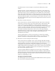
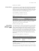
Figure 24 Two typical L2TP Tunnel modes
1 Initiated by remote dial-up user. Remote system dials in LAC via PSTN/ISDN. LAC
sends Tunnel setup request to LNS through the Internet. Dial-up users’ addresses
are assigned by LNS. The authentication and accounting of remote dial-up users
can be accomplished either by LAC side as an agent or by LNS side directly.
2 Initiated directly by LAC users (local users who support L2TP). Once assigned a
public network address, an LAC user can send Tunnel setup request directly to
LNS, without requiring an additional LAC device. In this case, the private network
address of an LAC user is assigned by LNS.
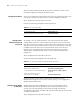
Call setup flow of L2TP Tunnel
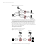
Typical L2TP application network is as follows:
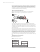
Figure 25 Typical L2TP application network
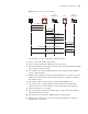
Call setup flow of L2TP Tunnel is shown in the following figure:
Internet
Remote system
PSTN/ISDN
Internal server
LAC
LNS
Frame Relay
or ATM
LAC
LNS
LAC client
Internal server
Internet
Remote system
PSTN/ISDN
Internal server
LAC
LNS
Frame Relay
or ATM
LAC
LNS
LAC client
Internal server
PC
PSTN/ISDN WAN
IP network
RADIUS Server
IP network
RADIUS Server
PC
PC
Switch8800A
LAC
Switch8800B
LNS