
3Com Switch 8800 Family IPsec Module Configuration and Command reference Guide

124 CHAPTER 8: CONFIGURATION OF L2TP
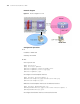
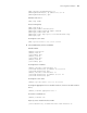
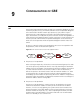
Network diagram
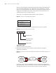
Figure 27 Network diagram for L2TP
Configuration procedure
1 PC
IP address: 10.0.0.1/24
Gateway: 10.0.0.254
2 NAS
# Set a system user.
<NAS> system-view
[NAS] local-user vpdnuser
[NAS-luser-vpdnuser] password simple Hello
[NAS-luser-vpdnuser] service-type ppp
[NAS-luser-vpdnuser] quit
# Configure a virtual template interface.
[NAS] interface Virtual-Template 0
[NAS-Virtual-Template0] ppp authentication-mode pap
[NAS-Virtual-Template0] quit
# Bind the virtual template interface to the Ethernet interface.
[NAS] interface GigabitEthernet 0/0
[NAS-GigabitEthernet0/0] pppoe-server bind virtual-template 0
[NAS-GigabitEthernet0/0] quit
# Configure the Ethernet interface connected to the LNS.
10.0.0.1/24
Switch 8800