
3Com Switch 8800 Family IPsec Module Configuration and Command reference Guide

136 CHAPTER 9: CONFIGURATION OF GRE
Displaying and
Debugging GRE
Upon the completion of the above configurations, execute the display command
in any view to view their running state and to verify the effect of the
configurations. The debugging command can be used in user view.
GRE Configuration
Example
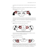
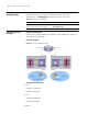
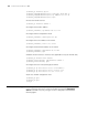
Network requirements
A GRE Tunnel is established between SecBlade_A and SecBlade_B so that PC_A
and PC_B can be connected.
Network diagram
Figure 35 Network diagram for GRE
Configuration procedure
1 PC A
IP address: 10.0.0.1/24
Gateway: 10.0.0.254
2 PC B
IP address: 20.0.0.1/24
Gateway: 20.0.0.254
3 Router
Tabl e 126 Display and debug GRE
Operation Command
Display operating state of Tunnel interfaces display interface tunnel number
Enable Tunnel information debugging debugging tunnel
Switch 8800A
Switch 8800B