
3Com Switch 8800 Family IPsec Module Configuration and Command reference Guide

232 CHAPTER 15: VRRP CONFIGURATIONS
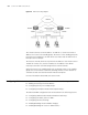
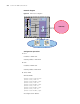
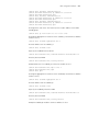
Figure 48 VRRP networking diagram
This virtual router has its own IP address: 10.100.10.1 (it can be the interface
address on a router in the standby group). The routers in the standby group also
have their own IP addresses: 10.100.10.2 for the master and 10.100.10.3 for a
backup router for example.
The hosts on the LAN, however only know the IP address of this virtual router or
10.100.10.1 and as such, use this IP address as the address of the default
next-hop router when communicating with the external network.
When the master in the standby group fails, the backup routers in the standby
group elects a new master to take over, allowing the hosts on the network to
communicate with the external network without interruption.
For more information about VRRP, refer to RFC 2338.
Configuring VRRP The basic VRRP configuration tasks are described in the following sections:
■ “Adding or Deleting a Virtual IP Address”
■ “Configuring Priority in a Standby Group”
■ “Configuring Preemption Mode and Preemption Delay”
The advanced VRRP configuration tasks are described in the following sections:
■ “Configuring Authentication Mode and Authentication Key”
■ “Configuring the Adver_Timer of VRRP”
■ “Configuring Interface Tracking”
■ “Enabling/Disabling Virtual IP Address Pinging”
■ “Enabling/Disabling TTL Check for VRRP Packets”