
3Com Switch 8800 Family IPsec Module Configuration and Command reference Guide

Displaying and Debugging VRRP 237
By default, the backup switch checks the TTL value for VRRP packets.
Displaying and
Debugging VRRP
After completing the above configurations, you may execute the display
command in any view to view the operating state about VRRP after VRRP
configuration, and to verify the effect of the configurations.
Execute the debugging command in user view.
You may enable/disable VRRP packet debugging and VRRP state debugging to
check VRRP debugging state.
By default, the debugging for VRRP is disabled.
VRRP Configuration
Examples
VRRP Single Standby
Group Example 1
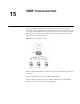
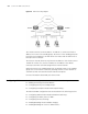
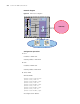
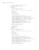
Network requirements
As shown in Figure 49, insert two IPsec modules into an Switch 8807. Two IPsec
modules run VRRP and a virtual IP address is provided for the switch to implement
redundant backup. In normal case, the data stream to the Internet passes by
secblade_A. When secblade_A fails, all data stream to the Internet passes by
secblade_B.
Tab le 255 Display and debug VRRP
Operation Command
Display state information about VRRP.
display vrrp [ interface type number [
virtual-router-ID ] ]
Enable VRRP packet debugging. debugging vrrp packet
Disable VRRP packet debugging. undo debugging vrrp packet
Enable VRRP state debugging. debugging vrrp state
Disable VRRP state debugging. undo debugging vrrp state