
3Com Switch 8800 Family IPsec Module Configuration and Command reference Guide

238 CHAPTER 15: VRRP CONFIGURATIONS
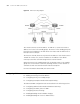
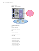
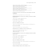
Network diagram
Figure 49 VRRP network diagram
Configuration procedure
1 PC A
IP address: 10.0.0.1/24.
Gateway address: 10.0.0.254.
2 PC B
IP address: 20.0.0.1/24.
Gateway address: 20.0.0.254.
3 Switch 8807
# Divide VLANs.
<Switch 8807> system-view
[Switch 8807] vlan 10
[Switch 8807-vlan10] quit
[Switch 8807] vlan 20
[Switch 8807-vlan20] quit
[Switch 8807] vlan 30
[Switch 8807-vlan30] quit
[Switch 8807] vlan 50
[Switch 8807-vlan50] quit
# Configure the IP address.
SecBlade_A
8800
Vlan10
Vlan 50
Internet
PC_A 10.0.0.1/24
PC_B 20.0.0.1/24
Vlan20
10.0.0.254/24
20.0.0.254/24
Vlan30
Vlan 50
Vlan 50
SecBlade_B
50.0.0.2/24
50.0.0.1/24
30.0.0.254
/24
30.0.0.1/24
30.0.0.2/24
Virtual IP
30.0.0.100/24