
3Com Switch 8800 Family IPsec Module Configuration and Command reference Guide


244 CHAPTER 15: VRRP CONFIGURATIONS
mode is configured for SecBlade_A to resume its gateway function as the Master
when it recovers.
Multi-Standby Group
Configuration Example
Network requirements
Such a multi-standby configuration can implement load sharing. SecBlade_A
serves as the Master of standby group 1 and simultaneously a backup of standby
group 2, while SecBlade_B is quite the contrary, serving as the Master of standby
group 2 but a backup of standby group 1. PC A shall take standby group 1 as its
gateway, and PC B takes standby group 2 as its gateway. In this way, both
purposes of data stream balancing and mutual standby are achieved.
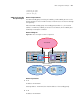
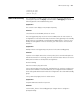
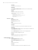
Network diagram
Figure 51 Network diagram for VRRP configuration
Configuration procedure
1 PC A
IP address: 10.0.0.50/24.
Gateway address: 10.0.0.253 (the virtual IP address of standby group 1)
2 PC B
IP address: 10.0.0.60/24.
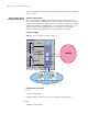
SecBlade
Vlan10
Vlan 50
Internet
PC_A 10.0.0.1/24
PC_B 20.0.0.1/24
Vlan20
10.0.0.254/24
20.0.0.254/24
Vlan30
Vlan 50
Vlan
50
_A
SecBlade
_B
50.0.0.2/24
50.0.0.1/24
30.0.0.254
/24
30.0.0.1/24
30.0.0.2/24
Virtual IP
30.0.0.100/24
Switch 8800