
3Com Switch 8800 Family IPsec Module Configuration and Command reference Guide


Fundamental Technology of VPN 99
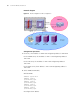
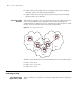
Figure 20 Diagram for VPN application
It can be seen that enterprise internal resource sharers can access local ISP at its
POP (Point of Presence) server via PSTN/ISDN network or local network and access
the internal resources of the company. With traditional WAN networking
technology, however, they need to be connected using dedicated lines to achieve
the same purpose. VPN allows remote end users and clients in other cities to
access enterprise internal resources without being authorized by their local ISPs,
which is of great significance for staffs on business trip and geographically
scattered clients.
An enterprise can deploy VPN services simply by setting up a VPN-supported server
for resource sharing (e.g. a Windows NT server or a router supporting VPN). The
resource sharers connect to local POP server via PSTN/ISDN or LAN before they
directly call the remote server (VPN server) of the enterprise. The call process is
completed by ISP Network Access Server (NAS) and VPN server together.
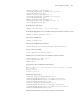
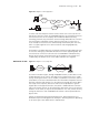
Mechanism of VPN Figure 21 Diagram for accessing VPN
As shown in the above figure, through PSTN/ISDN network, a subscriber accesses
ISP NAS (Network Access Server). After NAS server recognizes that this is a VPN
user by checking user name or access number, it establishes a connection, which is
called Tunnel, to the user’s destination VPN server. Then NAS encapsulates the user
data into IP packets and transmits it to the VPN server through this Tunnel. Upon
the receipt of this IP packet, VPN server removes the encapsulation to get the
original data. In the opposite direction, the packet is handled likewise. On both
sides of the Tunnel, packets can be encrypted to make other users on the Internet
unable to access them, so they are safe and authentic. For users, Tunnels are only
the logical extension of their PSTN/ISDN links and thus can be operated like the
physical links.
Tunnels are implemented using Tunneling protocols. Tunneling protocols are
divided into layer 2 Tunneling protocols and layer 3 Tunneling protocols depending
on at which layer of OSI model Tunnel is implemented.
POP
POP
POP
PC
PSTN/ISDN
Cooperator
Remote
Subscriber
Internet
ISP IP
Frame Relay
ATM
Corporate
Headquarter
Internal Server
VPN
Subscriber
PSTN/ISDN
NAS
VPN Server