H3C S7500 Series Ethernet Switches Command Manual Hangzhou H3C Technologies Co., Ltd. http://www.h3c.com Manual Version: T2-08193F-20070720-C-1.
Copyright © 2006-2007, Hangzhou H3C Technologies Co., Ltd. All Rights Reserved No part of this manual may be reproduced or transmitted in any form or by any means without prior written consent of Hangzhou H3C Technologies Co., Ltd. Trademarks H3C, , Aolynk, , H3Care, , TOP G, , IRF, NetPilot, Neocean, NeoVTL, SecPro, SecPoint, SecEngine, SecPath, Comware, Secware, Storware, NQA, VVG, V2G, VnG, PSPT, XGbus, N-Bus, TiGem, InnoVision and HUASAN are trademarks of Hangzhou H3C Technologies Co., Ltd.
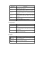
About This Manual Related Documentation In addition to this manual, each H3C S7500 Series Ethernet Switches documentation set includes the following: Manual Description H3C S7500 Series Ethernet Switches Operation Manual It is used for assisting the users in data configurations and typical applications. H3C S7500 Series Ethernet Switches Installation Manual It provides information for the system installation.
Part Contents 10 Link Aggregation Introduces the commands used for link aggregation. 11 Port Isolation Introduces the commands used for port isolation. 12 Port Binding Introduces the commands used for port binding. 13 DLDP Introduces the commands used for DLDP configuration. 14 MAC Address Table Introduces the commands used for MAC address forwarding table management. 15 MSTP Introduces the STP-related commands and VLAN-VPN tunnel-related commands.
Part Contents 30 SNMP-RMON Introduces the commands used for SNMP and RMON configuration. 31 NTP Introduces the NTP-related commands. 32 SSH Terminal Service Introduces the commands used for SSH and SFTP configuration. 33 File System Management Introduces the commands used for file system management. 34 FTP and TFTP Introduces commands. 35 Information Center Introduces the commands used for information center configuration. 36 DNS Introduces the DNS-related commands.
Convention Description { x | y | ... } Alternative items are grouped in braces and separated by vertical bars. One is selected. [ x | y | ... ] Optional alternative items are grouped in square brackets and separated by vertical bars. One or none is selected. { x | y | ... } * Alternative items are grouped in braces and separated by vertical bars. A minimum of one or a maximum of all can be selected. [ x | y | ...
Command Manual – CLI H3C S7500 Series Ethernet Switches Table of Contents Table of Contents Chapter 1 CLI Configuration Commands.................................................................................... 1-1 1.1 CLI Configuration Commands ........................................................................................... 1-1 1.1.1 command-privilege level ......................................................................................... 1-1 1.1.2 display history-command ............
Command Manual – CLI H3C S7500 Series Ethernet Switches Chapter 1 CLI Configuration Commands Chapter 1 CLI Configuration Commands 1.1 CLI Configuration Commands 1.1.1 command-privilege level Syntax command-privilege level level view view command undo command-privilege view view command View System view Parameters level: Command Level. This argument ranges from 0 to 3. view: Command view. This argument can be any command view the switch supports. command: Command to be specified.
Command Manual – CLI H3C S7500 Series Ethernet Switches Chapter 1 CLI Configuration Commands 1.1.2 display history-command Syntax display history-command View Any view Parameters None Description Use the display history-command command to display history commands. All the history commands are saved in the history command cache. When the history command cache is full, the old information in it will be overwritten. Related commands: history-command max-size. Examples # Display history commands.
Command Manual – CLI H3C S7500 Series Ethernet Switches Chapter 1 CLI Configuration Commands well to switch to the higher user level. You will remain in the original user level if you fail to provide the correct password. Note that: z Users logging into a switch also fall into four levels, each of which corresponds to one of the command levels. Users at a specific level can only use the commands at the same level and the commands at the lower levels.
Command Manual – CLI H3C S7500 Series Ethernet Switches Chapter 1 CLI Configuration Commands password: Password to be set. If you specify the simple keyword, you can provide this argument in plain text. If you specify the cipher keyword, you can provide this argument in either encrypted text or plain text.
Command Manual – Login H3C S7500 Series Ethernet Switches Table of Contents Table of Contents Chapter 1 Login Commands ........................................................................................................ 1-1 1.1 Login Commands............................................................................................................... 1-1 1.1.1 authentication-mode................................................................................................ 1-1 1.1.
Command Manual – Login H3C S7500 Series Ethernet Switches Chapter 1 Login Commands Chapter 1 Login Commands 1.1 Login Commands 1.1.1 authentication-mode Syntax authentication-mode { password | scheme [ command-authorization ] | none } View User interface view Parameters password: Authenticates users with the local password. scheme: Authenticates users locally or remotely with usernames and passwords. command-authorization: Performs command authorization on TACACS authentication server.
Command Manual – Login H3C S7500 Series Ethernet Switches Chapter 1 Login Commands Examples # Configure to authenticate users with local password on the AUX interface. system-view System View: return to User View with Ctrl+Z. [H3C] user-interface aux 0 [H3C-ui-aux0] authentication-mode password 1.1.2 auto-execute command Syntax auto-execute command text undo auto-execute command View User interface view Parameters text: Command to be executed automatically.
Command Manual – Login H3C S7500 Series Ethernet Switches Chapter 1 Login Commands Examples # Configure the telnet 10.110.100.1 command to be executed automatically after users log into VTY 0. system-view System View: return to User View with Ctrl+Z. [H3C] user-interface vty 0 [H3C-ui-vty0] auto-execute command telnet 10.110.100.1 % This action will lead to configuration failure through ui-vty0. Are you sure?[Y/N]y 1.1.
Command Manual – Login H3C S7500 Series Ethernet Switches Chapter 1 Login Commands View Any view Parameters type: User interface type. number: User interface index. summary: Displays the summary information about a user interface. Description Use the display user-interface command to display the information about a specified user interface or all user interfaces.
Command Manual – Login H3C S7500 Series Ethernet Switches Chapter 1 Login Commands Filed Description Tx/Rx Transmission speed of the user interface Modem Indicates whether or not a modem is used. Privi Available command level Auth Authentication mode Int Physical position of the user interface A The current user is authenticated by AAA. N The current user needs not to be authenticated. P The current user needs to provide the password to pass the authentication.
Command Manual – Login H3C S7500 Series Ethernet Switches Chapter 1 Login Commands Examples # Display the usage information about the current user interface. display users UI F 0 1 AUX 0 VTY 0 Delay Type Ipaddress Username Userlevel 00:00:00 00:06:08 TEL 3 192.168.0.3 + : Current operation user. F : Current operation user work in async mode.
Command Manual – Login H3C S7500 Series Ethernet Switches Chapter 1 Login Commands Description Use the flow-control command to configure the flow control mode of the user interface. Use the undo flow-control command to restore the default flow control mode of the user interface. By default, flow control is not performed. This command can be executed in AUX user interface view only. Examples # Set flow control mode to software flow control. system-view System View: return to User View with Ctrl+Z.
Command Manual – Login H3C S7500 Series Ethernet Switches Chapter 1 Login Commands After you execute this command, user interface VTY 0 will be disconnected. The user in it must log in again to connect to the switch. 1.1.8 header Syntax header [ incoming | login | shell ] text undo header { incoming | login | shell } View System view Parameters incoming: Sets the incoming banner for users that log in through modems.
Command Manual – Login H3C S7500 Series Ethernet Switches Chapter 1 Login Commands You can specify the banner in the following three ways, each of which requires that the first character and the last character of the banner be the same. z Enter the banner in multiple lines. If you only type one character in the first line of a banner, the character and the last character do not act as part of the banner. The following gives an example of this way.
Command Manual – Login H3C S7500 Series Ethernet Switches Chapter 1 Login Commands (The beginning and end characters of the banner are not displayed.) Option 2: Enter the banner in multiple lines. system-view System View: return to User View with Ctrl+Z. [H3C] header shell %SHELL: (Following appears after you press :) Input banner text, and quit with the character '%'.
Command Manual – Login H3C S7500 Series Ethernet Switches Chapter 1 Login Commands Use the undo history-command max-size command to revert to the default history command buffer size. Examples # Set the size of the history command buffer of AUX 0 to 20, that is, the history command buffer of AUX 0 can store up to 20 commands. system-view System View: return to User View with Ctrl+Z. [H3C] user-interface aux 0 [H3C-ui-aux0] history-command max-size 20 1.1.
Command Manual – Login H3C S7500 Series Ethernet Switches Chapter 1 Login Commands 1.1.11 lock Syntax lock View User view Parameters None Description Use the lock command to lock the current user interface to prevent unauthorized operations in the user interface. With the execution of this command, the system prompts to enter and confirm the password, and then locks the user interface. The password the system can identify is in the range of 1 to 16 characters.
Command Manual – Login H3C S7500 Series Ethernet Switches Chapter 1 Login Commands Description Use the modem command to configure the call in and call out attribute of the Modem. Use the undo modem command to disable the call in and call out configuration. Both call in and call out are allowed when the modem command is executed without any keyword. Both call in and call out are disabled when the undo modem command is executed without any keyword.
Command Manual – Login H3C S7500 Series Ethernet Switches Chapter 1 Login Commands [H3C] user-interface aux 0 [H3C>-ui-aux0] modem auto-answer 1.1.14 modem timer answer Syntax modem timer answer seconds undo modem timer answer View User interface view Parameters seconds: Waiting timeout time, in seconds, ranging from 1 to 60. The default timeout time is 30 seconds. Description Use the modem timer answer to configure the carrier detection timeout time after off-hook during call-in connection setup.
Command Manual – Login H3C S7500 Series Ethernet Switches Chapter 1 Login Commands none: Does not check. odd: Performs odd checks. space: Performs space checks. Description Use the parity command to set the check mode of the user interface. Use the undo parity command to revert to the default check mode. Use these two commands in AUX user interface view only. No check is performed by default. Examples # Set to perform even checks. system-view System View: return to User View with Ctrl+Z.
Command Manual – Login H3C S7500 Series Ethernet Switches Chapter 1 Login Commands System View: return to User View with Ctrl+Z. [H3C] user-interface vty 0 [H3C-ui-vty0] protocol inbound ssh 1.1.17 screen-length Syntax screen-length screen-length undo screen-length View User interface view Parameters screen-length: Number of lines the screen can contain. This argument ranges from 0 to 512 and defaults to 24.
Command Manual – Login H3C S7500 Series Ethernet Switches Chapter 1 Login Commands Parameters all: Sends messages to all user interfaces. type: User interface type. number: Absolute or relative index of the user interface. Description Use the send command to send messages to a specified user interface or all user interfaces. Examples # Send hello to all user interfaces. send all Enter message, end with CTRL+Z or Enter; abort with CTRL+C: hello^Z Send message? [Y/N]y 1.1.
Command Manual – Login H3C S7500 Series Ethernet Switches Chapter 1 Login Commands Description Use the service-type command to specify the login type and the corresponding available command level. Use the undo service-type command to cancel login type configuration.
Command Manual – Login H3C S7500 Series Ethernet Switches Chapter 1 Login Commands telnet Establish one TELNET connection tracert Trace route function undo Cancel current setting 1.1.20 set authentication password Syntax set authentication password { cipher | simple } password undo set authentication password View User interface view Parameters cipher: Specifies to display the local password in encrypted text when you display the current configuration.
Command Manual – Login H3C S7500 Series Ethernet Switches Chapter 1 Login Commands Examples # Set the local password of VTY 0 to 123. system-view System View: return to User View with Ctrl+Z. [H3C] user-interface vty 0 [H3C-ui-vty0] set authentication password simple 123 1.1.21 shell Syntax shell undo shell View User interface view Parameters None Description Use the shell command to make terminal services available for the user interface(s).
Command Manual – Login H3C S7500 Series Ethernet Switches Chapter 1 Login Commands 1.1.22 speed Syntax speed speed-value undo speed View User interface view Parameters speed-value: Transmission speed (in bps). This argument can be 300, 600, 1200, 2400, 4800, 9600, 19,200, 38,400, 57,600, and 115,200 and defaults to 9,600. Description Use the speed command to set the transmission speed of the user interface. Use the undo speed command to revert to the default transmission speed.
Command Manual – Login H3C S7500 Series Ethernet Switches Chapter 1 Login Commands Description Use the stopbits command to set the stop bits of the user interface. Use the undo stopbits command to revert to the default stop bits. Use these two commands in the AUX user interface only. By default, the stop bits is 1. Note: Changing the value of the stop bits does not affect the communications between the switch and the terminal. Examples # Set the stop bits to 2.
Command Manual – Login H3C S7500 Series Ethernet Switches Chapter 1 Login Commands Examples # Set the domain name of the switch to ABC. system-view System View: return to User View with Ctrl+Z. [H3C] sysname ABC [ABC] 1.1.25 telnet Syntax telnet { hostname | ip-address } [ service-port ] View User view Parameters hostname: Host name of the remote switch. You can use the ip host command to assign a host name to a switch. ip-address: IP address of the remote switch.
Command Manual – Login H3C S7500 Series Ethernet Switches Chapter 1 Login Commands 1.1.26 user-interface Syntax user-interface [ type ] first-number [ last-number ] View System view Parameters type: User interface type. first-number: User interface index, which identifies the first user interface to be configured. last-number: User interface index, which identifies the last user interface to be configured.
Command Manual – Login H3C S7500 Series Ethernet Switches Chapter 1 Login Commands Use the undo user privilege level command to revert to the default command level. By default, the commands of level 3 are available to the users logging into the AUX user interface. The commands of level 0 are available to the users logging into VTY user interfaces. Examples # Configure that commands of level 0 are available to the users logging into VTY 0. system-view System View: return to User View with Ctrl+Z.
Command Manual – Login H3C S7500 Series Ethernet Switches Chapter 2 Commands for User Control Chapter 2 Commands for User Control 2.1 Commands for Controlling Logging in Users 2.1.1 acl Syntax acl acl-number { inbound | outbound } undo acl { inbound | outbound } View User interface view Parameters acl-number: ACL number ranging from 2,000 to 3,999. inbound: Filters the users Telneting to the current switch. outbound: Filters the users Telneting to other switches from the current switch.
Command Manual – Login H3C S7500 Series Ethernet Switches Chapter 2 Commands for User Control View System view Parameters read: Specifies that the community has read-only permission in the specified view. write: Specifies that the community has read/write permission in the specified view. community-name: Community name. A string ranges from 1 to 32 characters. mib-view: Sets the name of the MIB view accessible to the community. view-name: MIB view name, 1 to 32 characters long.
Command Manual – Login H3C S7500 Series Ethernet Switches Chapter 2 Commands for User Control View System view Parameters v1: Specifies to adopt v1 security scheme. v2c: Specifies to adopt v2c security scheme. v3: Specifies to adopt v3 security scheme. group-name: Group name. This argument can be of 1 to 32 characters. authentication: Specifies to authenticate SNMP data without encrypting the data. privacy: Authenticates and encrypts packets. read-view: Sets a read-only view.
Command Manual – Login H3C S7500 Series Ethernet Switches Chapter 2 Commands for User Control 2.1.
Command Manual – Login H3C S7500 Series Ethernet Switches Chapter 2 Commands for User Control Use the undo snmp-agent usm-user command to remove a user from the corresponding SNMP group. The operation also frees the user from the corresponding ACL-related configuration.
Command Manual – Configuration File Management H3C S7500 Series Ethernet Switches Table of Contents Table of Contents Chapter 1 Configuration File Management Commands ............................................................ 1-1 1.1 Configuration File Management Commands ..................................................................... 1-1 1.1.1 display current-configuration ................................................................................... 1-1 1.1.2 display saved-configuration....
Command Manual – Configuration File Management H3C S7500 Series Ethernet Switches Chapter 1 Configuration File Management Commands Chapter 1 Configuration File Management Commands 1.1 Configuration File Management Commands 1.1.
Command Manual – Configuration File Management H3C S7500 Series Ethernet Switches Chapter 1 Configuration File Management Commands exclude: Displays the configuration excluding the specified characters. include: Displays the configuration including the specified characters. text: Text included in a configuration item, expressed in a regular expression. .
Command Manual – Configuration File Management H3C S7500 Series Ethernet Switches Chapter 1 Configuration File Management Commands Related commands: save, reset saved-configuration, display saved-configuration. Examples # View the running configuration parameters of the switch. display current-configuration # sysname H3C # radius scheme system primary authentication 127.0.0.1 1645 primary accounting 127.0.0.
Command Manual – Configuration File Management H3C S7500 Series Ethernet Switches Chapter 1 Configuration File Management Commands speed 1000 port access vlan 2 # interface Ethernet3/0/2 # interface Ethernet3/0/3 # interface Ethernet3/0/4 # interface Ethernet4/0/1 port access vlan 2 # interface Ethernet4/0/2 # interface Ethernet4/0/3 # interface Ethernet4/0/4 # interface NULL0 # ospf # area 0.0.0.0 network 10.1.1.0 0.0.0.
Command Manual – Configuration File Management H3C S7500 Series Ethernet Switches Chapter 1 Configuration File Management Commands primary authentication 127.0.0.1 1645 primary accounting 127.0.0.1 1646 local-server nas-ip 127.0.0.1 key hello vlan 1 interface Vlan-interface1 ip address 10.1.1.2 255.255.255.0 interface Ethernet3/0/1 speed 1000 interface Ethernet4/0/1 network 10.1.1.0 0.0.0.255 # View configuration information beginning with “user”.
Command Manual – Configuration File Management H3C S7500 Series Ethernet Switches Chapter 1 Configuration File Management Commands network 10.1.1.0 0.0.0.255 # user-interface aux 0 user-interface vty 0 4 # return 1.1.2 display saved-configuration Syntax display saved-configuration View Any view Parameters None Description Use the display saved-configuration command to view the configuration files saved in the Flash memory of the Ethernet switch.
Command Manual – Configuration File Management H3C S7500 Series Ethernet Switches Chapter 1 Configuration File Management Commands idle-cut disable domain default enable system # local-server nas-ip 127.0.0.1 key hello # router id 2.2.2.2 # stp timer hello 500 # vlan 1 # vlan 2 # interface Vlan-interface1 # interface Vlan-interface2 ip address 10.1.1.2 255.255.255.
Command Manual – Configuration File Management H3C S7500 Series Ethernet Switches Chapter 1 Configuration File Management Commands interface NULL0 # ospf # area 0.0.0.0 network 10.1.1.0 0.0.0.255 # user-interface aux 0 user-interface vty 0 4 # return The configurations listed above are global configuration, port configuration and user interface configuration successively. 1.1.
Command Manual – Configuration File Management H3C S7500 Series Ethernet Switches Chapter 1 Configuration File Management Commands Examples # Display the running configuration parameters in system view. system-view System View: return to User View with Ctrl+Z. [H3C] display this # sysname H3C # super password level 3 simple 1234567890 # ftp server enable # domain default enable system # dhcp-server 2 ip 1.1.1.1 # undo info-center enable # router id 1.1.1.
Command Manual – Configuration File Management H3C S7500 Series Ethernet Switches Chapter 1 Configuration File Management Commands Parameters None Description Use the display startup command to display the configuration file names used for the current and the next start-ups. Related commands: startup saved-configuration. Examples # Display the configuration file names used for the current and the next start-ups. display startup MainBoard: Startup saved-configuration file: flash:/config.
Command Manual – Configuration File Management H3C S7500 Series Ethernet Switches Related commands: Chapter 1 Configuration File Management Commands save, display current-configuration, display saved-configuration. Examples # Remove the configuration files from the Flash memory of the Ethernet switch. reset saved-configuration The saved configuration will be erased. Are you sure?[Y/N]y Configuration in flash memory is being cleared. Please wait ... ....
Command Manual – Configuration File Management H3C S7500 Series Ethernet Switches Chapter 1 Configuration File Management Commands You are recommended to adopt the fast saving mode in the conditions of stable power and adopt the safely saving mode in the conditions of unstable power or remote maintenance. Related commands: reset saved-configuration, display current-configuration, display saved-configuration. Examples # Save the current configuration files to the Flash memory.
Command Manual – VLAN H3C S7500 Series Ethernet Switches Table of Contents Table of Contents Chapter 1 VLAN Configuration Commands................................................................................ 1-1 1.1 VLAN Configuration Commands........................................................................................ 1-1 1.1.1 broadcast-suppression............................................................................................ 1-1 1.1.2 description .............................
Command Manual – VLAN H3C S7500 Series Ethernet Switches Chapter 1 VLAN Configuration Commands Chapter 1 VLAN Configuration Commands 1.1 VLAN Configuration Commands 1.1.1 broadcast-suppression Syntax broadcast-suppression { ratio | pps pps } undo broadcast-suppression View VLAN view Parameters ratio: Maximum bandwidth ratio of broadcast traffic allowed in the specified VLAN. Its value ranges from 1 to 100 and defaults to 100.
Command Manual – VLAN H3C S7500 Series Ethernet Switches Chapter 1 VLAN Configuration Commands Table 1-1 Broadcast storm suppression modes and card types Broadcast storm suppression mode Type A card Non-type-A card VLAN pps suppression Supported Not supported VLAN bandwidth ratio suppression Supported Not supported Note: Type A cards include LS81FT48A, LS81FM24A, LS81FS24A, LS81GB8UA, LS81GT8UA, iSalience I, Salience I and Salience II.
Command Manual – VLAN H3C S7500 Series Ethernet Switches Chapter 1 VLAN Configuration Commands Description Use the description command to set the description string or text for the current VLAN or VLAN interface. Use the undo description command to restore the default description string or text. By default, the description string of a VLAN is its VLAN ID, for example, ”VLAN 0001”; the descriptive text of a VLAN interface is its name, for example, “Vlan-interface 1 Interface”.
Command Manual – VLAN H3C S7500 Series Ethernet Switches Chapter 1 VLAN Configuration Commands Vlan-interface2 current state :DOWN Line protocol current state :DOWN IP Sending Frames' Format is PKTFMT_ETHNT_2, Hardware address is 0012-a990-2241 Internet Address is 10.1.1.
Command Manual – VLAN H3C S7500 Series Ethernet Switches Chapter 1 VLAN Configuration Commands If the vlan-id argument or the all keyword is specified, the information about the specified VLANs or all VLANs is displayed, including VLAN ID, VLAN type (dynamic or static), routing function status (If enabled, the primary IP address and mask are displayed), VLAN description and VLAN name, VLAN broadcast storm suppression ratio, and VLAN member ports.
Command Manual – VLAN H3C S7500 Series Ethernet Switches Chapter 1 VLAN Configuration Commands 1.1.5 interface Vlan-interface Syntax interface Vlan-interface vlan-id undo interface Vlan-interface vlan-id View System view Parameters vlan-id: ID of the VLAN interface, in the range of 1 to 4,094. Description Use the interface Vlan-interface command to create a VLAN interface or enter VLAN interface view. Use the undo interface Vlan-interface command to delete the VLAN interface.
Command Manual – VLAN H3C S7500 Series Ethernet Switches Chapter 1 VLAN Configuration Commands By default, the name of a VLAN is its VLAN ID, for example, “VLAN 0001”. Examples # Specify the name of VLAN 2 as hello. system-view System View: return to User View with Ctrl+Z. [H3C] vlan 2 [H3C-vlan2] name hello 1.1.7 shutdown Syntax shutdown undo shutdown View VLAN interface view Parameters None Description Use the shutdown command to disable a VLAN interface.
Command Manual – VLAN H3C S7500 Series Ethernet Switches Chapter 1 VLAN Configuration Commands [H3C] interface Vlan-interface 2 [H3C-Vlan-interface2] shutdown [H3C-Vlan-interface2] undo shutdown 1.1.8 vlan Syntax vlan vlan-id undo vlan { vlan-id [ to vlan-id ] | all } View System view Parameters vlan-id: ID of the VLAN that you want to enter. Its value ranges from 1 to 4,094. to: Specifies the range of VLANs to be removed. all: Specifies to remove all VLANs.
Command Manual – VLAN H3C S7500 Series Ethernet Switches Chapter 1 VLAN Configuration Commands [H3C] vlan 1 [H3C-vlan1] 1.2 Port-Based VLAN Configuration Commands 1.2.1 port Syntax port interface-list undo port interface-list View VLAN view Parameters interface-list: List of Ethernet ports to be added to or removed from a VLAN.
Command Manual – VLAN H3C S7500 Series Ethernet Switches Chapter 1 VLAN Configuration Commands system-view System View: return to User View with Ctrl+Z. [H3C] vlan 2 [H3C-vlan2] port Ethernet2/0/1 to Ethernet2/0/3 1.2.2 port access vlan Syntax port access vlan vlan-id undo port access vlan View Ethernet port view Parameters vlan-id: VLAN ID defined in IEEE802.1Q, in the range of 2 to 4,094. Description Use the port access vlan command to add the access port into the specified VLAN.
Command Manual – VLAN H3C S7500 Series Ethernet Switches Chapter 1 VLAN Configuration Commands Description Use the port hybrid pvid vlan command to set the default VLAN ID for the hybrid port. Use the undo port hybrid pvid command to restore the default VLAN ID of the hybrid port. Set the default VLAN ID of the local hybrid port to the same value as that of the hybrid port on the peer switch. Otherwise, packets cannot be forwarded properly. Related commands: port link-type.
Command Manual – VLAN H3C S7500 Series Ethernet Switches Chapter 1 VLAN Configuration Commands The VLAN specified by the vlan-id argument must be existing. Otherwise, this command is invalid. Related commands: port link-type. Examples # Add the hybrid port Ethernet 2/0/1 to VLAN 2, VLAN 4 and VLAN 50 through VLAN 100, and configure the port to keep the VLAN tags of packets of these VLANs when it sends the packets. system-view System View: return to User View with Ctrl+Z.
Command Manual – VLAN H3C S7500 Series Ethernet Switches Chapter 1 VLAN Configuration Commands system-view System View: return to User View with Ctrl+Z. [H3C] interface Ethernet2/0/1 [H3C-Ethernet2/0/1] port link-type trunk 1.2.6 port trunk permit vlan Syntax port trunk permit vlan { vlan-id-list | all } undo port trunk permit vlan { vlan-id-list | all } View Ethernet port view Parameters vlan-id-list: VLAN range to which the trunk port will be added.
Command Manual – VLAN H3C S7500 Series Ethernet Switches Chapter 1 VLAN Configuration Commands Please wait... Done. 1.2.7 port trunk pvid vlan Syntax port trunk pvid vlan vlan-id undo port trunk pvid View Ethernet port view Parameters vlan-id: VLAN ID defined in IEEE802.1Q, in the range of 1 to 4094. It is 1 by default. Description Use the port trunk pvid vlan command to set the default VLAN ID for the trunk port. Use the undo port trunk pvid command to restore the default setting.
Command Manual – VLAN H3C S7500 Series Ethernet Switches Chapter 1 VLAN Configuration Commands Parameters interface-type interface-number [ to interface-type interface-number ]: Specifies the port number of the protocol to be displayed. If you do not use the to keyword, only one port is specified. If you use the to keyword, multiple contiguous ports are specified. The interface-type argument refers to the port type and the interface-number argument refers to the port number.
Command Manual – VLAN H3C S7500 Series Ethernet Switches Chapter 1 VLAN Configuration Commands Description Use the display protocol-vlan slot command to display information about the protocol-based VLAN on the specified card, including VLAN ID, protocol index and protocol type. Examples # Display information about protocol-based VLANs on all cards. display protocol-vlan slot all Slot: 0 VLAN ID Protocol-Index Protocol-Type 4 0 ip 10.1.1.1 255.255.255.0 4 1 ip 192.168.1.1 255.0.0.
Command Manual – VLAN H3C S7500 Series Ethernet Switches Chapter 1 VLAN Configuration Commands 0 ip 1.1.1.0 255.255.255.0 VLAN ID: 20 VLAN Type: Protocol-based VLAN Protocol Index Protocol Type 0 ip 192.168.0.0 255.255.255.0 1 ipx ethernetii 2 snap etype 0x0abc 3 llc dsap 0xac ssap 0xbd 1.3.
Command Manual – VLAN H3C S7500 Series Ethernet Switches Chapter 1 VLAN Configuration Commands [H3C] interface Ethernet2/0/1 [H3C-Ethernet2/0/1] port hybrid protocol-vlan vlan 3 0 to 6 1.3.5 protocol-vlan vlan slot Syntax protocol-vlan vlan vlan-id { protocol-index [ to protocol-end ] | all } { slot slot-number | mainboard } undo protocol-vlan vlan vlan-id { protocol-index [ to protocol-end ] | all } { slot slot-number | mainboard } View System view Parameters vlan-id: VLAN ID, ranging from 1 to 4094.
Command Manual – VLAN H3C S7500 Series Ethernet Switches Chapter 1 VLAN Configuration Commands Table 1-4 Protocol-based VLAN creation commands on different cards Command description Type A card Non-type-A card Create protocol-based VLAN on specific card in system view. Not supported Supported (for all IP protocols and subnet IP protocols) Create protocol-based VLAN on specific port in Ethernet port view.
Command Manual – VLAN H3C S7500 Series Ethernet Switches Chapter 1 VLAN Configuration Commands ipx { ethernetii | llc | raw I snap }: Specifies IPX protocol-based VLAN. The ethernetii, llc, raw and snap keywords indicate four encapsulation types. mode: Specifies VLAN based on other protocol type and encapsulation format. ethernetii [ etype etype-id ]: Specifies EthernetII encapsulation-based VLAN.
Command Manual – VLAN H3C S7500 Series Ethernet Switches Chapter 1 VLAN Configuration Commands Caution: In a VLAN, it is not allowed to configure two templates with the same protocol type and encapsulation format. The encapsulation defined by a user-defined template is the same as that defined by a standard template if the parameters of the user-defined template adopt some special values. In this scenario, the user-defined template and the standard template cannot be configured in the same VLAN.
Command Manual – VLAN H3C S7500 Series Ethernet Switches Chapter 1 VLAN Configuration Commands # Cancel protocols 0 to 5 in VLAN 5.
Command Manual – Extended VLAN Application H3C S7500 Series Ethernet Switches Table of Contents Table of Contents Chapter 1 Voice VLAN Configuration Commands ..................................................................... 1-1 1.1 Voice VLAN Configuration Commands ............................................................................. 1-1 1.1.1 display voice vlan oui .............................................................................................. 1-1 1.1.
Command Manual – Extended VLAN Application H3C S7500 Series Ethernet Switches Chapter 1 Voice VLAN Configuration Commands Chapter 1 Voice VLAN Configuration Commands 1.1 Voice VLAN Configuration Commands 1.1.1 display voice vlan oui Syntax display voice vlan oui View Any view Parameters None Description Use the display voice vlan oui command to display the currently supported OUI addresses and the related information. Related commands: voice vlan, voice vlan enable.
Command Manual – Extended VLAN Application H3C S7500 Series Ethernet Switches Chapter 1 Voice VLAN Configuration Commands Parameters None Description Use the display voice vlan status command to display voice VLAN-related information, including voice VLAN status (disabled/enabled), security mode, aging time, port voice VLAN mode (manual mode or automatic mode), and so on. Related commands: voice vlan, voice vlan enable. Examples # Display information about the voice VLAN.
Command Manual – Extended VLAN Application H3C S7500 Series Ethernet Switches Chapter 1 Voice VLAN Configuration Commands Caution: The “Current voice vlan enable port mode” field lists the ports with the voice VLAN function enabled. Note that a port listed in this field may not currently operate in a voice VLAN. To check the ports operating in the current voice VLAN, use the display vlan command, which is described in section display vlan. 1.1.
Command Manual – Extended VLAN Application H3C S7500 Series Ethernet Switches Chapter 1 Voice VLAN Configuration Commands 1.1.4 voice vlan Syntax voice vlan vlan-id enable undo voice vlan enable View System view Parameters vlan-id: ID of the VLAN that needs to be enabled with the voice VLAN function, ranging from 2 to 4,094. Description Use the voice vlan command to enable the voice VLAN function globally. Use the undo voice vlan enable command to disable the voice VLAN function globally.
Command Manual – Extended VLAN Application H3C S7500 Series Ethernet Switches Chapter 1 Voice VLAN Configuration Commands Can't change voice vlan configuration when other voice vlan is running 1.1.5 voice vlan aging Syntax voice vlan aging minutes undo voice vlan aging View System view Parameters minutes: Aging time (in minutes) to be set for the voice VLAN. This argument ranges from 5 to 43,200 and defaults to 1,440.
Command Manual – Extended VLAN Application H3C S7500 Series Ethernet Switches Chapter 1 Voice VLAN Configuration Commands Use the undo voice vlan enable command to disable voice VLAN for a port. z The voice VLAN function takes effect on a port only when it is enabled in both system view and port view. z An access port whose voice VLAN mode is automatic does not support the voice vlan enable command. Related commands: display voice vlan status.
Command Manual – Extended VLAN Application H3C S7500 Series Ethernet Switches Chapter 1 Voice VLAN Configuration Commands Use the undo voice vlan mac-address command to disable a MAC address from being used to identify voice devices. A switch can use up to 16 MAC addresses to identify voice devices, including the five default OUI addresses (as listed in Table 1-2). When the number of MAC addresses reaches to 16, you will fail to add new MAC addresses.
Command Manual – Extended VLAN Application H3C S7500 Series Ethernet Switches Chapter 1 Voice VLAN Configuration Commands Use the undo voice vlan mode auto command to restore the voice VLAN mode of the port to manual mode. By default, the voice VLAN mode of the port is automatic mode. Related commands: display voice vlan status. Examples # Set the voice VLAN mode of GigabitEthernet 3/0/2 to manual. system-view System View: return to User View with Ctrl+Z.
Command Manual – Extended VLAN Application H3C S7500 Series Ethernet Switches Chapter 1 Voice VLAN Configuration Commands system-view System View: return to User View with Ctrl+Z.
Command Manual – Extended VLAN Application H3C S7500 Series Ethernet Switches Chapter 2 Isolate-User-VLAN Configuration Commands Chapter 2 Isolate-User-VLAN Configuration Commands Note: You need to configure the hybrid attribute for a port in the process of configuring an isolate-user-VLAN. For hybrid port-related commands, refer to the Port Basic Configuration part of the H3C S7500 Series Ethernet Switches Command Manual. 2.1 Isolate-User-VLAN Configuration Commands 2.1.
Command Manual – Extended VLAN Application H3C S7500 Series Ethernet Switches Chapter 2 Isolate-User-VLAN Configuration Commands Isolate-user-VLAN type : isolate-user-VLAN Route Interface: not configured Description: VLAN 0003 Tagged Ports: none Untagged Ports: Ethernet1/0/4 Ethernet1/0/8 Ethernet1/0/18 Vlan ID: 4 Vlan Type: static Private-vlan Type : Secondary Route Interface: not configured Description: VLAN 0004 Tagged Ports: none Untagged Ports: Ethernet1/0/4 Ethernet1/0/8 Vlan ID: 5 Vlan Typ
Command Manual – Extended VLAN Application H3C S7500 Series Ethernet Switches Chapter 2 Isolate-User-VLAN Configuration Commands Description Use the isolate-user-vlan command to establish the mapping between the isolate-user-VLAN and the secondary VLANs. Use the undo isolate-user-vlan command to cancel the mapping between the isolate-user-VLAN and the secondary VLANs.
Command Manual – Extended VLAN Application H3C S7500 Series Ethernet Switches Chapter 2 Isolate-User-VLAN Configuration Commands Caution: z Multiple isolate-user-VLANs can be configured for a switch. z You cannot configure isolate-user-VLAN for a switch that is enabled with GVRP. z You cannot enable both isolate-user-VLAN and super VLAN functions for one VLAN. If a VLAN is configured as an isolate-user-VLAN or a secondary VLAN, you cannot configure it as a super VLAN or a sub VLAN.
Command Manual – Extended VLAN Application H3C S7500 Series Ethernet Switches Chapter 3 Super VLAN Configuration Commands Chapter 3 Super VLAN Configuration Commands Note: Only Salience III series engines support this feature. 3.1 Super VLAN Configuration Commands 3.1.1 dhcp-server Syntax dhcp-server groupNo undo dhcp-server View VLAN interface view Parameters groupNo: DHCP server number, ranging from 0 to 19. Description Use the dhcp-server command to map the VLAN interface to a DHCP server group.
Command Manual – Extended VLAN Application H3C S7500 Series Ethernet Switches Chapter 3 Super VLAN Configuration Commands View Any view Parameters supervlan-id: ID of Super VLAN, range from 1 to 4,094. Description Use the display supervlan command to display the mapping between a Super VLAN and Sub VLANs, and the ports included in the sub VLANs. Related commands: supervlan, subvlan. Examples # Display the mapping relationship between Super VLAN 100 and the sub VLANs.
Command Manual – Extended VLAN Application H3C S7500 Series Ethernet Switches Chapter 3 Super VLAN Configuration Commands It is a Sub VLAN. And the Super VLAN is VLAN 100 ARP proxy disabled. Route Interface: not configured Description: VLAN 0102 Name: VLAN 0102 Broadcast MAX-ratio: 100 Tagged Ports: none Untagged Ports: Ethernet3/0/4 3.1.
Command Manual – Extended VLAN Application H3C S7500 Series Ethernet Switches Chapter 3 Super VLAN Configuration Commands Caution: z The sub VLANs must exist before you create mapping between the sub VLANs and the super VLAN. z After establishing the mapping between the sub VLANs and the super VLAN, you can still add (or remove) ports to (from) the sub VLANs. z The system allows for up to 1024 sub VLANs. Related commands: display supervlan.
Command Manual – Extended VLAN Application H3C S7500 Series Ethernet Switches z Chapter 3 Super VLAN Configuration Commands When a super VLAN exists, the proxy ARP function cannot be disabled on the corresponding VLAN interface. Related commands: display supervlan. Examples # Configure VLAN 2 to be a super VLAN. system-view System View: return to User View with Ctrl+Z.
Command Manual – IP Address-IP Performance-IPX H3C S7500 Series Ethernet Switches Table of Contents Table of Contents Chapter 1 IP Address Configuration Commands....................................................................... 1-1 1.1 IP Address Configuration Commands ............................................................................... 1-1 1.1.1 display ip interface .................................................................................................. 1-1 1.1.2 ip address.....
Command Manual – IP Address-IP Performance-IPX H3C S7500 Series Ethernet Switches Table of Contents 3.1.15 ipx route-static ..................................................................................................... 3-16 3.1.16 ipx sap disable..................................................................................................... 3-17 3.1.17 ipx sap gns-disable-reply .................................................................................... 3-17 3.1.
Command Manual – IP Address-IP Performance-IPX H3C S7500 Series Ethernet Switches Chapter 1 IP Address Configuration Commands Chapter 1 IP Address Configuration Commands 1.1 IP Address Configuration Commands 1.1.1 display ip interface Syntax display ip interface [ brief ] [ interface-type interface-number ] View Any view Parameters interface-type interface-number: interface-type indicates a port type and interface-number indicates a port number.
Command Manual – IP Address-IP Performance-IPX H3C S7500 Series Ethernet Switches Chapter 1 IP Address Configuration Commands Router advert: 0 Router solicit: 0 Time exceed: 0 IP header bad: 0 Timestamp request: 0 Timestamp reply: 0 Information request: 0 Information reply: 0 Netmask request: 0 Netmask reply: 0 Unknown type: 0 Table 1-1 Description on the fields of the display ip interface command Field Description Vlan-interface1 current state Current state of VLAN-interface 1 L
Command Manual – IP Address-IP Performance-IPX H3C S7500 Series Ethernet Switches Chapter 1 IP Address Configuration Commands Field Description ICMP packet input number: Echo reply: Unreachable: 0 0 0 Source quench: 0 Routing redirect: 0 Echo request: 0 Router advert: 0 Router solicit: Total number of received ICMP packets, including: 0 Time exceed: 0 IP header bad: 0 Timestamp request: Timestamp reply: 0 0 Information request: Information reply: Echo reply packet, unreachable packe
Command Manual – IP Address-IP Performance-IPX H3C S7500 Series Ethernet Switches Chapter 1 IP Address Configuration Commands By default, a VLAN or loopback interface has no IP address. Generally, it is enough to configure one IP address for a VLAN/LoopBack interface. However, you can configure up to eight IP addresses for a VLAN/LoopBack interface so that it can be connected to several subnets. Among these IP addresses, one is the primary IP address and all the others are secondary ones.
Command Manual – IP Address-IP Performance-IPX H3C S7500 Series Ethernet Switches Chapter 2 IP Performance Configuration Commands Chapter 2 IP Performance Configuration Commands 2.1 IP Performance Configuration Commands 2.1.1 display fib Syntax display fib fib-rule View Any view Parameters fib-rule: Specifies FIB entries that conform to specific rules. It can be a combination of multiple rules. The following table describes the combinations.
Command Manual – IP Address-IP Performance-IPX H3C S7500 Series Ethernet Switches Chapter 2 IP Performance Configuration Commands address/mask length, next hop, current flag, timestamp, and output interface. For the ACL configuration, refer to the ACL module of this manual. Examples # View all FIB entries. display fib Destination/Mask Nexthop Flag TimeStamp Interface 211.71.75.0/24 1.1.1.2 GSU t[250763] Vlan-interface2 1.1.2.1/32 127.0.0.1 GHU t[37] InLoopBack0 127.0.0.1/32 127.0.0.
Command Manual – IP Address-IP Performance-IPX H3C S7500 Series Ethernet Switches 211.71.75.0/24 Chapter 2 IP Performance Configuration Commands 1.1.1.2 GSU t[250763] Vlan-interface2 # View all the lines from the line containing the string 1.1.1.1. display fib | begin 1.1.1.1 1.1.1.1/32 127.0.0.1 GHU t[37] InLoopBack0 1.1.1.0/24 1.1.1.1 U t[37] Vlan-interface2 # View the total number of FIB entries. display fib statistics Route Entry Count : 30 2.1.
Command Manual – IP Address-IP Performance-IPX H3C S7500 Series Ethernet Switches Chapter 2 IP Performance Configuration Commands Table 2-3 Description on the fields of the display icmp statistics command Field Description bad formats Number of input packets in bad formats bad checksum Number of input packets with bad checksum echo Number of input/output echo request packets destination unreachable Number of input/output packets with unreachable destination source quench Number of input/output
Command Manual – IP Address-IP Performance-IPX H3C S7500 Series Ethernet Switches Chapter 2 IP Performance Configuration Commands Examples # Display the information about the socket of the TCP type. display ip socket socktype 1 SOCK_STREAM: Task = VTYD(18), socketid = 1, Proto = 6, LA = 0.0.0.0:23, FA = 0.0.0.
Command Manual – IP Address-IP Performance-IPX H3C S7500 Series Ethernet Switches Chapter 2 IP Performance Configuration Commands 2.1.4 display ip statistics Syntax display ip statistics View Any view Parameters None Description Use the display ip statistics command to view the statistics about IP packets. Related commands: display ip interface, reset ip statistics. Examples # View the statistics about IP packets.
Command Manual – IP Address-IP Performance-IPX H3C S7500 Series Ethernet Switches Chapter 2 IP Performance Configuration Commands Field Output: Fragment: Description forwarding Number of forwarded packets local Number of packets sent by the local device dropped Number of dropped packets during transmission no route Number of packets that cannot be routed compress fails Number of packets that cannot be compressed input Number of input fragments output Number of output fragments dropped N
Command Manual – IP Address-IP Performance-IPX H3C S7500 Series Ethernet Switches Chapter 2 IP Performance Configuration Commands checksum error: 0, offset error: 0, short error: 0 duplicate packets: 4 (88 bytes), partially duplicate packets: 5 (7 bytes) out-of-order packets: 0 (0 bytes) packets of data out of window: 0 (0 bytes) packets received after close: 0 ACK packets: 481 (8776 bytes) duplicate ACK packets: 7, too much ACK packets: 0 Sent packets: Total: 665 urgent packets: 0 control packets: 5 (in
Command Manual – IP Address-IP Performance-IPX H3C S7500 Series Ethernet Switches Chapter 2 IP Performance Configuration Commands Table 2-6 Description on the fields of the display tcp statistics command Field Received packets Sent packets Description Total Total number of received packets packets in sequence Number of packets in sequence window probe packets/ window update packets Number of window probe packets/number of window update packets checksum error/ offset error/ short error Number of
Command Manual – IP Address-IP Performance-IPX H3C S7500 Series Ethernet Switches Chapter 2 IP Performance Configuration Commands Field Description Initiated connections/ accepted connections/ established connections Number of initiated connections/number of accepted connections/number of established connections Closed connections (dropped:\ initiated dropped: ) Number of closed connections (number of dropped connections\number of failed connection attempts) Packets dropped with MD5 authentication
Command Manual – IP Address-IP Performance-IPX H3C S7500 Series Ethernet Switches Chapter 2 IP Performance Configuration Commands Field Description Foreign Add:port Remote IP address; port number State TCP connection state 2.1.7 display udp statistics Syntax display udp statistics View Any view Parameters None Description Use the display udp statistics command to view the statistics about UDP packets. Related commands: reset udp statistics. Examples # View the statistics about UDP packets.
Command Manual – IP Address-IP Performance-IPX H3C S7500 Series Ethernet Switches Chapter 2 IP Performance Configuration Commands Table 2-8 Description on the fields of the display udp statistics command Field Received packets: Sent packets: Description Total Total number of received UDP packets checksum error Number of packets with checksum errors shorter than header, Number of packets that are shorter than their headers data length larger than packet Number of packets whose data length is lar
Command Manual – IP Address-IP Performance-IPX H3C S7500 Series Ethernet Switches Chapter 2 IP Performance Configuration Commands By default, unreachable packets are not sent to the CPU, while TTL timeout packets are sent to the CPU. Examples # Configure to send unreachable packets to the CPU. system-view System View: return to User View with Ctrl+Z. [H3C] ip unreachables 2.1.
Command Manual – IP Address-IP Performance-IPX H3C S7500 Series Ethernet Switches Chapter 2 IP Performance Configuration Commands Parameters None Description Use the reset ip statistics command to clear the statistics about IP packets. Related commands: display ip interface, display ip statistics. Examples # Clear the statistics about IP packets. reset ip statistics 2.1.
Command Manual – IP Address-IP Performance-IPX H3C S7500 Series Ethernet Switches Chapter 2 IP Performance Configuration Commands Description Use the reset udp statistics command to clear the statistics about UDP packets. Examples # Clear the statistics about UDP packets. reset udp statistics 2.1.
Command Manual – IP Address-IP Performance-IPX H3C S7500 Series Ethernet Switches Chapter 2 IP Performance Configuration Commands undo tcp timer syn-timeout View System view Parameters time-value: TCP synwait timer value, in seconds, with the value ranging from 2 to 600. Description Use the tcp timer syn-timeout command to configure the TCP synwait timer. Use the undo tcp timer syn-timeout command to restore the default value of the TCP synwait timer. The default value is 75 seconds.
Command Manual – IP Address-IP Performance-IPX H3C S7500 Series Ethernet Switches Chapter 2 IP Performance Configuration Commands Use the undo tcp window command to restore the default size of the transmission/receiving buffer of the connection-oriented socket. By default, the size of the transmission/receiving buffer of the connection-oriented socket is 8 KB. Related commands: tcp timer fin-timeout, tcp timer syn-timeout. Examples # Configure the size of the transmission/receiving buffer to 3 KB.
Command Manual – IP Address-IP Performance-IPX H3C S7500 Series Ethernet Switches Chapter 3 IPX Configuration Commands Chapter 3 IPX Configuration Commands 3.1 IPX Configuration Commands 3.1.1 display ipx interface Syntax display ipx interface [Vlan-interface vlan-id ] View Any view Parameters vlan-id: Specifies a VLAN interface by a VLAN ID. Description Use the display ipx interface command to view the IPX information of the specified VLAN interface.
Command Manual – IP Address-IP Performance-IPX H3C S7500 Series Ethernet Switches Chapter 3 IPX Configuration Commands 0 RIP general requests received, 0 RIP general responses sent 0 SAP received, 0 SAP sent, 0 SAP discarded 0 SAP requests received, 0 SAP responses sent Table 3-1 Description on the fields of the display ipx interface command Field Description Vlan-interface1 is down State of the current VLAN interface IPX address IPX network number and node address of the current VLAN interface [do
Command Manual – IP Address-IP Performance-IPX H3C S7500 Series Ethernet Switches Chapter 3 IPX Configuration Commands 3.1.2 display ipx routing-table Syntax display ipx routing-table [ network [ verbose ] | protocol { default | direct | rip | static } [ inactive | verbose ] | statistics | verbose ] View Any view Parameters network: Displays IPX routing information by specifying a destination network number, which is an eight-digit hexadecimal number in the range of 1 to 0xFFFFFFFE.
Command Manual – IP Address-IP Performance-IPX H3C S7500 Series Ethernet Switches Chapter 3 IPX Configuration Commands Table 3-2 Description on the fields of the display ipx routing-table command Field Description Dest_Ntwk_ID Destination network number of the route Proto Protocol type of the route Pre Route preference Ticks Tick count of the route Hops Hop count of the route Nexthop Next hop of the route Interface Outgoing interface of the route # Display the detailed IPX routing informat
Command Manual – IP Address-IP Performance-IPX H3C S7500 Series Ethernet Switches Chapter 3 IPX Configuration Commands Table 3-3 Description on the fields of the display ipx routing-table verbose command Field Description Time Route aging time; it is 0 for the direct and static routes, meaning they never time out. State The state of the route. It can be active, inactive, or delete. Active indicates that this route is an active route. Inactive indicates that this route is an inactive route.
Command Manual – IP Address-IP Performance-IPX H3C S7500 Series Ethernet Switches Chapter 3 IPX Configuration Commands View Any view Parameters inactive: Displays the information of the inactive services. name name: Displays the name information of the specified server. It is a string of 1 to 47 characters. network network: Displays the network number information of the specified server. The network number is an eight-digit hexadecimal number in the range of 0x1 to 0xFFFFFFFF.
Command Manual – IP Address-IP Performance-IPX H3C S7500 Series Ethernet Switches Chapter 3 IPX Configuration Commands Name Type NetId NodeId Sock Pref Hops Recv-If S Prn1 0005 000d 000a-000a-000a 0452 500 02 Vlan-interface1 S Prn2 0005 0008 000a-000a-000a 0452 500 03 Vlan-interface1 Table 3-5 Description on the fields of the display ipx service-table command Field Description Name Server name Type Service type NetId Network number NodeId Node number Sock Socket Pref Prefer
Command Manual – IP Address-IP Performance-IPX H3C S7500 Series Ethernet Switches RIP: Chapter 3 IPX Configuration Commands 0 sent, 0 received 0 responses sent, 0 responses received 0 requests received, 0 requests dealt 0 requests sent, 0 periodic updates SAP: 0 general requests received 0 specific requests received 0 GNS requests received 0 general responses sent 0 specific responses sent 0 GNS responses sent 0 periodic updates, 0 errors PING: 0 requests sent, 0 requests received 0 responses sent, 0
Command Manual – IP Address-IP Performance-IPX H3C S7500 Series Ethernet Switches Chapter 3 IPX Configuration Commands Field SAP: Description 0 general requests received 0 specific requests received 0 GNS requests received 0 general responses sent 0 specific responses sent 0 GNS responses sent Statistics of SAP packets: the number of received general request packets, the number of special request packets, the number of latest request packets, the number of transmitted periodic update packets, and the n
Command Manual – IP Address-IP Performance-IPX H3C S7500 Series Ethernet Switches Chapter 3 IPX Configuration Commands 3.1.6 ipx encapsulation Syntax ipx encapsulation [ dot2 | dot3 | ethernet-2 | snap ] undo ipx encapsulation View VLAN interface view Parameters dot2: Sets the encapsulation format to Ethernet_802.2. dot3: Sets the encapsulation format to Ethernet_802.3. ethernet-2: Sets the encapsulation format to Ethernet_II. snap: Sets the encapsulation format to Ethernet_SNAP.
Command Manual – IP Address-IP Performance-IPX H3C S7500 Series Ethernet Switches Chapter 3 IPX Configuration Commands Description Use the ipx netbios-propagation command to enable the current VLAN interface to forward Type 20 broadcast packets. Use the undo ipx netbios-propagation command to disable the current VLAN interface from forwarding Type 20 broadcast packets. By default, Type 20 broadcast packets are not forwarded. Examples # Allow the current interface to forward Type 20 broadcast packets.
Command Manual – IP Address-IP Performance-IPX H3C S7500 Series Ethernet Switches Chapter 3 IPX Configuration Commands [H3C-Vlan-interface2] ipx network 675 3.1.9 ipx rip import-route static Syntax ipx rip import-route static undo ipx rip import-route static View System view Parameters None Description Use the ipx rip import-route static command to enable RIP to import static routes. The imported routes are included in the update packets of RIP.
Command Manual – IP Address-IP Performance-IPX H3C S7500 Series Ethernet Switches Chapter 3 IPX Configuration Commands Description Use the ipx rip mtu command to configure the IPX RIP update packet size. Use the undo ipx rip mtu command to restore the default size. By default, the default size of IPX RIP update packets is 432 bytes. Examples # Set the maximum RIP update packet size to 500 bytes on VLAN-interface 2. system-view System View: return to User View with Ctrl+Z.
Command Manual – IP Address-IP Performance-IPX H3C S7500 Series Ethernet Switches Chapter 3 IPX Configuration Commands 3.1.12 ipx rip timer update Syntax ipx rip timer update seconds undo ipx rip timer update View System view Parameters seconds: RIP update interval, in seconds. It is in the range of 10 to 60,000. Description Use the ipx rip timer update command to configure a RIP update interval. Use the undo ipx rip timer update command to restore the default value.
Command Manual – IP Address-IP Performance-IPX H3C S7500 Series Ethernet Switches Chapter 3 IPX Configuration Commands Use the undo ipx route load-balance-path command to restore the default value. By default, the maximum number of equivalent routes to the same destination is 1. The maximum number of equivalent routes is the maximum number of active equivalent routes to the same destination in the current system.
Command Manual – IP Address-IP Performance-IPX H3C S7500 Series Ethernet Switches Chapter 3 IPX Configuration Commands system-view System View: return to User View with Ctrl+Z. [H3C] ipx route max-reserve-path 200 3.1.15 ipx route-static Syntax ipx route-static network network.node [ preference value ] [ tick ticks hop hops ] undo ipx route-static { network [ network.node ] | all } View System view Parameters network: Destination network number of an IPX static route.
Command Manual – IP Address-IP Performance-IPX H3C S7500 Series Ethernet Switches Chapter 3 IPX Configuration Commands Examples # Configure an IPX static route, with the destination network number being 0x5a, next hop being 675.0-0c91-f61f, tick value being 10 and hop count being 2. system-view System View: return to User View with Ctrl+Z. [H3C] ipx route-static 5a 675.0-0c91-f61f tick 10 hop 2 3.1.
Command Manual – IP Address-IP Performance-IPX H3C S7500 Series Ethernet Switches Chapter 3 IPX Configuration Commands Parameters None Description Use the ipx sap gns-disable-reply command to disable IPX GNS reply on the current VLAN interface. Use the undo ipx sap gns-disable-reply command to enable IPX GNS reply on the current VLAN interface. By default, GNS reply is enabled on the current VLAN interface. Examples # Disable GNS reply on VLAN-interface 2.
Command Manual – IP Address-IP Performance-IPX H3C S7500 Series Ethernet Switches Chapter 3 IPX Configuration Commands Examples # Respond to GNS requests using the information of the nearest server. system-view System View: return to User View with Ctrl+Z. [H3C] undo ipx sap gns-load-balance 3.1.
Command Manual – IP Address-IP Performance-IPX H3C S7500 Series Ethernet Switches Chapter 3 IPX Configuration Commands View VLAN interface view Parameters bytes: Maximum SAP packet size, in bytes. It is in the range of 480 to 1,500. Description Use the ipx sap mtu command to configure the maximum size of SAP update packets. Use the undo ipx sap mtu command to restore the default value. By default, the default size of SAP update packets is 480 bytes.
Command Manual – IP Address-IP Performance-IPX H3C S7500 Series Ethernet Switches Chapter 3 IPX Configuration Commands Examples # Set the aging interval of the SAP service entries to five times the update interval. system-view System View: return to User View with Ctrl+Z. [H3C] ipx sap multiplier 5 3.1.22 ipx sap timer update Syntax ipx sap timer update seconds undo ipx sap timer update View System view Parameters seconds: SAP update interval. It is in the range of 10 to 60,000.
Command Manual – IP Address-IP Performance-IPX H3C S7500 Series Ethernet Switches Chapter 3 IPX Configuration Commands View System view Parameters service-type: A four-digit hexadecimal number ranging from 0 to FFFF. 0 indicates all service types. name: Specifies the server providing the specified service, a string of 1 to 47 characters. network.node: Network number and node value of the server. The network number is an eight-digit hexadecimal number in the range of 0x1 to 0xFFFFFFFD.
Command Manual – IP Address-IP Performance-IPX H3C S7500 Series Ethernet Switches Chapter 3 IPX Configuration Commands 3.1.24 ipx split-horizon Syntax ipx split-horizon undo ipx split-horizon View VLAN interface view Parameters None Description Use the ipx split-horizon command to enable split-horizon on the current VLAN interface. Use the undo ipx split-horizon command to disable split-horizon on the current VLAN interface. By default, split-horizon is enabled.
Command Manual – IP Address-IP Performance-IPX H3C S7500 Series Ethernet Switches Chapter 3 IPX Configuration Commands Use the undo ipx tick command to restore the default value. By default, the forwarding delay on the VLAN interface is one tick. Examples # Configure VLAN-interface 2 to experience a delay of five ticks before forwarding IPX packets. system-view System View: return to User View with Ctrl+Z. [H3C] interface Vlan-interface 2 [H3C-Vlan-interface2] ipx tick 5 3.1.
Command Manual – IP Address-IP Performance-IPX H3C S7500 Series Ethernet Switches Chapter 3 IPX Configuration Commands View User view Parameters all: Clears the statistics of all types of IPX routes. default: Clears the statistics of default IPX routes. direct: Clears the statistics of direct IPX routes. rip: Clears the statistics of IPX RIP routes. static: Clears the statistics of static IPX routes.
Command Manual – GVRP H3C S7500 Series Ethernet Switches Table of Contents Table of Contents Chapter 1 GVRP Configuration Commands ............................................................................... 1-1 1.1 GARP Configuration Commands....................................................................................... 1-1 1.1.1 display garp statistics .............................................................................................. 1-1 1.1.2 display garp timer ..................
Command Manual – GVRP H3C S7500 Series Ethernet Switches Chapter 1 GVRP Configuration Commands Chapter 1 GVRP Configuration Commands 1.1 GARP Configuration Commands 1.1.1 display garp statistics Syntax display garp statistics [ interface interface-list ] View Any view Parameters interface-list: List of Ethernet ports.
Command Manual – GVRP H3C S7500 Series Ethernet Switches Chapter 1 GVRP Configuration Commands 1.1.2 display garp timer Syntax display garp timer [ interface interface-list ] View Any view Parameters interface-list: List of Ethernet ports.
Command Manual – GVRP H3C S7500 Series Ethernet Switches Chapter 1 GVRP Configuration Commands View Ethernet port view Parameters hold: Sets the GARP Hold timer. When a GARP entity receives a piece of registration information, it does not send out a Join message immediately. Instead, to save the bandwidth resources, it starts the Hold timer, puts all registration information it receives before the timer times out into one Join message and sends out the message after the timer times out.
Command Manual – GVRP H3C S7500 Series Ethernet Switches Timer Chapter 1 GVRP Configuration Commands Lower threshold Upper threshold Leave This lower threshold is greater than twice the timeout time of the Join timer. You can change the threshold by changing the timeout time of the Join timer. This upper threshold is less than the timeout time of the LeaveAll timer. You can change the threshold by changing the timeout time of the LeaveAll timer.
Command Manual – GVRP H3C S7500 Series Ethernet Switches Chapter 1 GVRP Configuration Commands Once a GARP entity starts up, it starts the LeaveAll timer, and sends out a LeaveALL message after the timer times out, so that other GARP entities can re-register all the attribute information on this entity. After that, the entity restarts the LeaveAll timer to begin a new cycle. Related commands: display garp timer. Examples # Set the GARP LeaveAll timer to 100 centiseconds.
Command Manual – GVRP H3C S7500 Series Ethernet Switches Chapter 1 GVRP Configuration Commands 1.2 GVRP Configuration Commands 1.2.1 display gvrp statistics Syntax display gvrp statistics [ interface interface-list ] View Any view Parameters interface-list: List of Ethernet ports.
Command Manual – GVRP H3C S7500 Series Ethernet Switches Chapter 1 GVRP Configuration Commands 1.2.2 display gvrp status Syntax display gvrp status View Any view Parameters None Description Use the display gvrp status command to display the global GVRP status (enabled or disabled). Examples # Display the global GVRP status. display gvrp status GVRP is enabled The above information indicates that GVRP is enabled globally. 1.2.
Command Manual – GVRP H3C S7500 Series Ethernet Switches Chapter 1 GVRP Configuration Commands z To enable GVRP for a port, you need to enable GVRP globally first. z GVRP is disabled on any ports if GVRP is disabled globally. In this case, you cannot enable GVRP for a port. z You can enable/disable GVRP only on trunk ports. z After you enable GVRP on a trunk port, you cannot change the port to other types. Related commands: display gvrp status. Examples # Enable GVRP globally.
Command Manual – GVRP H3C S7500 Series Ethernet Switches Chapter 1 GVRP Configuration Commands Examples # Set the GVRP registration type on port Ethernet 1/0/1 to fixed. system-view System View: return to User View with Ctrl+Z.
Command Manual – QinQ H3C S7500 Series Ethernet Switches Table of Contents Table of Contents Chapter 1 QinQ Configuration Commands................................................................................. 1-1 1.1 QinQ Configuration Commands......................................................................................... 1-1 1.1.1 display port vlan-vpn ............................................................................................... 1-1 1.1.2 vlan-vpn enable ...................
Command Manual – QinQ H3C S7500 Series Ethernet Switches Chapter 1 QinQ Configuration Commands Chapter 1 QinQ Configuration Commands 1.1 QinQ Configuration Commands 1.1.1 display port vlan-vpn Syntax display port vlan-vpn View Any view Parameters None Description Use the display port vlan-vpn command to display the QinQ configuration of the current system. Examples # Display the QinQ configuration of the current system.
Command Manual – QinQ H3C S7500 Series Ethernet Switches Chapter 1 QinQ Configuration Commands Description Use the vlan-vpn enable command to enable the QinQ function for a port. Use the undo vlan-vpn command to disable the QinQ function for a port. By default, the QinQ function is disabled. With the QinQ function enabled, a received packet is tagged with the default VLAN tag of the receiving port no matter whether or not the packet already carries a VLAN tag.
Command Manual – QinQ H3C S7500 Series Ethernet Switches Chapter 2 Selective QinQ Configuration Commands Chapter 2 Selective QinQ Configuration Commands Note: You can implement traffic-based selective QinQ on an S7500 switch by using ACLs and QoS techniques. Refer to the QoS part of this manual for related commands and operations. 2.1 Selective QinQ Configuration Commands 2.1.
Command Manual – QinQ H3C S7500 Series Ethernet Switches Chapter 2 Selective QinQ Configuration Commands Examples # Specify to insert the tag of VLAN 20 as the outer tag to the packets with their inner VLAN tags being the tags of VLAN 8 through VLAN 15 for Ethernet 1/0/1. system-view System View: return to User View with Ctrl+Z. [H3C] interface Ethernet 1/0/1 [H3C-Ethernet1/0/1] vlan-vpn vid 20 [H3C-Ethernet1/0/1-vid-20] raw-vlan-id inbound 8 to 15 2.1.
Command Manual – QinQ H3C S7500 Series Ethernet Switches Chapter 2 Selective QinQ Configuration Commands When the specified upstream port is available, the configuration of the raw-vlan-id inbound command remains even if the upstream port configuration or untagged attribute in this configuration is modified. When the upstream port is unavailable, the configuration of the raw-vlan-id inbound command is removed if this configuration is modified.
Command Manual – Port Basic Configuration H3C S7500 Series Ethernet Switches Table of Contents Table of Contents Chapter 1 Port Basic Configuration Commands........................................................................ 1-1 1.1 Port Basic Configuration Commands................................................................................. 1-1 1.1.1 broadcast-suppression............................................................................................ 1-1 1.1.2 copy configuration .....
Command Manual – Port Basic Configuration H3C S7500 Series Ethernet Switches Chapter 1 Port Basic Configuration Commands Chapter 1 Port Basic Configuration Commands 1.1 Port Basic Configuration Commands 1.1.1 broadcast-suppression Syntax broadcast-suppression { ratio | bandwidth bandwidth | pps pps } undo broadcast-suppression View Ethernet port view Parameters ratio: Maximum ratio of the received broadcast traffic to the total bandwidth on an Ethernet port.
Command Manual – Port Basic Configuration H3C S7500 Series Ethernet Switches Chapter 1 Port Basic Configuration Commands Note: z Broadcast suppression is set in different ways for different LPUs of the S7500 series switches: For type-A LPUs, broadcast suppression must be set in VLAN view; for non-type-A LPUs, broadcast suppression must be set in Ethernet port view. z Type-A LPUs include LS81FT48A, LS81FM24A, LS81FS24A, LS81GB8UA, and LS81GT8UA.
Command Manual – Port Basic Configuration H3C S7500 Series Ethernet Switches Chapter 1 Port Basic Configuration Commands Description Use the copy configuration command to copy the configuration on a port to some other ports to keep consistent configuration on them. Note: Any aggregation group port you input in the destination port list will be removed from the list and the copy command will not take effect on the port.
Command Manual – Port Basic Configuration H3C S7500 Series Ethernet Switches Chapter 1 Port Basic Configuration Commands Parameters text: Port description, a string of up to 80 characters. Description Use the description command to set a port description string. Use the undo description command to remove the port description string. By default, no description is defined for a port. Examples # Set description string lanswitch-interface for Ethernet 2/0/1.
Command Manual – Port Basic Configuration H3C S7500 Series Ethernet Switches Chapter 1 Port Basic Configuration Commands This command is similar to the display interface command, but the information it displays is briefer. Note: Currently, for the port types other than Ethernet port, this command only displays the link state, and shows "--" in all other configuration information fields. Related commands: display interface.
Command Manual – Port Basic Configuration H3C S7500 Series Ethernet Switches Chapter 1 Port Basic Configuration Commands View Any view Parameters interface-type: Port type. interface-number: Port number. Description Use the display interface command to display port configuration. When using this command: If you do not specify port type and port number, the command displays information z about all ports.
Command Manual – Port Basic Configuration H3C S7500 Series Ethernet Switches Input(normal): Chapter 1 Port Basic Configuration Commands 0 packets, 0 bytes 0 broadcasts, 0 multicasts Input: 0 input errors, 0 runts, 0 giants, 0 frame, 0 throttles, 0 CRC - overruns, - aborts, - ignored, - parity errors Output(total): 0 packets, 0 bytes - broadcasts, - multicasts, - pauses Output(normal): 0 packets, 0 bytes 0 broadcasts, 0 multicasts, 0 pauses Output: 0 output errors, - underruns, - buffer failures - a
Command Manual – Port Basic Configuration H3C S7500 Series Ethernet Switches Chapter 1 Port Basic Configuration Commands Field Description Input(total): 0 packets, 0 bytes - broadcasts, - multicasts Input(normal): 0 packets, 0 bytes 0 broadcasts, 0 multicasts Input: 0 input errors, 0 runts, 0 giants, 0 throttles, 0 CRC 0 frame, - overruns, - aborts, - ignored, - parity errors Output(total): 0 packets, 0 bytes Statistics on the incoming and outgoing packets and errors on the port - broadcasts, - multic
Command Manual – Port Basic Configuration H3C S7500 Series Ethernet Switches Chapter 1 Port Basic Configuration Commands There is no loopback link Table 1-3 Description on the fields of the display loopback-detection command Field Description Loopback-detection is running Loopback detection is enabled. Detection interval time is 30 seconds Time interval for loopback detection is 30 seconds. There is no loopback link No loopback port exists. 1.1.
Command Manual – Port Basic Configuration H3C S7500 Series Ethernet Switches Chapter 1 Port Basic Configuration Commands Parameters interface-type: Port type interface-number: Port number Description Use the display port display transceiver-information interface command to display information about a specified optical port. Examples # Display the information about the optical interface GigabitEthernet 1/0/1.
Command Manual – Port Basic Configuration H3C S7500 Series Ethernet Switches Chapter 1 Port Basic Configuration Commands View Ethernet port view Parameters auto: Sets the port to auto-negotiation mode (automatically negotiate the duplex mode of the port). full: Sets the port to full duplex mode. half: Sets the port to half duplex mode. Description Use the duplex command to set the duplex mode of the current port.
Command Manual – Port Basic Configuration H3C S7500 Series Ethernet Switches Chapter 1 Port Basic Configuration Commands Use the undo flow-control command to disable flow control on the port. By default, flow control is disabled on a port. Note: Enable flow control on the port following the two steps: z Enable flow control globally; z Enable flow control on the port in Ethernet port view. Examples # Enable flow control on Ethernet 2/0/1. system-view System View: return to User View with Ctrl+Z.
Command Manual – Port Basic Configuration H3C S7500 Series Ethernet Switches Chapter 1 Port Basic Configuration Commands 1.1.12 flow interval Syntax flow-interval interval undo flow-interval View Ethernet port view Parameters Interval: Interval (in seconds) to perform statistics on port information. This argument ranges from 5 to 300 (in step of 5) and is 300 by default. Description Use the flow-interval command to set the interval to perform statistics on port information.
Command Manual – Port Basic Configuration H3C S7500 Series Ethernet Switches Chapter 1 Port Basic Configuration Commands View System view Parameters None Description Use the hardspeedup enable command to enable the hardware speedup function inside the port. Use the hardspeedup disable command to disable the hardware speedup function inside the port. By default, the hardware speedup function inside the port is enabled.
Command Manual – Port Basic Configuration H3C S7500 Series Ethernet Switches Chapter 1 Port Basic Configuration Commands Table 1-5 Range of LPU slot number/subcard slot number/port number Description Device Range of LPU number Subcard slot number S7502 0 to 1 0 S7503 0 to 3 0 S7506 0 to 6 0 S7506R 0 to 7 0 Range of port number Depending on the number of ports on the LPU you select Description Use the interface command to enter Ethernet port view.
Command Manual – Port Basic Configuration H3C S7500 Series Ethernet Switches Chapter 1 Port Basic Configuration Commands By default, jumbo frames that are larger than 1,518 bytes and smaller than 1,536 bytes are allowed to pass through the Ethernet port. Examples # Allow jumbo frames smaller than 1,536 bytes to pass through GigabitEthernet 2/0/1. system-view System View: return to User View with Ctrl+Z. [H3C] interface GigabitEthernet2/0/1 [H3C-GigabitEthernet2/0/1] jumboframe enable 1.1.
Command Manual – Port Basic Configuration H3C S7500 Series Ethernet Switches Chapter 1 Port Basic Configuration Commands 1.1.17 loopback-detection interval-time Syntax loopback-detection interval-time time undo loopback-detection interval-time View System view Parameters time: Interval for detecting external loopback on ports, in the range of 5 to 300 (in seconds). It is 30 seconds by default.
Command Manual – Port Basic Configuration H3C S7500 Series Ethernet Switches Chapter 1 Port Basic Configuration Commands Description Use the mdi command to set the network types that can be identified by the Ethernet port. Use the undo mdi command to restore the default network cable type that can be identified by the Ethernet port. By default, the port identifies the network type automatically. Caution: The S7500 series switches support the auto mode only.
Command Manual – Port Basic Configuration H3C S7500 Series Ethernet Switches z Chapter 1 Port Basic Configuration Commands 1 to 10,000 for 10 Gbps Ethernet ports. kbps kbps-value: Specifies the maximum bandwidth (in Kbps) for receiving multicast traffic, in the range of 64 to 1,024,000 in the steps of 64. max-pps: Maximum number of multicast packets allowed to be received per second on the Ethernet port (in pps). The range of the max-pps argument depends on the port type.
Command Manual – Port Basic Configuration H3C S7500 Series Ethernet Switches Chapter 1 Port Basic Configuration Commands 1.1.20 reset counters interface Syntax reset counters interface [ interface-type | interface-type interface-number ] View User view Parameters interface-type: Port type. interface-number: Port number. Description Use the reset counters interface command to clear the statistics of the port, preparing for a new statistics collection.
Command Manual – Port Basic Configuration H3C S7500 Series Ethernet Switches Chapter 1 Port Basic Configuration Commands By default, an Ethernet port is enabled. Examples # Enable Ethernet 2/0/1. system-view System View: return to User View with Ctrl+Z. [H3C] interface Ethernet2/0/1 [H3C-Ethernet2/0/1] undo shutdown 1.1.22 speed Syntax speed { 10 | 100 | 1000 | 10000 | auto } undo speed View Ethernet port view Parameters 10: Specifies the port speed to 10 Mbps.
Command Manual – Port Basic Configuration H3C S7500 Series Ethernet Switches Chapter 1 Port Basic Configuration Commands [H3C] interface Ethernet 2/0/1 [H3C-Ethernet2/0/1] speed 10 1.1.23 speedup Syntax speedup enable speedup disable View System view Parameters None Description Use the speedup enable command to enable the hardware speedup function outside the port. Use the speedup disable command to disable the hardware speedup function outside the port.
Command Manual – Port Basic Configuration H3C S7500 Series Ethernet Switches Chapter 1 Port Basic Configuration Commands View Ethernet port view Parameters None Description Use the virtual-cable-test command to enable the system to test the cable connected to the specific port and to display the results.
Command Manual – Port Basic Configuration H3C S7500 Series Ethernet Switches Chapter 1 Port Basic Configuration Commands System View: return to User View with Ctrl+Z.
Command Manual – Link Aggregation H3C S7500 Series Ethernet Switches Table of Contents Table of Contents Chapter 1 Link Aggregation Configuration Commands............................................................ 1-1 1.1 Link Aggregation Configuration Commands...................................................................... 1-1 1.1.1 display lacp system-id ............................................................................................. 1-1 1.1.2 display link-aggregation interface......
Command Manual – Link Aggregation H3C S7500 Series Ethernet Switches Chapter 1 Link Aggregation Configuration Commands Chapter 1 Link Aggregation Configuration Commands 1.1 Link Aggregation Configuration Commands 1.1.1 display lacp system-id Syntax display lacp system-id View Any view Parameters None Description Use the display lacp system-id command to display the device ID of the local system, including the system priority and the MAC address. Examples # Display the device ID of the local system.
Command Manual – Link Aggregation H3C S7500 Series Ethernet Switches Chapter 1 Link Aggregation Configuration Commands View Any view Parameters interface interface-type interface-number [ to interface-type interface-number ]: Specifies a port or port range.
Command Manual – Link Aggregation H3C S7500 Series Ethernet Switches Chapter 1 Link Aggregation Configuration Commands Table 1-2 Description on the fields of the display link-aggregation interface command Field Description ID of the aggregation group to which the specified port belongs Attached AggID Local: Port-Priority: 32768, Oper key: 1, Flag: 0x00 Port priority, operation key and LACP status flag of the local end Remote: System ID: 0x0, 0000-0000-0000 Port Number: 0, Port-Priority: 0, Oper-key: 0
Command Manual – Link Aggregation H3C S7500 Series Ethernet Switches AL AL ID Type Chapter 1 Link Aggregation Configuration Commands Partner ID Select Standby Share Master Ports Ports Port Type ------------------------------------------------------------------1 D 0x8000,000f-e20f-ff01 1 0 NonS Ethernet4/0/1 10 M none 1 0 NonS Ethernet4/0/2 20 S 0x8000,000f-e20f-ff01 1 0 NonS Ethernet4/0/3 Table 1-3 Description on the fields of the display link-aggregation summary command Field
Command Manual – Link Aggregation H3C S7500 Series Ethernet Switches z Chapter 1 Link Aggregation Configuration Commands Remote end details: local port, remote port index, remote port priority, operation key, and device ID. Note that, for a manual aggregation group, value 0 is displayed for all the above items of the remote end (which does not indicate the real information of the remote end), since information about the remote end cannot be obtained by a manual aggregation group.
Command Manual – Link Aggregation H3C S7500 Series Ethernet Switches Chapter 1 Link Aggregation Configuration Commands Field Remote Description Detailed information about the remote end, including: local port number, remote port index, port priority, flag bit, operation key and device ID 1.1.5 lacp enable Syntax lacp enable undo lacp enable View Ethernet port view Parameters None Description Use the lacp enable command to enable the LACP protocol.
Command Manual – Link Aggregation H3C S7500 Series Ethernet Switches Chapter 1 Link Aggregation Configuration Commands Description Use the lacp port-priority command to set the priority of the current port. Use the undo lacp port-priority command to restore the default port priority. Examples # Set the priority of port Ethernet 2/0/1 to 64. system-view System View: return to User View with Ctrl+Z. [H3C] interface Ethernet2/0/1 [H3C-Ethernet2/0/1] lacp port-priority 64 1.1.
Command Manual – Link Aggregation H3C S7500 Series Ethernet Switches Chapter 1 Link Aggregation Configuration Commands View System view Parameters interface-type: Port type. interface-number: Port number. to: Specifies a series of contiguous ports. both: Performs load sharing for both inbound traffic and outbound traffic on all the member ports in the aggregation group.
Command Manual – Link Aggregation H3C S7500 Series Ethernet Switches Chapter 1 Link Aggregation Configuration Commands Description Use the link-aggregation group description command to set a description for an aggregation group. Use the undo link-aggregation group description command to remove the description of the aggregation group. Examples # Set the description office for aggregation group 22. system-view System View: return to User View with Ctrl+Z.
Command Manual – Link Aggregation H3C S7500 Series Ethernet Switches Chapter 1 Link Aggregation Configuration Commands 1.1.11 port link-aggregation group Syntax port link-aggregation group agg-id undo port link-aggregation group View Ethernet port view Parameters agg-id: Aggregation group ID, in the range of 1 to 384. Description Use the port link-aggregation group command to add the current Ethernet port to a manual or static aggregation group.
Command Manual – Link Aggregation H3C S7500 Series Ethernet Switches Chapter 1 Link Aggregation Configuration Commands Description Use the reset lacp statistics command to clear LACP statistics on specified port(s), or on all ports if no port is specified. Examples # Clear LACP statistics on all Ethernet ports.
Command Manual – Port Isolation H3C S7500 Series Ethernet Switches Table of Contents Table of Contents Chapter 1 Port Isolation Configuration Commands .................................................................. 1-1 1.1 Port Isolation Configuration Commands............................................................................ 1-1 1.1.1 description ............................................................................................................... 1-1 1.1.2 display isolate port .....
Command Manual – Port Isolation H3C S7500 Series Ethernet Switches Chapter 1 Port Isolation Configuration Commands Chapter 1 Port Isolation Configuration Commands 1.1 Port Isolation Configuration Commands 1.1.1 description Syntax description text undo description View Isolation group view Parameters text: Description string for an isolation group, comprising 1 to 80 characters. Description Use the description command to specify the description string for the current isolation group.
Command Manual – Port Isolation H3C S7500 Series Ethernet Switches Chapter 1 Port Isolation Configuration Commands Parameters group-id: ID of an isolation group, in the range 1 to 64. Description Use the display isolate port command to display the configuration of a created isolation group, including: z ID of the isolation group z Description string for the isolation group z Ports that the isolation group contains Examples # Display the configuration of isolation group 1.
Command Manual – Port Isolation H3C S7500 Series Ethernet Switches Chapter 1 Port Isolation Configuration Commands By default, an isolation group contains no Ethernet port. This command functions the same as the port isolate group command except that Ethernet ports must be specified in this command. Examples # Add Ethernet 2/0/1 to isolation group 1. system-view System View: return to User View with Ctrl+Z. [H3C] port-isolate group 1 [H3C-port-isolate-group1] port Ethernet 2/0/1 1.1.
Command Manual – Port Isolation H3C S7500 Series Ethernet Switches Chapter 1 Port Isolation Configuration Commands Examples # Add GigabitEthernet 1/0/1 port to isolation group 1. system-view System View: return to User View with Ctrl+Z. [H3C] interface gigabitethernet1/0/1 [H3C-GigabitEthernet1/0/1] port isolate group 1 1.1.5 port-isolate group Syntax port-isolate group group-id undo port-isolate group group-id View System view Parameters group-id: ID of an isolation group, in the range 1 to 64.
Command Manual – Port Binding H3C S7500 Series Ethernet Switches Table of Contents Table of Contents Chapter 1 Port Binding Configuration Commands.................................................................... 1-1 1.1 Port Binding Configuration Commands ............................................................................. 1-1 1.1.1 am user-bind interface ............................................................................................ 1-1 1.1.2 am user-bind ........................
Command Manual – Port Binding H3C S7500 Series Ethernet Switches Chapter 1 Port Binding Configuration Commands Chapter 1 Port Binding Configuration Commands 1.1 Port Binding Configuration Commands 1.1.1 am user-bind interface Syntax am user-bind { mac-addr mac-address | ip-addr ip-address }* interface-list undo am user-bind { mac-addr mac-address | ip-addr ip-address } interface-list View System view Parameters mac-address: MAC address to be bound. ip-address: IP address to be bound.
Command Manual – Port Binding H3C S7500 Series Ethernet Switches Chapter 1 Port Binding Configuration Commands Examples # Bind the legal user whose MAC address is 000f-e20f-5600 and whose IP address is 10.1.1.1 to port GigabitEthernet 2/0/2. system-view System View: return to User View with Ctrl+Z. [H3C] am user-bind mac-addr 000f-e20f-5600 ip-addr 10.1.1.1 GigabitEthernet2/0/2 1.1.
Command Manual – Port Binding H3C S7500 Series Ethernet Switches Chapter 1 Port Binding Configuration Commands [H3C-GigabitEthernet2/0/2] am user-bind mac-addr 000f-e20f-5600 ip-addr 10.1.1.1 1.1.3 display am user-bind Syntax display am user-bind [ interface interface-type interface-number | mac-addr | ip-addr ] View Any view Parameters interface: Specifies to display the binding information of a specified port. interface-type: Port type. interface-number: Port number.
Command Manual – DLDP H3C S7500 Series Ethernet Switches Table of Contents Table of Contents Chapter 1 DLDP Configuration Commands................................................................................ 1-1 1.1 DLDP Configuration Commands ....................................................................................... 1-1 1.1.1 display dldp ............................................................................................................. 1-1 1.1.2 dldp............................
Command Manual – DLDP H3C S7500 Series Ethernet Switches Chapter 1 DLDP Configuration Commands Chapter 1 DLDP Configuration Commands 1.1 DLDP Configuration Commands 1.1.1 display dldp Syntax display dldp [ interface-type interface-number ] View Any view Parameters interface-type: Port type. interface-number: Port number. Description Use the display dldp command to display the DLDP configuration information of the device or the specified port.
Command Manual – DLDP H3C S7500 Series Ethernet Switches Chapter 1 DLDP Configuration Commands neighbor port index : 98 neighbor state : two way neighbor aged time : 24 Table 1-1 Description on the fields of the display dldp command Field Description dldp interval Interval for sending DLDP advertisement packets dldp work-mode DLDP work mode dldp authentication-mode DLDP authentication mode dldp unidirectional-shutdown DLDP action to be performed on detecting a unidirectional link dldp delaydown
Command Manual – DLDP H3C S7500 Series Ethernet Switches Chapter 1 DLDP Configuration Commands Use the dldp enable command to enable DLDP globally on all optical ports of the switch. Use the dldp disable command to disable DLDP globally on all optical ports of the switch. In Ethernet port view: Use the dldp enable command to enable DLDP on the current port. Use the dldp disable command to disable DLDP on the current port. The commands apply to both non-optical ports and optical ports.
Command Manual – DLDP H3C S7500 Series Ethernet Switches Chapter 1 DLDP Configuration Commands simple-password: Password for authentication with the peer port, a plaintext string in the range of 1 character to 16 characters. md5: Specifies the mode of authentication with the peer port to MD5. Description Use the dldp authentication-mode command to set the DLDP authentication mode and password for the ports of the local and peer devices.
Command Manual – DLDP H3C S7500 Series Ethernet Switches Chapter 1 DLDP Configuration Commands Parameters Integer: Interval of sending DLDP packets, in the range of 1 seconds to 100 seconds. It is 5 seconds by default. Description Use the dldp interval command to set the interval of sending advertisement packets when all the DLDP-enabled ports are in the Advertisement status. Use the undo dldp interval command to restore the interval to the default value 5 seconds.
Command Manual – DLDP H3C S7500 Series Ethernet Switches Chapter 1 DLDP Configuration Commands Description In system view: Use the dldp reset command to reset the DLDP status of all the ports disabled by DLDP. In Ethernet port view: Use the dldp reset command to reset the DLDP status of the current port disabled by DLDP.
Command Manual – DLDP H3C S7500 Series Ethernet Switches Chapter 1 DLDP Configuration Commands Related commands: dldp work-mode. Examples # Configure DLDP to automatically disable the corresponding port when a unidirectional link is found. system-view System View: return to User View with Ctrl+Z. [H3C] dldp unidirectional-shutdown auto 1.1.7 dldp work-mode Syntax dldp work-mode { enhance | normal } undo dldp work-mode View System view Parameters enhance: Configures DLDP to work in enhanced mode.
Command Manual – DLDP H3C S7500 Series Ethernet Switches Chapter 1 DLDP Configuration Commands undo dldp delaydown-timer View System view Parameters delaydown-time: Delaydown timer to be set (in seconds). This argument ranges from 1 to 5. By default, the delaydown timer expires after 1 second it is triggered. Description Use the dldp delaydown-timer command to set the delaydown timer. Use the undo dldp delaydown-timer command to restore the default delaydown timer setting.
Command Manual – MAC Address Table H3C S7500 Series Ethernet Switches Table of Contents Table of Contents Chapter 1 MAC Address Table Configuration Commands ....................................................... 1-1 1.1 MAC Address Table Configuration Commands................................................................. 1-1 1.1.1 bridgemactocpu....................................................................................................... 1-1 1.1.2 display mac-address aging-time ..............
Command Manual – MAC Address Table H3C S7500 Series Ethernet Switches Chapter 1 MAC Address Table Configuration Commands Chapter 1 MAC Address Table Configuration Commands Note: This chapter describes the management of static and dynamic MAC address entries. For information on the management of multicast MAC address entries, refer to the section related to multicast protocol in H3C S7500 Series Ethernet Switches Command Manual. 1.1 MAC Address Table Configuration Commands 1.1.
Command Manual – MAC Address Table H3C S7500 Series Ethernet Switches Chapter 1 MAC Address Table Configuration Commands System View: return to User View with Ctrl+Z. [H3C] bridgemactocpu enable 1.1.2 display mac-address aging-time Syntax display mac-address aging-time View Any view Parameters None Description Use the display mac-address aging-time command to display the aging time for the dynamic MAC address entries in the MAC address table.
Command Manual – MAC Address Table H3C S7500 Series Ethernet Switches Chapter 1 MAC Address Table Configuration Commands Table 1-1 Description on the display-option argument Value Description mac-address [ vlan vlan-id ] Displays information about a specified MAC address entry. { static | dynamic } [ interface interface-type interface-number ] [ vlan vlan-id ] [ count ] Displays information about dynamic or static address entries.
Command Manual – MAC Address Table H3C S7500 Series Ethernet Switches Chapter 1 MAC Address Table Configuration Commands 000c-760a-172d 1 Learned Ethernet2/0/4 AGING 000d-88f6-44c1 1 Learned Ethernet2/0/4 AGING 000d-88f7-9f7d 1 Learned Ethernet2/0/4 AGING 000d-88f7-b090 1 Learned Ethernet2/0/4 AGING 000d-88f7-b094 1 Learned Ethernet2/0/4 AGING 000d-88f8-4e88 1 Learned Ethernet2/0/4 AGING --- 7 mac address(es) found on port Ethernet2/0/4 --- # Display the total number of MAC
Command Manual – MAC Address Table H3C S7500 Series Ethernet Switches Chapter 1 MAC Address Table Configuration Commands vlan-id: VLAN ID. This argument ranges from 1 to 4,094. mac-address-attribute: String used to specify the MAC address entries to be removed, as described in Table 1-3.
Command Manual – MAC Address Table H3C S7500 Series Ethernet Switches Chapter 1 MAC Address Table Configuration Commands 1.1.5 mac-address learning synchronization Syntax mac-address learning synchronization undo mac-address learning synchronization View System view Parameters None Description Use the mac-address learning synchronization command to enable MAC address learning synchronization between board chips.
Command Manual – MAC Address Table H3C S7500 Series Ethernet Switches Chapter 1 MAC Address Table Configuration Commands Use the undo mac-address mac-learning disable command to re-enable the current port to learn MAC addresses. By default, the port is enabled to learn MAC addresses. Note: z Do not use the mac-address mac-learning disable command together with any 802.1x-related command in Ethernet port view.
Command Manual – MAC Address Table H3C S7500 Series Ethernet Switches Chapter 1 MAC Address Table Configuration Commands When you use the mac-address max-mac-count command, the port stops learning MAC addresses after the number of MAC addresses it learned reaches the value of the count argument you provided. You can use the undo mac-address max-mac-count command to cancel this limit so that the port can learn up to 16,384 MAC addresses. By default, the port learns up to 16384 MAC addresses.
Command Manual – MAC Address Table H3C S7500 Series Ethernet Switches z Chapter 1 MAC Address Table Configuration Commands If the aging time is too long, MAC address entries may still exist even if they turn invalid. This causes the switch to be unable to update its MAC address table in time. In this case, the MAC address table cannot reflect the position changes of network devices in time. Examples # Set the aging time for MAC address entries to 500 seconds.
Command Manual – MSTP H3C S7500 Series Ethernet Switches Table of Contents Table of Contents Chapter 1 MSTP Configuration Commands ............................................................................... 1-1 1.1 MSTP Configuration Commands ....................................................................................... 1-1 1.1.1 active region-configuration ...................................................................................... 1-1 1.1.2 check region-configuration .............
Command Manual – MSTP H3C S7500 Series Ethernet Switches Table of Contents 1.1.37 stp root secondary............................................................................................... 1-39 1.1.38 stp root-protection ............................................................................................... 1-40 1.1.39 stp tc-protection................................................................................................... 1-41 1.1.40 stp timer forward-delay......................
Command Manual – MSTP H3C S7500 Series Ethernet Switches Chapter 1 MSTP Configuration Commands Chapter 1 MSTP Configuration Commands 1.1 MSTP Configuration Commands 1.1.1 active region-configuration Syntax active region-configuration View MST region view Parameters None Description Use the active region-configuration command to activate the settings of an MST (multiple spanning tree) region.
Command Manual – MSTP H3C S7500 Series Ethernet Switches Chapter 1 MSTP Configuration Commands 1.1.2 check region-configuration Syntax check region-configuration View MST region view Parameters None Description Use the check region-configuration command to display the current MST region configuration information, including the region name, the revision level, and the VLAN mapping table. In an MSTP region, make sure that the MST region-related settings (especially the VLAN mapping table) are right.
Command Manual – MSTP H3C S7500 Series Ethernet Switches Chapter 1 MSTP Configuration Commands Table 1-1 Description on the fields of the check region-configuration command Field Description Format selector The selector specified by MSTP Region name The name of the MST region Revision level The revision level of the MST region Instance Vlans Mapped VLAN-to-MSTI mappings in the MST region 1.1.
Command Manual – MSTP H3C S7500 Series Ethernet Switches Chapter 1 MSTP Configuration Commands If both an MSTI and a port list are specified, the command displays spanning tree z information about the specified MSTI and the specified ports in the order of MSTI IDs.
Command Manual – MSTP H3C S7500 Series Ethernet Switches Chapter 1 MSTP Configuration Commands Field Description STP State STP state on the port, which can be forwarding and discarding. Protection Guard type of the port 1.1.
Command Manual – MSTP H3C S7500 Series Ethernet Switches Chapter 1 MSTP Configuration Commands Field Description Revision level The revision level of the MST region Instance Vlans Mapped VLAN-to-MSTI mappings in the MST region 1.1.5 instance Syntax instance instance-id vlan vlan-list undo instance instance-id [ vlan vlan-list ] View MST region view Parameters instance-id: ID of an MSTI, ranging from 0 to 16. A value of 0 specifies the CIST. vlan-list: List of VLANs.
Command Manual – MSTP H3C S7500 Series Ethernet Switches Chapter 1 MSTP Configuration Commands Examples # Map VLAN 2 to MSTI 1. system-view System View: return to User View with Ctrl+Z. [H3C] stp region-configuration [H3C-mst-region] instance 1 vlan 2 1.1.6 region-name Syntax region-name name undo region-name View MST region view Parameters name: MST region name to be set for the switch, a string of 1 to 32 characters.
Command Manual – MSTP H3C S7500 Series Ethernet Switches Chapter 1 MSTP Configuration Commands View User view Parameters interface-list: Ethernet port list. You can specify multiple Ethernet ports by providing this argument in the form of interface-list = { interface-type interface-number [ to interface-type interface-number ] } &<1-10>, where &<1-10> means that you can provide up to 10 port indexes/port index ranges for this argument.
Command Manual – MSTP H3C S7500 Series Ethernet Switches Chapter 1 MSTP Configuration Commands The MSTP revision level, along with the MST region name and the VLAN mapping table, determines the MST region a switch belongs to. Related commands: instance, region-name, check region-configuration, vlan-mapping modulo, active region-configuration. Examples # Set the MSTP revision level of the MST region to 5. system-view System View: return to User View with Ctrl+Z.
Command Manual – MSTP H3C S7500 Series Ethernet Switches Chapter 1 MSTP Configuration Commands System View: return to User View with Ctrl+Z. [H3C] stp enable # Disable MSTP on Ethernet 2/0/1. system-view System View: return to User View with Ctrl+Z. [H3C] interface Ethernet 2/0/1 [H3C-Ethernet2/0/1] stp disable 1.1.
Command Manual – MSTP H3C S7500 Series Ethernet Switches Chapter 1 MSTP Configuration Commands System View: return to User View with Ctrl+Z. [H3C] stp bpdu-protection 1.1.11 stp bridge-diameter Syntax stp bridge-diameter bridgenum undo stp bridge-diameter View System view Parameters bridgenum: Network diameter to be set for a switched network. This argument ranges from 2 to 7. Description Use the stp bridge-diameter command to set the network diameter of a switched network.
Command Manual – MSTP H3C S7500 Series Ethernet Switches Chapter 1 MSTP Configuration Commands 1.1.12 stp config-digest-snooping Syntax stp config-digest-snooping undo stp config-digest-snooping View System view Parameters None Description Use the stp config-digest-snooping command to enable the digest snooping function. Use the undo stp config-digest-snooping command to disable the digest snooping function. The digest snooping function is disabled by default. According to IEEE 802.
Command Manual – MSTP H3C S7500 Series Ethernet Switches Chapter 1 MSTP Configuration Commands Note: z The digest snooping function is needed only when your S7500 switch is connected to other vendors’ proprietary spanning tree protocol-adopted switches. z To enable the digest snooping function successfully, you must first enable it on all the switch ports that connect to other vendors’ proprietary spanning tree protocol-adopted switches and then enable it globally.
Command Manual – MSTP H3C S7500 Series Ethernet Switches Chapter 1 MSTP Configuration Commands Description Use the stp cost command to set the path cost of the current port in a specified MSTI. Use the undo stp cost command to revert to the default path cost of the current port in the specified MSTI. By default, a switch automatically calculates the path costs of a port in different MSTIs based on a specified standard.
Command Manual – MSTP H3C S7500 Series Ethernet Switches Chapter 1 MSTP Configuration Commands Use the stp edged-port disable command to configure the current Ethernet port as a non-edge port. Use the undo stp edged-port command to restore the current Ethernet port to its default state. By default, all Ethernet ports of a switch are non-edge ports. An edge port is a port that is directly connected to a user terminal instead of another switch or a network segment.
Command Manual – MSTP H3C S7500 Series Ethernet Switches Chapter 1 MSTP Configuration Commands Parameters interface-list: Ethernet port list. You can specify multiple Ethernet ports by providing this argument in the form of interface-list = { interface-type interface-number [ to interface-type interface-number ] } &<1-10>, where &<1-10> means that you can provide up to 10 port indexes/port index ranges for this argument. enable: Enables MSTP on the specified ports.
Command Manual – MSTP H3C S7500 Series Ethernet Switches Chapter 1 MSTP Configuration Commands Parameters interface-list: Ethernet port list. You can specify multiple Ethernet ports by providing this argument in the form of interface-list ={ interface-type interface-number [ to interface-type interface-number ] } &<1-10>, where &<1-10> means that you can provide up to 10 port indexes/port index ranges for this argument.
Command Manual – MSTP H3C S7500 Series Ethernet Switches Chapter 1 MSTP Configuration Commands Note: z The digest snooping function is needed only when your S7500 switch is connected to other vendors’ proprietary protocol-adopted switches. z To enable the digest snooping function successfully, you must first enable it on all the ports of your S7500 switch that are connected to other vendors’ proprietary protocol-adopted switches and then enable it globally.
Command Manual – MSTP H3C S7500 Series Ethernet Switches Chapter 1 MSTP Configuration Commands Description Use the stp interface cost command to set the path cost(s) of the specified port(s) in a specified MSTI in system view. Use the undo stp interface cost command to revert to the default path cost(s) of the specified port(s) in the specified MSTI in system view. By default, a switch automatically calculates the path costs of a port in different MSTIs based on a specified standard.
Command Manual – MSTP H3C S7500 Series Ethernet Switches Chapter 1 MSTP Configuration Commands Description Use the stp interface edged-port enable command to configure the specified Ethernet port(s) as edge ports in system view. Use the stp interface edged-port disable command to configure the specified Ethernet port(s) as non-edge ports in system view. Use the undo stp interface edged-port command to restore the specified Ethernet port(s) to their default states.
Command Manual – MSTP H3C S7500 Series Ethernet Switches Chapter 1 MSTP Configuration Commands View System view Parameters interface-list: Ethernet port list. You can specify multiple Ethernet ports by providing this argument in the form of interface-list = { interface-type interface-number [ to interface-type interface-number ] } &<1-10>, where &<1-10> means that you can provide up to 10 port indexes/port index ranges for this argument.
Command Manual – MSTP H3C S7500 Series Ethernet Switches Chapter 1 MSTP Configuration Commands Parameters interface-list: Ethernet port list. You can specify multiple Ethernet ports by providing this argument in the form of interface-list = { interface-type interface-number [ to interface-type interface-number ] } &<1-10>, where &<1-10> means that you can provide up to 10 port indexes/port index ranges for this argument.
Command Manual – MSTP H3C S7500 Series Ethernet Switches Chapter 1 MSTP Configuration Commands The rapid transition function is disabled on any port by default. Some other vendors' switches adopt proprietary spanning tree protocols that are similar to RSTP in the way to implement rapid transition on designated ports. When a switch of this kind operates as the upstream switch of an S7500 switch running MSTP, the upstream designated port fails to change their states rapidly.
Command Manual – MSTP H3C S7500 Series Ethernet Switches Chapter 1 MSTP Configuration Commands interface-type interface-number ] } &<1-10>, where &<1-10> means that you can provide up to 10 port indexes/port index ranges for this argument. force-true: Specifies that the links connected to the specified Ethernet ports are point-to-point links. force-false: Specifies that the links connected to the specified Ethernet ports are not point-to-point links.
Command Manual – MSTP H3C S7500 Series Ethernet Switches Chapter 1 MSTP Configuration Commands undo stp interface interface-list instance instance-id port priority View System view Parameters interface-list: Ethernet port list.
Command Manual – MSTP H3C S7500 Series Ethernet Switches Chapter 1 MSTP Configuration Commands View System view Parameters interface-list: Ethernet port list. You can specify multiple Ethernet ports by providing this argument in the form of interface-list = { interface-type interface-number [ to interface-type interface-number ] } &<1-10>, where &<1-10> means that you can provide up to 10 port indexes/port index ranges for this argument.
Command Manual – MSTP H3C S7500 Series Ethernet Switches Chapter 1 MSTP Configuration Commands 1.1.25 stp interface transmit-limit Syntax stp interface interface-list transmit-limit packetnum undo stp interface interface-list transmit-limit View System view Parameters interface-list: Ethernet port list.
Command Manual – MSTP H3C S7500 Series Ethernet Switches Chapter 1 MSTP Configuration Commands View Ethernet port view Parameters None Description Use the stp loop-protection command to enable the loop guard function on the current port. Use the undo stp loop-protection command to restore the loop guard function to the default state on the current port. By default, the loop guard function is disabled.
Command Manual – MSTP H3C S7500 Series Ethernet Switches Chapter 1 MSTP Configuration Commands Parameters hops: Maximum hops to be set. This argument ranges from 1 to 40. The default maximum hop value of an MST region is 20. Description Use the stp max-hops command to set the maximum hops for the MST region the current switch belongs to. Use the undo stp max-hops command to revert to the default maximum hops.
Command Manual – MSTP H3C S7500 Series Ethernet Switches Chapter 1 MSTP Configuration Commands Description Use the stp mcheck command to perform the mCheck operation on the current port. When a port on an MSTP-enabled upstream switch connects with an STP-enabled downstream switch, the port transits to the STP-compatible mode automatically.
Command Manual – MSTP H3C S7500 Series Ethernet Switches Chapter 1 MSTP Configuration Commands By default, a switch operates in MSTP mode. To make a switch compatible with STP/RSTP, MSTP provides following three operation modes: z STP-compatible mode, where a switch sends out STP BPDU packets z RSTP-compatible mode, where a switch sends out RSTP BPDU packets z MSTP mode, where a switch sends out MSTP BPDU packets Related commands: stp mcheck, stp, stp interface, stp interface mcheck.
Command Manual – MSTP H3C S7500 Series Ethernet Switches Chapter 1 MSTP Configuration Commands receive proposal packets from the upstream designated ports, instead of waiting for agreement packets from the upstream switch. This enables designated ports of the upstream switch to change their states rapidly. Related commands: stp interface no-agreement-check. Note: z The rapid transition function can be enabled on root ports or alternate ports only.
Command Manual – MSTP H3C S7500 Series Ethernet Switches Chapter 1 MSTP Configuration Commands By default, a switch uses the legacy standard to calculate the default path costs of ports. Table 1-4 Transmission speeds and the corresponding path costs 802.1D-1998 IEEE 802.
Command Manual – MSTP H3C S7500 Series Ethernet Switches Chapter 1 MSTP Configuration Commands 802.1T standard does. The following formula is used to calculate the path cost of an aggregated link: Path cost = 200,000,000 / link transmission speed, Where the link transmission speed is the sum of the speeds of the unblocked ports on the aggregated link, which is measured in 100 Kbps. Examples # Configure to use the IEEE 802.1D-1998 standard to calculate the default path costs of ports.
Command Manual – MSTP H3C S7500 Series Ethernet Switches Chapter 1 MSTP Configuration Commands If no keyword is specified in the stp point-to-point command, the auto keyword is used by default, and so MSTP automatically determines the type of the link connected to the current port. The rapid transition function is not applicable to ports on non-point-to-point links.
Command Manual – MSTP H3C S7500 Series Ethernet Switches Chapter 1 MSTP Configuration Commands Use the undo stp port priority command to restore the current port to the default port priority in the specified MSTI. If you specify the instance-id argument to be 0 or do not specify the argument, these two commands apply to the port priorities on the CIST. The role a port plays in an MSTI is determined by the port priority in the MSTI.
Command Manual – MSTP H3C S7500 Series Ethernet Switches Chapter 1 MSTP Configuration Commands The priorities of switches are used for spanning tree generation. Switch priorities are MSTI-specific. That is, you can set different priorities for the same switch in different MSTIs. If you do not specify the instance-id argument, the two commands apply to the CIST. Examples # Set the priority of the switch in MSTI 1 to 4,096. system-view System View: return to User View with Ctrl+Z.
Command Manual – MSTP H3C S7500 Series Ethernet Switches Chapter 1 MSTP Configuration Commands [H3C-mst-region] 1.1.36 stp root primary Syntax stp [ instance instance-id ] root primary [ bridge-diameter bridgenum ] [ hello-time centi-seconds ] undo stp [ instance instance-id ] root View System view Parameters instance-id: MSTI ID ranging from 0 to 16. A value of 0 specifies the CIST. bridgenum: Network diameter of the specified MSTI. This argument ranges from 2 to 7 and defaults to 7.
Command Manual – MSTP H3C S7500 Series Ethernet Switches Chapter 1 MSTP Configuration Commands Caution: z You can configure only one root bridge for an MSTI and can configure one or more secondary root bridges for an MSTI. Configuring multiple root bridges for an MSTI causes unpredictable spanning tree computing results. z Once a switch is configured as the root bridge or a secondary root bridge, its priority cannot be modified.
Command Manual – MSTP H3C S7500 Series Ethernet Switches Chapter 1 MSTP Configuration Commands You can configure one or more secondary root bridges for an MSTI. If the switch operating as the root bridge fails or is turned off, the secondary root bridge with the least MAC address becomes the root bridge. You can also specify the network diameter and the Hello time of the switch that you are configuring as a secondary root bridge.
Command Manual – MSTP H3C S7500 Series Ethernet Switches Chapter 1 MSTP Configuration Commands You can avoid this by utilizing the root guard function. Ports with this function enabled can only be kept as designated ports in all MSTIs. When a port of this type receives configuration BPDUs with higher priorities, it changes to discarding state (rather than becomes a non-designated port) and stops forwarding packets (as if it is disconnected from the link).
Command Manual – MSTP H3C S7500 Series Ethernet Switches Chapter 1 MSTP Configuration Commands Examples # Enable the TC-BPDU guard function on the switch. system-view System View: return to User View with Ctrl+Z. [H3C] stp tc-protection enable 1.1.40 stp timer forward-delay Syntax stp timer forward-delay centi-seconds undo stp timer forward-delay View System view Parameters centi-seconds: Forward delay in centiseconds to be set. This argument ranges from 400 to 3,000 and defaults to 1,500.
Command Manual – MSTP H3C S7500 Series Ethernet Switches Chapter 1 MSTP Configuration Commands Examples # Set the Forward delay to 2,000 centiseconds. system-view System View: return to User View with Ctrl+Z. [H3C] stp timer forward-delay 2000 1.1.41 stp timer hello Syntax stp timer hello centi-seconds undo stp timer hello View System view Parameters centi-seconds: Hello time in centiseconds to be set. This argument ranges from 100 to 1,000 and defaults to 200.
Command Manual – MSTP H3C S7500 Series Ethernet Switches Chapter 1 MSTP Configuration Commands Examples # Set the Hello time to 400 centiseconds. system-view System View: return to User View with Ctrl+Z. [H3C] stp timer hello 400 1.1.42 stp timer max-age Syntax stp timer max-age centi-seconds undo stp timer max-age View System view Parameters centi-seconds: Max age in centiseconds to be set. This argument ranges from 600 to 4,000 and defaults to 2,000.
Command Manual – MSTP H3C S7500 Series Ethernet Switches Chapter 1 MSTP Configuration Commands Examples # Set the Max age to 1,000 centiseconds. system-view System View: return to User View with Ctrl+Z. [H3C] stp timer max-age 1000 1.1.43 stp timer-factor Syntax stp timer-factor number undo stp timer-factor View System view Parameters number: Hello time factor used to set the timeout time. This argument ranges from 1 to 10 and defaults to 3.
Command Manual – MSTP H3C S7500 Series Ethernet Switches Chapter 1 MSTP Configuration Commands 1.1.44 stp transmit-limit Syntax stp transmit-limit packetnum undo stp transmit-limit View Ethernet port view Parameters packetnum: Maximum number of configuration BPDUs a port can transmit in each Hello time. This argument ranges from 1 to 255 and defaults to 10. Description Use the stp transmit-limit command to set the maximum number of configuration BPDUs the current port can transmit in each Hello time.
Command Manual – MSTP H3C S7500 Series Ethernet Switches Chapter 1 MSTP Configuration Commands Description Use the vlan-mapping modulo command to map VLANs to specific the specific MSTIs. By default, all VLANs in a network are mapped to the CIST (MSTI 0). MSTP uses a VLAN mapping table to describe VLAN-to-MSTI mappings. You can use this command to establish the VLAN mapping table and to map VLANs to the specific MSTI. Note that a VLAN cannot be mapped to multiple different MSTIs at the same time.
Command Manual – MSTP H3C S7500 Series Ethernet Switches Chapter 1 MSTP Configuration Commands Parameters None Description Use the vlan-vpn tunnel command to enable the VLAN-VPN tunnel function for a switch. Use the undo vlan-vpn tunnel command to disable the VLAN-VPN tunnel function.
Command Manual – Routing Protocol H3C S7500 Series Ethernet Switches Table of Contents Table of Contents Chapter 1 Static Route Configuration Commands .................................................................... 1-1 1.1 Routing Table Monitoring Commands ............................................................................... 1-1 1.1.1 display ip routing-table ............................................................................................ 1-1 1.1.2 display ip routing-table acl..
Command Manual – Routing Protocol H3C S7500 Series Ethernet Switches Table of Contents 2.1.21 rip work................................................................................................................ 2-19 2.1.22 summary.............................................................................................................. 2-20 2.1.23 timers................................................................................................................... 2-21 2.1.
Command Manual – Routing Protocol H3C S7500 Series Ethernet Switches Table of Contents 3.1.37 ospf timer dead.................................................................................................... 3-42 3.1.38 ospf timer hello .................................................................................................... 3-43 3.1.39 ospf timer poll ...................................................................................................... 3-43 3.1.40 ospf timer retransmit .....
Command Manual – Routing Protocol H3C S7500 Series Ethernet Switches Table of Contents 4.1.26 isis timer holding-multiplier.................................................................................. 4-24 4.1.27 isis timer lsp......................................................................................................... 4-25 4.1.28 isis timer retransmit ............................................................................................. 4-26 4.1.29 is-level .......................
Command Manual – Routing Protocol H3C S7500 Series Ethernet Switches Table of Contents 5.1.23 display bgp routing-table peer............................................................................. 5-24 5.1.24 display bgp routing-table regular-expression ...................................................... 5-25 5.1.25 display bgp routing-table statistic ........................................................................ 5-25 5.1.26 filter-policy export ..........................................
Command Manual – Routing Protocol H3C S7500 Series Ethernet Switches Table of Contents 5.1.65 undo synchronization .......................................................................................... 5-55 Chapter 6 IP Routing Policy Configuration Commands............................................................ 6-1 6.1 IP Routing Policy Configuration Commands ..................................................................... 6-1 6.1.1 apply as-path..............................................
Command Manual – Routing Protocol H3C S7500 Series Ethernet Switches Chapter 1 Static Route Configuration Commands Chapter 1 Static Route Configuration Commands Note: The term “router” in this document refers to a router in a generic sense or an Ethernet switch running routing protocols. 1.1 Routing Table Monitoring Commands 1.1.
Command Manual – Routing Protocol H3C S7500 Series Ethernet Switches Chapter 1 Static Route Configuration Commands 127.0.0.0/8 DIRECT 0 0 127.0.0.1 InLoopBack0 127.0.0.1/32 DIRECT 0 0 127.0.0.
Command Manual – Routing Protocol H3C S7500 Series Ethernet Switches Chapter 1 Static Route Configuration Commands [H3C-acl-basic-2000] rule permit source 10.1.1.1 0.0.0.255 [H3C-acl-basic-2000] rule deny source any [H3C-acl-basic-2000] display ip routing-table acl 2000 Routes matched by access-list 2000: Summary count: 2 Destination/Mask Protocol Pre Cost Nexthop Interface 10.1.1.0/24 DIRECT 0 0 10.1.1.2 Vlan-interface1 10.1.1.2/32 DIRECT 0 0 127.0.0.
Command Manual – Routing Protocol H3C S7500 Series Ethernet Switches Chapter 1 Static Route Configuration Commands Field Description Interface Output interface where packets to the destination network segment are forwarded. Vlinkindex Virtual link index State Route state: ActiveU Active unicast routes Blackhole Blackhole routes, which are similar to Reject routes except that blackhole routes do not send ICMP unreachable messages to the source end of the packet. Delete The route is deleted.
Command Manual – Routing Protocol H3C S7500 Series Ethernet Switches Chapter 1 Static Route Configuration Commands Field Description Unicast Unicast routes Age The time during which a route exists in the routing table, expressed in the form of hh:mm:ss. Cost Route cost Tag Route tag 1.1.3 display ip routing-table ip-address Syntax display ip routing-table ip-address [ mask ] [ longer-match ] [ verbose ] View Any view Parameters ip-address: Destination IP address, in dotted decimal notation.
Command Manual – Routing Protocol H3C S7500 Series Ethernet Switches Chapter 1 Static Route Configuration Commands This command is only used to display the routes exactly matching the specified destination address and mask. z display ip routing-table ip-address longer-match This command is used to display all the matched routes leading to the destination address in the natural mask range.
Command Manual – Routing Protocol H3C S7500 Series Ethernet Switches Chapter 1 Static Route Configuration Commands # There is no corresponding route in the natural mask range (only the longest matched route is displayed). Display the detailed information. display ip routing-table 169.253.0.0 verbose Routing Tables: Generate Default: no + = Active Route, - = Last Active, # = Both * = Next hop in use Summary count:1 **Destination: 169.0.0.0 Protocol: #Static Mask: 255.0.0.
Command Manual – Routing Protocol H3C S7500 Series Ethernet Switches Chapter 1 Static Route Configuration Commands Examples # Display the routing information of destination addresses ranging from 1.1.1.0 to 2.2.2.0. display ip routing-table 1.1.1.0 24 2.2.2.0 24 Routing tables: Summary count: 3 Destination/Mask Protocol Nexthop Interface 1.1.1.0/24 DIRECT Pre Cost 0 0 1.1.1.1 Vlan-interface1 1.1.1.1/32 DIRECT 0 0 127.0.0.1 InLoopBack0 2.2.2.0/24 DIRECT 0 0 2.2.2.
Command Manual – Routing Protocol H3C S7500 Series Ethernet Switches Chapter 1 Static Route Configuration Commands system-view System View: return to User View with Ctrl+Z. [H3C] ip ip-prefix abc2 permit 10.1.1.0 24 less-equal 32 [H3C] display ip routing-table ip-prefix abc2 Routes matched by ip-prefix abc2: Summary count: 2 Destination/Mask Protocol Pre Cost Nexthop 10.1.1.0/24 DIRECT 0 0 10.1.1.2 Interface Vlan-interface1 10.1.1.2/32 DIRECT 0 0 127.0.0.
Command Manual – Routing Protocol H3C S7500 Series Ethernet Switches Chapter 1 Static Route Configuration Commands Parameters protocol: You can provide one of the following values for this argument. z direct: Specifies to display direct-connect route information z static: Specifies to display static route information. z bgp: Specifies to display BGP route information z isis: Specifies to display IS-IS route information. z ospf: Specifies to display OSPF route information.
Command Manual – Routing Protocol H3C S7500 Series Ethernet Switches Chapter 1 Static Route Configuration Commands display ip routing-table protocol static STATIC Routing tables: Summary count: 1 STATIC Routing tables status:: Summary count: 0 STATIC Routing tables status:: Summary count: 1 Destination/Mask 1.2.3.0/24 Protocol STATIC Pre Cost 60 0 Nexthop 1.2.4.5 Interface Vlan-interface10 For detailed description of the output information, see Table 1-1. 1.1.
Command Manual – Routing Protocol H3C S7500 Series Ethernet Switches Chapter 1 Static Route Configuration Commands | +--8+--{1.0.0.0 | +-32+--{1.1.1.1 Table 1-3 Description on the fields of the display ip routing-table radix command Field Description INET Address suite inodes Number of nodes routes Number of routes 1.1.
Command Manual – Routing Protocol H3C S7500 Series Ethernet Switches Chapter 1 Static Route Configuration Commands O_NSSA 0 0 0 0 AGGRE 0 0 0 0 Total 28 5 29 1 Table 1-4 Description on the fields of the display ip routing-table statistics command Field Description Proto Routing protocol. O_ASE stands for OSPF_ASE routes; O_NSSA stands for OSPF NSSA routes; AGGRE stands for aggregated routes.
Command Manual – Routing Protocol H3C S7500 Series Ethernet Switches Chapter 1 Static Route Configuration Commands display ip routing-table verbose Routing Tables: + = Active Route, - = Last Active, # = Both Destinations: 3 Holddown: 0 * = Next hop in use Routes: 3 Delete: 62 Hidden: 0 **Destination: 1.1.1.0 Mask: 255.255.255.0 Protocol: #DIRECT Preference: 0 *NextHop: 1.1.1.1 Interface: 1.1.1.
Command Manual – Routing Protocol H3C S7500 Series Ethernet Switches Chapter 1 Static Route Configuration Commands Parameters None Description Use the delete static-routes all command to delete all static routes. The system will request your confirmation before it deletes all the configured static routes. Related commands: ip route-static, display ip routing-table. Examples # Delete all the static routes in the router. system-view System View: return to User View with Ctrl+Z.
Command Manual – Routing Protocol H3C S7500 Series Ethernet Switches Chapter 1 Static Route Configuration Commands reject: Indicates an unreachable route. If a static route to a destination has the "reject" attribute, all the IP packets sent to this destination will be discarded. blackhole: Indicates a blackhole route.
Command Manual – Routing Protocol H3C S7500 Series Ethernet Switches Chapter 1 Static Route Configuration Commands View System view Parameters default-preference-value: Default precedence of static routes, in the range 1 to 255. It is 60 by default. Description Use the ip route-static default-preference command to set the default precedence of static routes. Use the undo ip route-static default-preference command to restore the default precedence.
Command Manual – Routing Protocol H3C S7500 Series Ethernet Switches Chapter 2 RIP Configuration Commands Chapter 2 RIP Configuration Commands Note: The term “router” in this document refers to a router in a generic sense or an Ethernet switch running routing protocols. 2.1 RIP Configuration Commands 2.1.1 checkzero Syntax checkzero undo checkzero View RIP view Parameters None Description Use the checkzero command to enable zero field check on RIP-1 packets.
Command Manual – Routing Protocol H3C S7500 Series Ethernet Switches Chapter 2 RIP Configuration Commands [H3C-rip] undo checkzero 2.1.2 default cost Syntax default cost value undo default cost View RIP view Parameters value: Default routing cost, ranging from 1 to 16. It is 1 by default. Description Use the default cost command to set the default routing cost for redistributed routes. Use the undo default cost command to restore the default value.
Command Manual – Routing Protocol H3C S7500 Series Ethernet Switches Chapter 2 RIP Configuration Commands Description Use the display rip command to display the current RIP operation status and RIP configuration. Examples # Display the current RIP operation status and configuration.
Command Manual – Routing Protocol H3C S7500 Series Ethernet Switches Chapter 2 RIP Configuration Commands View Any view Parameters None Description Use the display rip routing command to display RIP routing information. Examples # Display RIP routing table information. display rip routing RIP routing table: public net A = Active I = Inactive G=Garbage collection Destination/Mask Cost NextHop Age SourceGateway Att 6.0.0.0/8 1 4s 10.153.25.22 A 10.153.25.
Command Manual – Routing Protocol H3C S7500 Series Ethernet Switches Chapter 2 RIP Configuration Commands 2.1.
Command Manual – Routing Protocol H3C S7500 Series Ethernet Switches Chapter 2 RIP Configuration Commands system-view System View: return to User View with Ctrl+Z. [H3C] rip [H3C-rip] filter-policy 2000 export 2.1.
Command Manual – Routing Protocol H3C S7500 Series Ethernet Switches Chapter 2 RIP Configuration Commands By default, RIP does not filter received routing information. You can control the range of routes received by RIP by specifying an ACL, ip-prefix list and routing policies. Related commands: acl, filter-policy export, ip ip-prefix. Examples # Configure to filter incoming routing information by ACL 2000. system-view System View: return to User View with Ctrl+Z.
Command Manual – Routing Protocol H3C S7500 Series Ethernet Switches Chapter 2 RIP Configuration Commands 2.1.8 import-route Syntax import-route protocol [ process-id | allow-ibgp ] [ cost value | route-policy route-policy-name ]* undo import-route protocol [ process-id ] View RIP view Parameters protocol: Source routing protocol whose routes will be redistributed by RIP. At present, RIP can redistribute the following types of routes: direct, ospf, ospf-ase, ospf-nssa, static, isis and bgp.
Command Manual – Routing Protocol H3C S7500 Series Ethernet Switches Chapter 2 RIP Configuration Commands Note that: z The import-route bgp command redistributes EBGP routes only. z The import-route bgp allow-ibgp command redistributes both EBGP and IBGP routes. z Use the import-route bgp allow-ibgp command with care, because it redistributes IBGP routes without keeping the AS_PATH attribute, which may lead to routing loops between ASs.
Command Manual – Routing Protocol H3C S7500 Series Ethernet Switches Chapter 2 RIP Configuration Commands Description Use the network command to enable RIP on a specified interface. Use the undo network command to disable RIP on the interface. By default, RIP is disabled on any interface. After a RIP routing process is started, it is disabled on any interface. To enable RIP routing on an interface, you need to use the network command.
Command Manual – Routing Protocol H3C S7500 Series Ethernet Switches Chapter 2 RIP Configuration Commands This command is used to for non-broadcast networks to which protocol packets cannot be sent in broadcast mode. And you are not recommended to use this command in normal situation. Examples # Specify a unicast destination address of 202.38.165.1. system-view System View: return to User View with Ctrl+Z. [H3C] rip [H3C-rip] peer 202.38.165.1 2.1.
Command Manual – Routing Protocol H3C S7500 Series Ethernet Switches Chapter 2 RIP Configuration Commands 2.1.12 reset Syntax reset View RIP view Parameters None Description Use the reset command to reset the system configuration parameters of RIP. When you need to re-configure the parameters of RIP, you can use this command to restore the default setting. Examples # Reset the RIP system configuration. system-view System View: return to User View with Ctrl+Z. [H3C] rip [H3C-rip] reset 2.1.
Command Manual – Routing Protocol H3C S7500 Series Ethernet Switches Chapter 2 RIP Configuration Commands RIP must be enabled before you can enter the RIP view and configure various RIP global parameters. You can, however, configure the interface-based parameters regardless of whether RIP is enabled. Note: Note that the interface parameters configured previously would be invalid when RIP is disabled. Examples # Enable RIP and enter RIP view.
Command Manual – Routing Protocol H3C S7500 Series Ethernet Switches Chapter 2 RIP Configuration Commands command. You can also input the MD5 key in cipher text format with a length of 24 characters. key-id: MD5 cipher text authentication identifier, ranging from 1 to 255. Description Use the rip authentication-mode command to configure RIP-2 authentication mode and parameters. Use the undo rip authentication-mode command to cancel the authentication. RIP-1 does not authenticate packets.
Command Manual – Routing Protocol H3C S7500 Series Ethernet Switches Chapter 2 RIP Configuration Commands Parameters None Description Use the rip input command to enable an interface to receive RIP packets. Use the undo rip input command to disable an interface from receiving RIP packets. By default, all interfaces, except loopback interfaces, can receive RIP packets. This command is used in cooperation with another two commands: rip output and rip work.
Command Manual – Routing Protocol H3C S7500 Series Ethernet Switches Chapter 2 RIP Configuration Commands Examples # Set the additional route metric added to RIP routes received on VLAN-interface 10 to 2. system-view System View: return to User View with Ctrl+Z. [H3C] interface Vlan-interface 10 [H3C-Vlan-interface10] rip metricin 2 2.1.
Command Manual – Routing Protocol H3C S7500 Series Ethernet Switches Chapter 2 RIP Configuration Commands System View: return to User View with Ctrl+Z. [H3C] interface Vlan-interface 10 [H3C-Vlan-interface10] rip metricout 2 2.1.18 rip output Syntax rip output undo rip output View Interface view Parameters None Description Use the rip output command to enable an interface to transmit RIP packets. Use the undo rip output command to disable an interface from transmitting RIP packets.
Command Manual – Routing Protocol H3C S7500 Series Ethernet Switches Chapter 2 RIP Configuration Commands undo rip split-horizon View Interface view Parameters None Description Use the rip split-horizon command to enable the split horizon function on an interface when transmitting RIP packets. Use the undo rip split-horizon command to disable the split horizon function on the interface when transmitting RIP packets. By default, the split horizon is enabled.
Command Manual – Routing Protocol H3C S7500 Series Ethernet Switches Chapter 2 RIP Configuration Commands Description Use the rip version command to specify the version of RIP packets on an interface. Use the undo rip version command to restore the default RIP packet version on the interface. By default, the interface RIP version is RIP-1. RIP-1 transmits packets in broadcast mode, while RIP-2 transmits packets in multicast mode by default.
Command Manual – Routing Protocol H3C S7500 Series Ethernet Switches Chapter 2 RIP Configuration Commands Related commands: network, rip input, rip output. Examples # Disable RIP on interface VLAN-interface 10. system-view System View: return to User View with Ctrl+Z. [H3C] interface Vlan-interface 10 [H3C-Vlan-interface10] undo rip work 2.1.22 summary Syntax summary undo summary View RIP view Parameters None Description Use the summary command to enable RIP-2 automatic route summarization.
Command Manual – Routing Protocol H3C S7500 Series Ethernet Switches Chapter 2 RIP Configuration Commands [H3C-Vlan-interface10] quit [H3C] rip [H3C-rip] undo summary 2.1.23 timers Syntax timers { update update-timer | timeout timeout-timer } * undo timers { update | timeout } * View RIP view Parameters update-timer: Value of the Period update timer, ranging from 1 to 3,600 seconds. By default, it is 30 seconds. timeout-timer: Value of the Timeout timer, ranging from 1 to 3,600 seconds.
Command Manual – Routing Protocol H3C S7500 Series Ethernet Switches Chapter 2 RIP Configuration Commands 2.1.24 traffic-share-across-interface Syntax traffic-share-across-interface undo traffic-share-across-interface View RIP view Parameters None Description Use the traffic-share-across-interface command to enable traffic to be forwarded along multiple equivalent RIP routes. Use the undo traffic-share-across-interface command to disable this function. By default, this function is disabled.
Command Manual – Routing Protocol H3C S7500 Series Ethernet Switches Chapter 3 OSPF Configuration Commands Chapter 3 OSPF Configuration Commands Note: The term “router” in this document refers to a router in a generic sense or an Ethernet switch running routing protocols. 3.1 OSPF Configuration Commands 3.1.1 abr-summary Syntax abr-summary ip-address mask [ advertise | not-advertise ] undo abr-summary ip-address mask View OSPF area view Parameters ip-address: Network segment address.
Command Manual – Routing Protocol H3C S7500 Series Ethernet Switches Chapter 3 OSPF Configuration Commands aggregation. You can configure multiple aggregation routes in an area so that OSPF can aggregate multiple network segments. Examples # Aggregate the routes in the network segments 36.42.10.0 and 36.42.110.0 in OSPF area 1 into one summary route 36.42.0.0 and transmit it to other areas. system-view System View: return to User View with Ctrl+Z.
Command Manual – Routing Protocol H3C S7500 Series Ethernet Switches Chapter 3 OSPF Configuration Commands 3.1.3 asbr-summary Syntax asbr-summary ip-address mask [ not-advertise | tag value ] undo asbr-summary ip-address mask View OSPF view Parameters ip-address: IP address to be matched, in dotted decimal notation. mask: IP address mask, in dotted decimal notation. not-advertise: Specifies not to advertise the aggregated route matching the specified IP address and mask.
Command Manual – Routing Protocol H3C S7500 Series Ethernet Switches Chapter 3 OSPF Configuration Commands 3.1.4 authentication-mode Syntax authentication-mode { simple | md5 } undo authentication-mode View OSPF area view Parameters simple: Uses plain text authentication mode. md5: Uses MD5 cipher text authentication mode. Description Use the authentication-mode command to configure an OSPF area to support the authentication attribute.
Command Manual – Routing Protocol H3C S7500 Series Ethernet Switches Chapter 3 OSPF Configuration Commands 3.1.5 default cost Syntax default cost value undo default cost View OSPF view Parameters value: Default cost of external routes imported by OSPF, in the range 0 to 16777214. By default, its value is 1. Description Use the default cost command to configure the default cost for OSPF imported external routes. Use the undo default cost command to restore the default value.
Command Manual – Routing Protocol H3C S7500 Series Ethernet Switches Chapter 3 OSPF Configuration Commands Description Use the default interval command to configure the default interval for OSPF to import external routes. Use the undo default interval command to restore the default interval. OSPF can import external routing information and propagate it to the entire autonomous system. However, importing routes too often greatly affects the performance of the device.
Command Manual – Routing Protocol H3C S7500 Series Ethernet Switches Chapter 3 OSPF Configuration Commands Examples # Specify the number of external routes that can be imported by OSPF in each import interval as 200. system-view System View: return to User View with Ctrl+Z. [H3C] ospf 1 [H3C-ospf-1] default limit 200 3.1.8 default tag Syntax default tag tag undo default tag View OSPF view Parameters tag: Default tag, in the range 0 to 4294967295, with the default being 1.
Command Manual – Routing Protocol H3C S7500 Series Ethernet Switches Chapter 3 OSPF Configuration Commands 3.1.9 default type Syntax default type { 1 | 2 } undo default type View OSPF view Parameters type 1: External routes of type 1. type 2: External routes of type 2. Description Use the default type command to configure the default routing information type when OSPF imports external routes. Use the undo default type command to restore the default setting.
Command Manual – Routing Protocol H3C S7500 Series Ethernet Switches Chapter 3 OSPF Configuration Commands Description Use the default-cost command to configure the cost of the default route transmitted by OSPF to the Stub or NSSA area. Use the undo default-cost command to restore the default value. This command only applies to an ABR in a Stub area or NSSA area. To configure a Stub area, you need to use the stub and default-cost commands.
Command Manual – Routing Protocol H3C S7500 Series Ethernet Switches Chapter 3 OSPF Configuration Commands type type-value: Specifies the cost type of this ase lsa. The value of type-value ranges from 1 to 2 and defaults 2. route-policy route-policy-name: Specifies a route policy by name, a string of 1 to 19 characters. If you specify the default route name here, the values in ase lsa will be affected. Description Use the default-route-advertise command to import the default route to OSPF route area.
Command Manual – Routing Protocol H3C S7500 Series Ethernet Switches Chapter 3 OSPF Configuration Commands Description Use the display ospf abr-asbr command to display the information about the ABR and ASBR of OSPF. Examples # Display the information about the OSPF ABRs and ASBRs. display ospf abr-asbr OSPF Process 1 with Router ID 1.1.1.1 Routing Table to ABR and ASBR I = Intra i = Inter A = ASBR B = ABR S = SumASBR Destination Area Cost Nexthop Interface IA 2.2.2.2 0.0.0.0 10 10.153.17.
Command Manual – Routing Protocol H3C S7500 Series Ethernet Switches Chapter 3 OSPF Configuration Commands If you do not specify an IP address or mask, the summary information of all OSPF imported routes will be displayed. Related commands: asbr-summary Examples # Display the summary information of all OSPF imported routes. display ospf asbr-summary OSPF Process 1 with Router ID 10.1.1.1 Summary Addresses Total summary address count: 2 Summary Address net : 168.10.0.0 mask : 255.254.0.
Command Manual – Routing Protocol H3C S7500 Series Ethernet Switches Chapter 3 OSPF Configuration Commands 3.1.14 display ospf brief Syntax display ospf [ process-id ] brief View Any view Parameters process-id: OSPF process ID, in the range 1 to 65535. If you do not specify a process ID, this command applies to all current OSPF processes. Description Use the display ospf brief command to display brief OSPF information. Examples # Display brief OSPF information.
Command Manual – Routing Protocol H3C S7500 Series Ethernet Switches Chapter 3 OSPF Configuration Commands Table 3-3 Description on the fields of the display ospf brief command Field Description RouterID ID of the router spf-schedule-interval Interval of SPF schedule Authtype Authentication type of OSPF Routing preference Routing preference of OSPF.
Command Manual – Routing Protocol H3C S7500 Series Ethernet Switches Chapter 3 OSPF Configuration Commands View Any view Parameters process-id: OSPF process ID, in the range 1 to 65535. If you do not specify a process ID, this command applies to all current OSPF processes. Description Use the display ospf cumulative command to display cumulative OSPF statistics. Examples # Display cumulative OSPF statistics. display ospf cumulative OSPF Process 1 with Router ID 10.1.1.
Command Manual – Routing Protocol H3C S7500 Series Ethernet Switches Chapter 3 OSPF Configuration Commands Field Description ASE Number of all ASE LSAs checksum sum Checksum of ASE LSA originated Number of originated LSAs received Number of received LSAs generated by other routers LSAs Router Number of all Router LSAs SumNet Number of all Sumnet LSAs SumASB Number of all SumASB LSAs Area Routing Table Neighbors Number of neighbors in this area Interfaces Number of interfaces in this a
Command Manual – Routing Protocol H3C S7500 Series Ethernet Switches Chapter 3 OSPF Configuration Commands OSPF packet error statistics: 0: IP: received my own packet 0: OSPF: wrong packet type 0: OSPF: wrong version 0: OSPF: wrong checksum 0: OSPF: wrong area id 0: OSPF: area mismatch 0: OSPF: wrong virtual link 0: OSPF: wrong authentication type 0: OSPF: wrong authentication key 0: OSPF: too small packet 0: OSPF: packet size > ip length 0: OSPF: transmit error 0: OSPF: interface down 0: OSP
Command Manual – Routing Protocol H3C S7500 Series Ethernet Switches Chapter 3 OSPF Configuration Commands Field Description OSPF: unknown neighbor OSPF neighbors are unknown HELLO: netmask mismatch Network mask mismatch HELLO: hello timer mismatch Interval of HELLO packet is mismatched HELLO: dead timer mismatch Interval of dead neighbor packet is mismatched HELLO: extern option mismatch Extern option of Hello packet is mismatched HELLO: router id confusion Hello packet: Router ID confusion
Command Manual – Routing Protocol H3C S7500 Series Ethernet Switches Chapter 3 OSPF Configuration Commands Field Description ROUTETYPE: wrong type value Route type: the value of the type is wrong LS UPD: LSA length wrong LSA length error 3.1.17 display ospf interface Syntax display ospf [ process-id ] interface [ interface-type interface-number ] View Any view Parameters process-id: OSPF process ID, in the range 1 to 65535.
Command Manual – Routing Protocol H3C S7500 Series Ethernet Switches Chapter 3 OSPF Configuration Commands Field Description Designated Router DR in the network where the interface resides Backup Designated Router BDR in the network where the interface resides OSPF timers, defined as follows: Timers Transmit Delay Hello Interval of hello packet Dead Interval of dead neighbors Poll Interval of poll Retransmit Interval of retransmitting LSA Delay time of transmitting LSA 3.1.
Command Manual – Routing Protocol H3C S7500 Series Ethernet Switches Chapter 3 OSPF Configuration Commands originate-router ip-address: Specifies the ID of the router advertising the LSAs. self-originate: Displays the database information about the LSAs generated by the local router (self-originate LSAs). Description Use the display ospf lsdb command to display the database information about OSPF connecting state. Examples # Display the database information about OSPF connection state.
Command Manual – Routing Protocol H3C S7500 Series Ethernet Switches Chapter 3 OSPF Configuration Commands Field Description Sequence Sequence number of the LSA Metric Cost from the router that advertises the LSA to LSA destination Where Location of the LSA display ospf lsdb ase OSPF Process 1 with Router ID 1.1.1.1 Link State Data Base type: ASE ls id : 2.2.0.0 adv rtr: 1.1.1.1 ls age: 349 len: 36 seq#: chksum: 80000001 0xfcaf Options: (DC) Net mask:255.255.0.
Command Manual – Routing Protocol H3C S7500 Series Ethernet Switches Chapter 3 OSPF Configuration Commands 3.1.19 display ospf nexthop Syntax display ospf [ process-id ] nexthop View Any view Parameters process-id: OSPF process ID, in the range 1 to 65535. If you do not specify a process ID, this command applies to all current OSPF processes. Description Use the display ospf nexthop command to display the OSPF next-hop information. Examples # Display the OSPF next-hop information.
Command Manual – Routing Protocol H3C S7500 Series Ethernet Switches Chapter 3 OSPF Configuration Commands 3.1.20 display ospf peer Syntax display ospf [ process-id ] peer [ brief | statistics ] View Any view Parameters process-id: OSPF process ID, in the range 1 to 65535. If you do not specify a process ID, this command applies to all current OSPF processes. Description Use the display ospf peer command to display the information about OSPF peer.
Command Manual – Routing Protocol H3C S7500 Series Ethernet Switches Chapter 3 OSPF Configuration Commands Field Description DR IP address of the interface of the elected DR BDR IP address of the interface of the elected BDR Dead timer expires in 31s If no hello packet is received from the peer within this interval, the peer will be considered invalid. Neighbor has been up for 01:14:14 Time of neighbor connection # Display OSPF peer statistics.
Command Manual – Routing Protocol H3C S7500 Series Ethernet Switches Chapter 3 OSPF Configuration Commands Field Description Loading In this state, OSPF router requests neighbor routers based on the updated link state information from neighbor routers and its expired information, and waits for response from neighbor routers Full Indicates that database synchronization between the routers that have established neighbor relation has been completed, and their link state databases have been consistent 3
Command Manual – Routing Protocol H3C S7500 Series Ethernet Switches Chapter 3 OSPF Configuration Commands Table 3-12 Description on the fields of the display ospf request-queue command Field Description RouterID Router ID of neighbor router Address Address of the interface, through which neighbor routers communicate with the router Interface Address of the interface on the network segment Area Area number of OSPF LSID Link State ID of the LSA AdvRouter Router ID of the router that advertised
Command Manual – Routing Protocol H3C S7500 Series Ethernet Switches Chapter 3 OSPF Configuration Commands Type: ASE LSID:129.11.108.0 AdvRouter:103.160.1.
Command Manual – Routing Protocol H3C S7500 Series Ethernet Switches Intra Area: 2 Chapter 3 OSPF Configuration Commands Inter Area: 0 ASE: 0 NSSA: 0 Table 3-14 Description on the fields of the display ospf routing command Field Description Destination Destination network segment Cost Cost of route Type Type of route NextHop Next hop of route AdvRouter ID of the router that advertises the route Area Area ID Intra Area Number of intra-area routes Inter Area Number of inter-area routes
Command Manual – Routing Protocol H3C S7500 Series Ethernet Switches Chapter 3 OSPF Configuration Commands Transit Area: 0.0.0.
Command Manual – Routing Protocol H3C S7500 Series Ethernet Switches Chapter 3 OSPF Configuration Commands Description Use the filter-policy export command to enable the ASBR routers to filter the external routes imported to OSPF. This command is applicable to ASBR routers only. Use the undo filter-policy export command to cancel the filtering rule configured. By default, OSPF does not receive routes advertised by the other routing protocols.
Command Manual – Routing Protocol H3C S7500 Series Ethernet Switches Chapter 3 OSPF Configuration Commands ip-prefix-name: Name of the address prefix list used for routing information filtering based on destination addresses, a string of 1 to 19 characters. gateway ip-prefix-name: Specifies the name of the address prefix list used for filtering the addresses of the neighbor routers advertising the routing information.
Command Manual – Routing Protocol H3C S7500 Series Ethernet Switches Chapter 3 OSPF Configuration Commands Parameters protocol: Redistributes routes from the routing protocol. At present, it can be direct, rip, bgp, isis, static, ospf, ospf-ase and ospf-nssa. process-id: OSPF process ID, in the range 1 to 65535. It is for route redistribution from another OSPF process. allow-ibgp: Allows the redistribution of IBGP routes when redistributing routes from BGP.
Command Manual – Routing Protocol H3C S7500 Series Ethernet Switches Chapter 3 OSPF Configuration Commands Note: Use the import-route bgp allow-ibgp command with care! Examples # Import RIP routes as type-2 routes, with the route tag of 33 and the route cost of 50. system-view System View: return to User View with Ctrl+Z. [H3C] ospf 1 [H3C-ospf-1] import-route rip type 2 tag 33 cost 50 3.1.
Command Manual – Routing Protocol H3C S7500 Series Ethernet Switches Chapter 3 OSPF Configuration Commands system-view System View: return to User View with Ctrl+Z. [H3C] ospf 1 [H3C-ospf-1] area 6 [H3C-ospf-1-area-0.0.0.6] network 10.110.36.0 0.0.0.255 3.1.29 nssa Syntax nssa [ default-route-advertise | no-import-route | no-summary ]* undo nssa View OSPF area view Parameters default-route-advertise: Imports the default route to the NSSA area.
Command Manual – Routing Protocol H3C S7500 Series Ethernet Switches Chapter 3 OSPF Configuration Commands [H3C-ospf-1-area-0.0.0.1] network 36.0.0.0 0.255.255.255 [H3C-ospf-1-area-0.0.0.1] nssa 3.1.30 ospf Syntax ospf [ process-id [ router-id router-id ] ] undo ospf [ process-id ] View System view Parameters process-id: OSPF process ID, in the range 1 to 65535. By default, the process ID is 1. The ID is locally significant. router-id: Router ID used by an OSPF process, in dotted decimal notation.
Command Manual – Routing Protocol H3C S7500 Series Ethernet Switches Chapter 3 OSPF Configuration Commands 3.1.31 ospf authentication-mode Syntax ospf authentication-mode { simple password | md5 key-id key } undo ospf authentication-mode { simple | md5 } View Interface view Parameters simple password: Uses plain text authentication. The password argument is a string of up to eight characters. key-id: ID of the authentication key in MD5 authentication mode, in the range 1 to 255.
Command Manual – Routing Protocol H3C S7500 Series Ethernet Switches Chapter 3 OSPF Configuration Commands 3.1.32 ospf cost Syntax ospf cost value undo ospf cost View Interface view Parameters value: Value of OSPF cost, in the range 1 to 65535. Description Use the ospf cost command to configure the cost for running OSPF on the interface. Use the undo ospf cost command to restore the default cost. For the switch, the default cost for running OSPF protocol on a VLAN interface is 1.
Command Manual – Routing Protocol H3C S7500 Series Ethernet Switches Chapter 3 OSPF Configuration Commands The priority determines the qualification of the interface in DR election. The interface with higher priority is preferred in case an election conflict occurs. Examples # Set the priority of the interface VLAN-interface 10 to 8. system-view System View: return to User View with Ctrl+Z. [H3C] interface Vlan-interface 10 [H3C-Vlan-interface10] ospf dr-priority 8 3.1.
Command Manual – Routing Protocol H3C S7500 Series Ethernet Switches Chapter 3 OSPF Configuration Commands # Cancel the binding of MIB operation. system-view System View: return to User View with Ctrl+Z. [H3C] undo ospf mib-binding 3.1.35 ospf mtu-enable Syntax ospf mtu-enable undo ospf mtu-enable View Interface view Parameters None Description Use the ospf mtu-enable command to enable an interface to add real MTU into database description (DD) packets.
Command Manual – Routing Protocol H3C S7500 Series Ethernet Switches Chapter 3 OSPF Configuration Commands View Interface view Parameters broadcast: Specifies the network type as broadcast. nbma: Specifies the network type as NBMA. p2mp: Specifies the network type as point-to-multipoint. p2p: Specifies the network type as to point-to-point. Description Use the ospf network-type command to configure the network type for an OSPF interface.
Command Manual – Routing Protocol H3C S7500 Series Ethernet Switches Chapter 3 OSPF Configuration Commands Related commands: ospf dr-priority. Examples # Set the network type for interface VLAN-interface 10 to NBMA. system-view System View: return to User View with Ctrl+Z. [H3C] interface Vlan-interface 10 [H3C-Vlan-interface10] ospf network-type nbma 3.1.
Command Manual – Routing Protocol H3C S7500 Series Ethernet Switches Chapter 3 OSPF Configuration Commands 3.1.38 ospf timer hello Syntax ospf timer hello seconds undo ospf timer hello View Interface view Parameters seconds: Hello interval in seconds, in the range 1 to 255. Description Use the ospf timer hello command to configure the hello interval (interval for transmitting Hello messages) on an interface. Use the undo ospf timer hello command to restore the default hello interval on an interface.
Command Manual – Routing Protocol H3C S7500 Series Ethernet Switches Chapter 3 OSPF Configuration Commands Description Use the ospf timer poll command to configure the poll interval on an NBMA and p2mp interface. Use the undo ospf timer poll command to restore the default value. When an NBMA or P2MP interface finds its neighbor is dead, it will send hello packets at the poll interval. The poll interval is at least three times the hello interval.
Command Manual – Routing Protocol H3C S7500 Series Ethernet Switches Chapter 3 OSPF Configuration Commands System View: return to User View with Ctrl+Z. [H3C] interface Vlan-interface 10 [H3C-Vlan-interface10] ospf timer retransmit 12 3.1.41 ospf trans-delay Syntax ospf trans-delay seconds undo ospf trans-delay View Interface view Parameters seconds: LSA transmission delay time in seconds. in the range 1 to 3,600. The default is 1.
Command Manual – Routing Protocol H3C S7500 Series Ethernet Switches Chapter 3 OSPF Configuration Commands Parameters ip-address: IP address of the peer. dr-priority-value: Value of the corresponding priority of a neighbor in the NBMA network. It ranges from 0 to 255 and defaults to 1. Description Use the peer command to specify the IP address of an NBMA neighbor, and the DR priority of the neighbor. Use the undo peer command to cancel this configuration.
Command Manual – Routing Protocol H3C S7500 Series Ethernet Switches Chapter 3 OSPF Configuration Commands Examples # Specify the priority of an imported external route of the AS as 160. system-view System View: return to User View with Ctrl+Z. [H3C] ospf 1 [H3C-ospf-1] preference ase 160 3.1.
Command Manual – Routing Protocol H3C S7500 Series Ethernet Switches Chapter 3 OSPF Configuration Commands Note: z To enable OSPF when Layer-2/Layer-3 multicast function is enabled in the system, make sure you use the undo protocol multicast-mac enable command to disable protocol multicast MAC address sending. z You do not need to disable protocol multicast MAC address sending if the system is enabled with OSPF only. Examples # Disable protocol multicast MAC address sending.
Command Manual – Routing Protocol H3C S7500 Series Ethernet Switches Chapter 3 OSPF Configuration Commands Examples # Reset all the OSPF processes. reset ospf all # Reset OSPF process 200. reset ospf 200 3.1.46 router id Syntax router id router-id undo router id View System view Parameters router-id: Router ID, in dotted decimal notation, in the range 0 to 255. Description Use the router id command to configure the ID of an OSPF router.
Command Manual – Routing Protocol H3C S7500 Series Ethernet Switches Chapter 3 OSPF Configuration Commands Description Use the silent-interface command to disable an interface from transmitting OSPF packets. Use the undo silent-interface command to restore the default setting. By default, an interface can transmit OSPF packets. To make no routing information obtained by other routers on a network segment, you can use this command to disable the interface from sending OSPF packets.
Command Manual – Routing Protocol H3C S7500 Series Ethernet Switches Chapter 3 OSPF Configuration Commands Description Use the snmp-agent trap enable ospf command to enable the OSPF TRAP function. Use the undo snmp-agent trap enable ospf command to disable the OSPF TRAP function. This command does not apply to the OSPF processes that are started after the command is executed. By default, a switch does not send TRAP packets when OSPF fails to work normally.
Command Manual – Routing Protocol H3C S7500 Series Ethernet Switches Chapter 3 OSPF Configuration Commands System View: return to User View with Ctrl+Z. [H3C] ospf 1 [H3C-ospf-1] spf-schedule-interval 6 3.1.50 stub Syntax stub [ no-summary ] undo stub View OSPF area view Parameters no-summary: Disables an ABR from transmitting Summary LSAs to the Stub area. Description Use the stub command to configure an OSPF area as a stub area. Use the undo stub command to remove the configuration.
Command Manual – Routing Protocol H3C S7500 Series Ethernet Switches Chapter 3 OSPF Configuration Commands View OSPF area view Parameters route-id: Router ID of virtual link peer. hello seconds: Specifies the interval, in seconds, at which the router transmits hello packets. The value ranges from 1 to 8192 and defaults to 10. This value must equal to the hello seconds value of the router virtually linked to the interface.
Command Manual – Routing Protocol H3C S7500 Series Ethernet Switches Chapter 3 OSPF Configuration Commands Examples # Create a virtual link to 10.110.0.3 and use the MD5 cipher authentication mode. system-view System View: return to User View with Ctrl+Z. [H3C] ospf 1 [H3C-ospf-1] area 10.0.0.0 [H3C-ospf-1-area-10.0.0.0] vlink-peer 10.110.0.
Command Manual – Routing Protocol H3C S7500 Series Ethernet Switches Chapter 4 Integrated IS-IS Configuration Commands Chapter 4 Integrated IS-IS Configuration Commands Note: The term “router” in this document refers to a router in a generic sense or an Ethernet switch running routing protocols. 4.1 Integrated IS-IS Configuration Commands 4.1.
Command Manual – Routing Protocol H3C S7500 Series Ethernet Switches Chapter 4 Integrated IS-IS Configuration Commands Description Use the area-authentication-mode command to configure IS-IS to authenticate the packets (LSP, CSNP and PSNP) received from level-1 route using the predefined mode and password. Use the undo area-authentication-mode command to disable IS-IS from authenticating the received packets.
Command Manual – Routing Protocol H3C S7500 Series Ethernet Switches Chapter 4 Integrated IS-IS Configuration Commands wide-compatible: Specifies to receive both narrow and wide packets, but send only wide packets. relax-spf-metric: Specifies to allow receiving routes with cost bigger than 1,024. If this keyword is not configured, any route with cost larger than 1,024 will be dropped. This configuration is only available when the compatible keyword or when the narrow-compatible keyword is provided.
Command Manual – Routing Protocol H3C S7500 Series Ethernet Switches Chapter 4 Integrated IS-IS Configuration Commands This command can be executed on L1 routers or L2 routers. Default routes are generated in L2 LSP by default. Carrying out the apply isis level-1 command in routing policy view will generate default routes in L1 LSP. Carrying out the apply isis level-2 command in routing policy view will generate default routes in L2 LSP.
Command Manual – Routing Protocol H3C S7500 Series Ethernet Switches interval between SPFs: Chapter 4 Integrated IS-IS Configuration Commands level-1 10 level-2 10 4.1.5 display isis interface Syntax display isis interface [ verbose ] View Any view Parameters verbose: Displays the detailed information about the interface. Description Use the display isis interface command to view the information about the IS-IS-enabled interfaces.
Command Manual – Routing Protocol H3C S7500 Series Ethernet Switches Chapter 4 Integrated IS-IS Configuration Commands 4.1.6 display isis lsdb Syntax display isis lsdb [ [ l1 | l2 | level-1 | level-2 ] | [ [ lsp-id | local ] | verbose ]* ]* View Any view Parameters l1, level-1: Specifies level-1 routing connection state database. l2, level-2: Specifies level-2 routing connection state database. lsp-id: LSP ID of the network-entity-title. local: Specifies to display LSP information generated locally.
Command Manual – Routing Protocol H3C S7500 Series Ethernet Switches Chapter 4 Integrated IS-IS Configuration Commands You can use this command to view the mesh-group configuration of the current routing interface. Examples # Configure the IS-IS-enabled VLAN-interface 10 and VLAN-interface 20 of the router to belong to mesh group 100.
Command Manual – Routing Protocol H3C S7500 Series Ethernet Switches Area Address: System ID 01 Chapter 4 Integrated IS-IS Configuration Commands IP Address: 7.7.7.7 Interface Period: 01:51:13 Circuit ID State HoldTime Type Pri 0000.0000.7502 Vlan-interface1001 0001.0000.7506.02 Up Area Address: 01 IP Address: 6.6.6.6 24s L1 64 Period: 00:53:50 # Display the information about IS-IS neighbors. display isis peer System ID Interface Circuit ID State HoldTime Type Pri 0000.0000.
Command Manual – Routing Protocol H3C S7500 Series Ethernet Switches Chapter 4 Integrated IS-IS Configuration Commands I 133.1.0.0/16 20 111.1.1.1 Vlan-interface111 R/-/- I 135.1.0.0/16 20 111.1.1.1 Vlan-interface111 R/-/- D 145.1.0.0/16 10 Direct Vlan-interface145 R/L/- 4.1.10 display isis spf-log Syntax display isis spf-log View Any view Parameters None Description Use the display isis spf-log command to display the log record of IS-IS SPF calculation.
Command Manual – Routing Protocol H3C S7500 Series Ethernet Switches Chapter 4 Integrated IS-IS Configuration Commands IS_SPFTRIG_NEWADJ 2 32 0:14:2 IS_SPFTRIG_NEWADJ 2 202 0:13:34 IS_SPFTRIG_CIRC_DOWN 2 215 0:12:17 IS_SPFTRIG_CIRC_UP 2 27 0:12:7 4.1.
Command Manual – Routing Protocol H3C S7500 Series Ethernet Switches Chapter 4 Integrated IS-IS Configuration Commands instruct the system to follow a specific mode to insert the area-authentication password in all the level-2 routing packets sent from the local node. Related commands: area-authentication-mode, isis authentication-mode. Examples # Use the simple mode and set the password to abc to authenticate level-2 routing packets. system-view System View: return to User View with Ctrl+Z.
Command Manual – Routing Protocol H3C S7500 Series Ethernet Switches Chapter 4 Integrated IS-IS Configuration Commands Note: z The filter-policy export command takes effect only on the routes imported through the import-route command. If the filter-policy export command is configured while the import-route command is not configured to import other non-IS-IS routes, the filter-policy export command does not take effect.
Command Manual – Routing Protocol H3C S7500 Series Ethernet Switches Chapter 4 Integrated IS-IS Configuration Commands Examples # Use ACL 2000 to filter the received routes. system-view System View: return to User View with Ctrl+Z. [H3C] isis [H3C-isis] filter-policy 2000 import 4.1.
Command Manual – Routing Protocol H3C S7500 Series Ethernet Switches Chapter 4 Integrated IS-IS Configuration Commands 4.1.
Command Manual – Routing Protocol H3C S7500 Series Ethernet Switches z Chapter 4 Integrated IS-IS Configuration Commands Use the import-route bgp allow-ibgp command with care, because it redistributes IBGP routes without keeping the AS_PATH attribute, which may lead to routing loops between ASs. z It is recommended to configure parameters such as type, cost and tag for redistributed routes with one command line because reconfiguring the command overwrites the previous configuration.
Command Manual – Routing Protocol H3C S7500 Series Ethernet Switches Chapter 4 Integrated IS-IS Configuration Commands Related commands: import-route. Examples # Set the router to penetrate routes from Level-2 to Level-1 through ACL. system-view System View: return to User View with Ctrl+Z. [H3C] isis [H3C-isis] import-route isis level-2 into level-1 acl 2100 4.1.
Command Manual – Routing Protocol H3C S7500 Series Ethernet Switches Chapter 4 Integrated IS-IS Configuration Commands Examples # Start the IS-IS routing process, with the system ID 0000.0000.0002, and area ID 01.0001. system-view System View: return to User View with Ctrl+Z. [H3C] isis [H3C-isis] network-entity 01.0001.0000.0000.0002.00 4.1.
Command Manual – Routing Protocol H3C S7500 Series Ethernet Switches Chapter 4 Integrated IS-IS Configuration Commands Use the undo isis authentication-mode command to disable the authentication and remove the password. There is no password or authentication by default. If there is no other parameter but the password, then only level-1 and osi are available. Related commands: area-authentication-mode, domain authentication-mode.
Command Manual – Routing Protocol H3C S7500 Series Ethernet Switches Chapter 4 Integrated IS-IS Configuration Commands Examples # Set the level-1 attributes for VLAN-interface 10 to prohibit sending and receiving level-2 Hello packets when the interface is connected to a non-backbone router within the same area. system-view System View: return to User View with Ctrl+Z. [H3C] interface Vlan-interface 10 [H3C-Vlan-interface10] isis enable [H3C-Vlan-interface10] isis circuit-level level-1 4.1.
Command Manual – Routing Protocol H3C S7500 Series Ethernet Switches Chapter 4 Integrated IS-IS Configuration Commands 4.1.21 isis dis-priority Syntax isis dis-priority value [ level-1 | level-2 ] undo isis dis-priority [ level-1 | level-2 ] View Interface view Parameters value: Specifies the priority for selecting DIS, ranging from 0 to 127, with the default as 64. level-1: Specifies the priority for selecting level-1 DIS. level-2: Specifies the priority for selecting level-2 DIS.
Command Manual – Routing Protocol H3C S7500 Series Ethernet Switches Chapter 4 Integrated IS-IS Configuration Commands Parameters tag: Name assigned to the IS-IS routing process when the isis command is executed in system view. If this argument is not specified, it is null. Description Use the isis enable command to enable the corresponding IS-IS routing process for the interface. Use the undo isis enable command to disable this configuration.
Command Manual – Routing Protocol H3C S7500 Series Ethernet Switches Chapter 4 Integrated IS-IS Configuration Commands Use the undo isis mesh-group command to delete an interface from a mesh group. An interface is not in any mesh group and can flood LSP normally by default. For an interface not in a mesh group, it follows the normal process to flood the received LSP to other interfaces.
Command Manual – Routing Protocol H3C S7500 Series Ethernet Switches Chapter 4 Integrated IS-IS Configuration Commands This command only applies to the DIS router, which sends CSNP packets periodically. Besides, DIS is separated to Level-1 and Level-2, and their time intervals should be configured respectively. Examples # Configure Level-2 CSNP packets to be sent every 15 seconds over VLAN-interface 10. system-view System View: return to User View with Ctrl+Z.
Command Manual – Routing Protocol H3C S7500 Series Ethernet Switches Chapter 4 Integrated IS-IS Configuration Commands Examples # Configure Level-2 Hello packets to be sent every 20 seconds over VLAN-interface 10. system-view System View: return to User View with Ctrl+Z. [H3C] interface Vlan-interface 10 [H3C-Vlan-interface10] isis timer hello 20 level-2 4.1.
Command Manual – Routing Protocol H3C S7500 Series Ethernet Switches Chapter 4 Integrated IS-IS Configuration Commands Related commands: isis timer hello. Examples # Configure the number of Level-2 Hello packets signifying a peer invalid as 5 for VLAN-interface 10, that is, if no Hello packet is received from the interface within 5 Hello packet time intervals, the IS-IS peer is considered as invalid. system-view System View: return to User View with Ctrl+Z.
Command Manual – Routing Protocol H3C S7500 Series Ethernet Switches Chapter 4 Integrated IS-IS Configuration Commands 4.1.28 isis timer retransmit Syntax isis timer retransmit seconds undo isis timer retransmit View Interface view Parameters seconds: Interval for retransmitting LSP packets, in seconds, ranging from 1 to 300, with the default as 5 seconds. Description Use the isis timer retransmit command to configure the time interval for retransmitting LSP packets over a point-to-point link.
Command Manual – Routing Protocol H3C S7500 Series Ethernet Switches Chapter 4 Integrated IS-IS Configuration Commands Parameters level-1: Indicates the router works in Level-1, which means it only calculates routes within the area, and maintains L1 LSDB. level-1-2: Indicates the router works in Level-1-2, which means it calculates routes and maintains LSDB for both L1 and L2. level-2: Indicates the router works in Level-2, which means it calculates LSP switching and routes and maintains LSDB for L2 only.
Command Manual – Routing Protocol H3C S7500 Series Ethernet Switches Chapter 4 Integrated IS-IS Configuration Commands Description Use the log-peer-change command to enable the IS-IS adjacency state change output. Use the undo log-peer-change command to disable the output. The output is disabled by default. When the adjacency state output is enabled, the IS-IS adjacency state change will be sent to the configuration terminal.
Command Manual – Routing Protocol H3C S7500 Series Ethernet Switches Chapter 4 Integrated IS-IS Configuration Commands [H3C] isis [H3C-isis] md5-compatible 4.1.32 network-entity Syntax network-entity network-entity-title undo network-entity network-entity-title View IS-IS view Parameters network-entity-title: Network entity title in the form of X…X.XXXX....XXXX.00, with the 12 “X” in the middle as system ID of the router, the last “00” as the SEL and the "X…X" in the front as the area address.
Command Manual – Routing Protocol H3C S7500 Series Ethernet Switches Chapter 4 Integrated IS-IS Configuration Commands 4.1.33 preference Syntax preference value [ clns | ip ] undo preference [ clns | ip ] View IS-IS view Parameters value: Preference value in the range of 1 to 255. It is 15 by default. clns: IS-IS routing preference based on OSI protocol stack, in the range of 1 to 255. It is IP-based preference by default.
Command Manual – Routing Protocol H3C S7500 Series Ethernet Switches Chapter 4 Integrated IS-IS Configuration Commands Description Use the reset isis all command to clear all ISIS data structure information. The IS-IS data information will not be cleared by default. This command is used when an LSP need to be updated immediately.
Command Manual – Routing Protocol H3C S7500 Series Ethernet Switches Chapter 4 Integrated IS-IS Configuration Commands View IS-IS view Parameters None Description Use the set-overload command to set an overload flag for the current router. Use the undo set-overload command to clear an overload flag. No overload flag is set by default. When , the routes calculated by the router will be ignored by other routes when they calculate SPF. (But the routes directly connected to the router will not be ignored.
Command Manual – Routing Protocol H3C S7500 Series Ethernet Switches Chapter 4 Integrated IS-IS Configuration Commands The silent-interface command just suppresses IS-IS packet sending on this interface. However, these IS-IS packets can still be sent on other interfaces. Examples # Prohibit IS-IS packet sending on VLAN-interface 3. system-view System View: return to User View with Ctrl+Z. [H3C] isis [H3C-isis] silent-interface Vlan-interface 3 4.1.
Command Manual – Routing Protocol H3C S7500 Series Ethernet Switches Chapter 4 Integrated IS-IS Configuration Commands system-view System View: return to User View with Ctrl+Z. [H3C] isis [H3C-isis] spf-delay-interval 3000 4.1.39 spf-slice-size Syntax spf-slice-size seconds undo spf-slice-size View IS-IS view Parameters seconds: Duration time during SPF calculation, in milliseconds, ranging from 0 to 120. A calculation is ended when the duration time is reached or exceeded.
Command Manual – Routing Protocol H3C S7500 Series Ethernet Switches Chapter 4 Integrated IS-IS Configuration Commands undo summary ip-address mask [ level-1 | level-1-2 | level-2 ] View IS-IS view Parameters ip-address: Address range to generate summarized routes. mask: Mask of an aggregate route. level-1: Specifies to summarize only the routes imported to level-1 area. level-1-2: Specifies to summarize all the routes imported to level-1 area and backbone area.
Command Manual – Routing Protocol H3C S7500 Series Ethernet Switches Chapter 4 Integrated IS-IS Configuration Commands Parameters seconds: Maximum valid time of a LSP, in the range of 1 to 65,535 in seconds. It is 1,200 seconds by default. Description Use the timer lsp-max-age command to set the maximum valid time of the LSPs generated on the current router. Use the undo timer lsp-max-age command to restore the default setting.
Command Manual – Routing Protocol H3C S7500 Series Ethernet Switches Chapter 4 Integrated IS-IS Configuration Commands Examples # Set the updating period to 1,500 seconds for the current system LSP. system-view System View: return to User View with Ctrl+Z. [H3C] isis [H3C-isis] timer lsp-refresh 1500 4.1.
Command Manual – Routing Protocol H3C S7500 Series Ethernet Switches Chapter 5 BGP Configuration Commands Chapter 5 BGP Configuration Commands Note: The term “router” in this document refers to a router in a generic sense or an Ethernet switch running routing protocols. 5.1 BGP Configuration Commands Note: For the commands defining routing policies in BGP, refer to the next chapter “IP Routing Policy Configuration Commands". 5.1.
Command Manual – Routing Protocol H3C S7500 Series Ethernet Switches Chapter 5 BGP Configuration Commands origin-policy route-policy-name: Selects the original routes used for aggregation. attribute-policy route-policy-name: Sets the attributes of the aggregated route. Description Use the aggregate command to establish an aggregated record in the BGP routing table. Use the undo aggregate command to disable the function. By default, there is no route aggregation.
Command Manual – Routing Protocol H3C S7500 Series Ethernet Switches Chapter 5 BGP Configuration Commands 5.1.2 bgp Syntax bgp as-number undo bgp [ as-number ] View System view Parameters as-number: Specified local AS number, in the range of 1 to 65535. Description Use the bgp command to enable BGP and enter BGP view. Use the undo bgp command to disable BGP. By default, BGP is disabled. This command is used to enable/disable BGP and specify the local AS number of BGP. Examples # Enable BGP.
Command Manual – Routing Protocol H3C S7500 Series Ethernet Switches Chapter 5 BGP Configuration Commands Use the undo balance command to cancel the load balance configuration. By default, the system does not adopt BGP load balance. Examples # Configure BGP load balance. system-view System View: return to User View with Ctrl+Z. [H3C] bgp 100 [H3C-bgp] balance 2 5.1.
Command Manual – Routing Protocol H3C S7500 Series Ethernet Switches Chapter 5 BGP Configuration Commands 5.1.5 confederation id Syntax confederation id as-number undo confederation id View BGP view Parameters as-number: The ID of BGP AS confederation. It is equal to the AS number which contains the AS numbers of multiple sub-ASs. The range is 1 to 65535. Description Use the confederation id command to configure confederation identifier.
Command Manual – Routing Protocol H3C S7500 Series Ethernet Switches Chapter 5 BGP Configuration Commands [H3C-bgp] group Remote98 external [H3C-bgp] peer Remote98 as-number 98 [H3C-bgp] peer 200.1.1.1 group Remote98 5.1.6 confederation nonstandard Syntax confederation { nonstandard | standard1965 | standard3065 } undo confederation { nonstandard | standard1965 | standard3065 } View BGP view Parameters nonstandard: Configures nonstandard confederation.
Command Manual – Routing Protocol H3C S7500 Series Ethernet Switches Chapter 5 BGP Configuration Commands 5.1.7 confederation peer-as Syntax confederation peer-as as-number-list undo confederation peer-as [ as-number-list ] View BGP view Parameters as-number-list: List of sub-AS numbers. Up to 32 sub-ASs can be configured for a confederation in the command. Description Use the confederation peer-as command to configure a confederation to consist of which Sub-ASs.
Command Manual – Routing Protocol H3C S7500 Series Ethernet Switches Chapter 5 BGP Configuration Commands View BGP view Parameters half-life-reachable: Semi-dampening of a reachable route, in minutes, in the range of 1 to 45. The default value is 15. half-life-unreachable: Semi-dampening of an unreachable, in minutes, in the range of 1 to 45. The default value is 15. reuse: Threshold for disabling route suppression, in seconds. When the penalty value is below this threshold, the route will be reused.
Command Manual – Routing Protocol H3C S7500 Series Ethernet Switches Chapter 5 BGP Configuration Commands 5.1.9 default local-preference Syntax default local-preference value undo default local-preference View BGP view Parameters value: Default local preference to be configured. The range is 0 to 4294967295. A higher value represents a higher preference. By default, its value is 100. Description Use the default local-preference command to configure the default local preference.
Command Manual – Routing Protocol H3C S7500 Series Ethernet Switches Chapter 5 BGP Configuration Commands The multi-exit discriminator (MED) is an external route metric. Different from the local preference, the MED is exchanged between autonomous systems. After the MED enters an autonomous system, it will not be sent out of this autonomous system. The MED attribute is used to select the optimal route, that is, the route with a smaller MED value is selected.
Command Manual – Routing Protocol H3C S7500 Series Ethernet Switches Chapter 5 BGP Configuration Commands no export policy acl no export policy ip-prefix no import policy route-policy no import policy filter-policy no import policy acl no import policy ip-prefix no default route produce Table 5-2 Description on fields of the display bgp group command Field Description Group Name of peer group type Type of peer group: internal (IBGP) or external (EBGP) as-number AS number of peer group members in
Command Manual – Routing Protocol H3C S7500 Series Ethernet Switches Chapter 5 BGP Configuration Commands Network Mask Route-policy --------------------------------------------------------168.10.24.0 255.255.255.0 None 10.0.0.0 255.0.0.0 None Table 5-3 Description on fields of the display bgp network command Field Description Network Network address Mask Mask Route-policy Configured route policy 5.1.
Command Manual – Routing Protocol H3C S7500 Series Ethernet Switches Chapter 5 BGP Configuration Commands Field Description Origin attribute of route, which indicates that the route updates its origin relative to the route originating it from AS. It has three optional values: IGP The route belongs to inside of AS. BGP treats aggregate route and the route defined by the command network as inside of AS, and origin type as IGP. EGP The route is learned from exterior gateway protocol (EGP).
Command Manual – Routing Protocol H3C S7500 Series Ethernet Switches Chapter 5 BGP Configuration Commands Last Error: None Options: <> Configuration within the peer : no export policy route-policy no export policy ip-prefix no export policy filter-policy no export policy acl no import policy route-policy no import policy ip-prefix no import policy filter-policy no import policy acl no default route produce Table 5-5 Description on fields of the display bgp peer command Field Description Peer IP addre
Command Manual – Routing Protocol H3C S7500 Series Ethernet Switches Chapter 5 BGP Configuration Commands mask: Mask of the network. Description Use the display bgp routing-table command to display all the BGP routing information. Examples # Display all the BGP routing information.
Command Manual – Routing Protocol H3C S7500 Series Ethernet Switches Chapter 5 BGP Configuration Commands Field Description Origin attribute of a route, which indicates that the route updates its origin relative to the route originating it from the AS. It has three optional values: IGP The route is inside the AS. BGP treats the aggregation route and the route defined by the network command inside AS, and the origin type as IGP. EGP The route is learned from exterior gateway protocol (EGP).
Command Manual – Routing Protocol H3C S7500 Series Ethernet Switches Chapter 5 BGP Configuration Commands #^ 1.1.3.0/24 10.10.10.1 0 IGP 200 #^ 2.2.3.0/24 10.10.10.1 0 INC 200 #^ 4.4.4.0/24 10.10.10.1 0 INC 200 #^ 9.9.9.0/24 10.10.10.1 0 INC 200 #^ 10.10.10.0/24 10.10.10.1 0 IGP 200 #^ 200.1.7.2 100 INC 200 22.1.0.
Command Manual – Routing Protocol H3C S7500 Series Ethernet Switches Chapter 5 BGP Configuration Commands Description Use the display bgp routing-table cidr command to view the routing information about the non-natural mask (namely the classless inter-domain routing, CIDR). Examples # Display BGP CIDR routing information.
Command Manual – Routing Protocol H3C S7500 Series Ethernet Switches Chapter 5 BGP Configuration Commands Description Use the display bgp routing-table community command to view the routing information related to the specified BGP community number in the routing table. Examples # Display the routing information matching BGP community number 11:22.
Command Manual – Routing Protocol H3C S7500 Series Ethernet Switches D - damped Destination/Mask Chapter 5 BGP Configuration Commands H - history Next-hop S - aggregate suppressed Med Local-Pref Origin As-Path ------------------------------------------------------------------1.1.1.0/24 10.10.10.1 0 IGP 200 1.1.2.0/24 10.10.10.1 0 IGP 200 1.1.3.0/24 10.10.10.1 0 IGP 200 2.2.3.0/24 10.10.10.1 0 INC 200 4.4.4.0/24 10.10.10.1 0 INC 200 9.9.9.0/24 10.10.10.1 0 INC 200 10.
Command Manual – Routing Protocol H3C S7500 Series Ethernet Switches Chapter 5 BGP Configuration Commands Table 5-8 Description on the fields of the display bgp routing-table dampened command Field Description Status code: # – valid (valid route) ^ – active (selected optimal route) Flags I – internal (IBGP route) D – damped (attenuation dampened) H – history (history record) S – aggregate suppressed (aggregation suppressed) B – balance (load balance) #D Valid and dampened route Dest/Mask The route
Command Manual – Routing Protocol H3C S7500 Series Ethernet Switches Chapter 5 BGP Configuration Commands Parameters multicast: Specifies multicast address family. Description Use the display bgp routing-table different-origin-as command to display routes that have different source autonomous systems. Examples # Display the routes that have different source ASs.
Command Manual – Routing Protocol H3C S7500 Series Ethernet Switches Chapter 5 BGP Configuration Commands Examples # Display BGP flap-info. display bgp routing-table flap-info Flags: # - valid ^ - active I - internal D - damped H - history S - aggregate suppressed Dest/Mask Source Keepup Damping Flap time limit times Origin As-path ------------------------------------------------------------------------#D 11.1.0.0/16 133.1.1.
Command Manual – Routing Protocol H3C S7500 Series Ethernet Switches Chapter 5 BGP Configuration Commands Field As-path Description AS-path attribute of route, which records all AS areas that the route passes. With it, route loop can be avoided 5.1.23 display bgp routing-table peer Syntax display bgp [ multicast ] routing-table peer ip-address { advertised | received } [ network-address [ mask ] | statistic ] View Any view Parameters multicast: Specifies multicast address family.
Command Manual – Routing Protocol H3C S7500 Series Ethernet Switches Chapter 5 BGP Configuration Commands 5.1.24 display bgp routing-table regular-expression Syntax display bgp [ multicast ] routing-table regular-expression as-regular-expression View Any view Parameters multicast: Specifies multicast address family. as-regular-expression: Matched AS regular expression.
Command Manual – Routing Protocol H3C S7500 Series Ethernet Switches Chapter 5 BGP Configuration Commands Parameters multicast: Specifies multicast address family. Description Use the display bgp routing-table statistic command to view the statistics of BGP routing information. Examples # Display the statistics of BGP routing information. display bgp routing-table statistic Routes total: 4 5.1.
Command Manual – Routing Protocol H3C S7500 Series Ethernet Switches Chapter 5 BGP Configuration Commands If a value is specified for the protocol argument, only the imported route generated by the specified protocol is filtered and the imported routes generated by other protocols are not affected. If no value is specified for the protocol argument, the imported route generated by any protocol will be filtered. Examples # Use ACL 2000 to filter the routing information advertised by BGP.
Command Manual – Routing Protocol H3C S7500 Series Ethernet Switches Chapter 5 BGP Configuration Commands By default, filtration to the received routing information is not configured. This command can be used to filter the routes received by BGP and determines whether to add the routes to the BGP routing table. Examples # Use ACL 2000 to filter all imported BGP routes. system-view System View: return to User View with Ctrl+Z. [H3C] bgp 100 [H3C-bgp] filter-policy 2000 import 5.1.
Command Manual – Routing Protocol H3C S7500 Series Ethernet Switches Chapter 5 BGP Configuration Commands System View: return to User View with Ctrl+Z. [H3C] bgp 100 [H3C-bgp] group test 5.1.
Command Manual – Routing Protocol H3C S7500 Series Ethernet Switches Chapter 5 BGP Configuration Commands 5.1.30 network Syntax network ip-address [ mask ] [ route-policy route-policy-name ] undo network ip-address [ mask ] [ route-policy route-policy-name ] View BGP view Parameters ip-address: IP address of the destination network segment. mask: Subnet mask. route-policy-name: Route policy used for the advertised route, containing 1 to 19 characters.
Command Manual – Routing Protocol H3C S7500 Series Ethernet Switches Chapter 5 BGP Configuration Commands Description Use the peer advertise-community command to enable the transmission of the community attribute to a peer group. Use the undo peer advertise-community command to cancel the existing configuration. By default, the community attribute is not transmitted to any peer group. Related commands: if-match community-list, apply community.
Command Manual – Routing Protocol H3C S7500 Series Ethernet Switches Chapter 5 BGP Configuration Commands System View: return to User View with Ctrl+Z. [H3C] bgp 100 [H3C-bgp] peer 1.1.1.1 allow-as-loop 2 5.1.33 peer as-number Syntax peer group-name as-number as-number undo peer group-name as-number View BGP view Parameters group-name: Name of a peer group, containing 1 to 47 alphanumeric characters. as-number: AS number of the peer or peer group, in the range of 1 to 65535.
Command Manual – Routing Protocol H3C S7500 Series Ethernet Switches Chapter 5 BGP Configuration Commands acl-number: AS path ACL number, in the range of 1 to 199. export: Filters the advertised routes. Description Use the peer as-path-acl export command to configure filtering policy of BGP advertised routes based on AS path list. Use the undo peer as-path-acl command to cancel the existing configuration. By default, no AS path ACL is configured for a peer group.
Command Manual – Routing Protocol H3C S7500 Series Ethernet Switches Chapter 5 BGP Configuration Commands By default, the peer/peer group has no AS path list. The priority of the ingress routing policy configured for the peer is higher than that for the peer group. Related commands: peer as-path-acl export, ip as-path-acl Examples # Apply AS path ACL 1 in the peer group named test to filter BGP received routes. system-view System View: return to User View with Ctrl+Z.
Command Manual – Routing Protocol H3C S7500 Series Ethernet Switches Chapter 5 BGP Configuration Commands Examples # Specify the source interface that sends route update packets to the peer group named test as Loopback 0. system-view System View: return to User View with Ctrl+Z. [H3C] bgp 100 [H3C-bgp] peer test connect-interface loopback 0 5.1.
Command Manual – Routing Protocol H3C S7500 Series Ethernet Switches Chapter 5 BGP Configuration Commands undo peer { group-name | ip-address } description View BGP view Parameters group-name: Name of the peer group, containing 1 to 47 alphanumeric characters. ip-address: IP address of the peer. description-text: Description information configured, containing up to 79 alphanumeric characters. Description Use the peer description command to configure the description information of the peer/peer group.
Command Manual – Routing Protocol H3C S7500 Series Ethernet Switches Chapter 5 BGP Configuration Commands Description Use the peer ebgp-max-hop command to establish EBGP connection with the peer on indirectly connected network. Use the undo peer ebgp-max-hop command to cancel the existing configuration. By default, it is not allowed to establish any EBGP connection with a peer on an indirectly connected network. By setting hop-count, you can also configure the maximum hop value of an EBGP connection.
Command Manual – Routing Protocol H3C S7500 Series Ethernet Switches Chapter 5 BGP Configuration Commands Examples # Disable the specified peer 18.10.0.9. After the configuration, the local router does not exchange BGP routing information with the peer 18.10.0.9.. system-view System View: return to User View with Ctrl+Z. [H3C] bgp 100 [H3C-bgp] peer 18.10.0.9 group group1 [H3C-bgp] undo peer 18.10.0.9 enable 5.1.
Command Manual – Routing Protocol H3C S7500 Series Ethernet Switches Chapter 5 BGP Configuration Commands 5.1.42 peer filter-policy import Syntax peer { group-name | ip-address } filter-policy acl-number import undo peer { group-name | ip-address } filter-policy acl-number import View BGP view Parameters group-name: Name of the peer group, containing 1 to 47 characters. ip-address: IP address of the peer, in dotted decimal format. acl-number: Basic or advanced ACL number, ranging from 2000 to 3999.
Command Manual – Routing Protocol H3C S7500 Series Ethernet Switches Chapter 5 BGP Configuration Commands ip-address: IP address of the peer. as-number: Peer AS number of the peer/peer group, in the range of 1 to 65535. Description Use the peer group command to add a peer to the existing peer group. Use the undo peer ip-address command to delete a peer. When adding a peer to an EBGP peer group without AS number, you should also specify the peer’s AS number.
Command Manual – Routing Protocol H3C S7500 Series Ethernet Switches Chapter 5 BGP Configuration Commands Examples # Configure the route filtering policy of the peer group based on the ip-prefix 1. system-view System View: return to User View with Ctrl+Z. [H3C] bgp 100 [H3C-bgp] peer group1 ip-prefix list1 export 5.1.
Command Manual – Routing Protocol H3C S7500 Series Ethernet Switches Chapter 5 BGP Configuration Commands 5.1.46 peer next-hop-local Syntax peer group-name next-hop-local undo peer group-name next-hop-local View BGP view Parameters group-name: Name of the peer group, containing 1 to 47 characters. Description Use the peer next-hop-local command to configure the peer group to take its own address as the next hop when routes are advertised to the peer group.
Command Manual – Routing Protocol H3C S7500 Series Ethernet Switches Chapter 5 BGP Configuration Commands password: Password in character string form with 1 to 16 characters when the simple keyword is specified in the command or in the event of inputting the password in simple text mode but the cipher keyword is specified in the command; with 24 characters in the event of inputting the password in cipher text mode when the cipher keyword is specified in the command.
Command Manual – Routing Protocol H3C S7500 Series Ethernet Switches Chapter 5 BGP Configuration Commands Parameters group-name: Name of a peer group, containing 1 to 47 characters. Description Use the peer public-as-only command to configure not to carry the AS number when transmitting BGP update packets. Use the undo peer public-as-only command to configure to carry the AS number when transmitting BGP update packets. By default, private AS number is carried when transmitting BGP update packets.
Command Manual – Routing Protocol H3C S7500 Series Ethernet Switches Chapter 5 BGP Configuration Commands Related commands: reflect between-clients, reflector cluster-id. Examples # Configure the peer group test as the route reflector client. system-view System View: return to User View with Ctrl+Z. [H3C] bgp 100 [H3C-bgp] peer test reflect-client 5.1.
Command Manual – Routing Protocol H3C S7500 Series Ethernet Switches Chapter 5 BGP Configuration Commands 5.1.51 peer route-policy import Syntax peer { group-name | ip-address } route-policy route-policy-name import undo peer { group-name | ip-address } route-policy route-policy-name import View BGP view Parameters group-name: Name of peer group, containing 1 to 47 characters. ip-address: IP address of the peer, in dotted decimal notation.
Command Manual – Routing Protocol H3C S7500 Series Ethernet Switches Chapter 5 BGP Configuration Commands Parameters group-name: Peer group name, containing 1 to 47 characters. seconds: Minimum interval at which UPDATE packets are sent. It is in the range of 0 to 600 seconds. By default, the advertisement interval is 5 seconds for internal peer group and 30 seconds for external peer group.
Command Manual – Routing Protocol H3C S7500 Series Ethernet Switches Chapter 5 BGP Configuration Commands Use the undo peer timer command to restore the default value of the timer. The timer configured by using this command has a higher priority than the one configured by using the timer command. Examples # Configure Keepalive and Holdtime intervals of the peer group test. system-view System View: return to User View with Ctrl+Z. [H3C] bgp 100 [H3C-bgp] peer test timer keep-alive 60 hold 180 5.1.
Command Manual – Routing Protocol H3C S7500 Series Ethernet Switches Chapter 5 BGP Configuration Commands 5.1.55 reflect between-clients Syntax reflect between-clients undo reflect between-clients View BGP view Parameters None Description Use the reflect between-clients command to configure the between-client reflection of a route. Use the undo reflect between-clients command to disable this function. After a route reflector is configured, it reflects the route of a client to another client.
Command Manual – Routing Protocol H3C S7500 Series Ethernet Switches Chapter 5 BGP Configuration Commands Parameters cluster-id: Cluster ID of the route reflector, an integer number ranging from 1 to 4294967295, or an IP address in dotted decimal notation. Description Use the reflector cluster-id command to configure the cluster ID of the route reflector. Use the undo reflector cluster-id command to delete the cluster ID of the route reflector.
Command Manual – Routing Protocol H3C S7500 Series Ethernet Switches Chapter 5 BGP Configuration Commands Description Use the refresh bgp command to request the peer to resend routes or resend routes to the peer. After a BGP connection is created, only incremental routes are sent. However, in some cases, such as when BGP routing policy changes, the peer needs to re-advertise routes or to be resent routes so that the routes are filtered again according to the new policy.
Command Manual – Routing Protocol H3C S7500 Series Ethernet Switches Chapter 5 BGP Configuration Commands 5.1.59 reset bgp dampening Syntax reset bgp dampening [ network-address [ mask ] ] View User view Parameters network-address: IP address of the network segment, in dotted decimal notation. mask: Network mask. Description Use the reset bgp dampening command to reset the flapping attenuation information of a route and release the suppression of a suppressed route.
Command Manual – Routing Protocol H3C S7500 Series Ethernet Switches Chapter 5 BGP Configuration Commands If no value is specified, the flap info of all routes will be reset. Related commands: dampening. Examples # Reset the flap-info of all the routes that go through filter list 1. reset bgp flap-info as-path-acl 1 5.1.61 reset bgp group Syntax reset bgp group group-name View User view Parameters group-name: Name of the peer group, a string of 1 to 47 characters.
Command Manual – Routing Protocol H3C S7500 Series Ethernet Switches Chapter 5 BGP Configuration Commands Use the undo router id command to cancel the router ID that has been set. Examples # Set the router ID to 10.1.1.3. system-view System View: return to User View with Ctrl+Z. [H3C] router id 10.1.1.3 5.1.63 summary Syntax summary undo summary View BGP view Parameters None Description Use the summary command to configure auto aggregation of sub-network routes.
Command Manual – Routing Protocol H3C S7500 Series Ethernet Switches Chapter 5 BGP Configuration Commands View BGP view Parameters keepalive-interval: Interval time value for keepalive time. The range is 1 to 65535. By default, its value is 60 seconds. holdtime-interval: Interval time value for hold time. The range is 3 to 65535. By default, its value is 180 seconds. Description Use the timer command to configure the Keep-alive and Hold-time timer of BGP.
Command Manual – Routing Protocol H3C S7500 Series Ethernet Switches Chapter 5 BGP Configuration Commands Examples # Cancel the synchronization of BGP and IGP. system-view System View: return to User View with Ctrl+Z.
Command Manual – Routing Protocol H3C S7500 Series Ethernet Switches Chapter 6 IP Routing Policy Configuration Commands Chapter 6 IP Routing Policy Configuration Commands Note: The term “router” in this document refers to a router in a generic sense or an Ethernet switch running routing protocols. 6.1 IP Routing Policy Configuration Commands 6.1.
Command Manual – Routing Protocol H3C S7500 Series Ethernet Switches Chapter 6 IP Routing Policy Configuration Commands system-view System View: return to User View with Ctrl+Z. [H3C] route-policy 10 permit node 10 [H3C-route-policy] apply as-path 200 6.1.2 apply community Syntax apply community { none | [ aa:nn | no-export-subconfed | no-export | no-advertise ]* [ additive ] } undo apply community View Route policy view Parameters none: Specifies no community attribute. aa:nn: Community number.
Command Manual – Routing Protocol H3C S7500 Series Ethernet Switches Chapter 6 IP Routing Policy Configuration Commands System View: return to User View with Ctrl+Z. [H3C] route-policy 10 permit node 10 [H3C] route-policy setcommunity permit node 16 [H3C-route-policy] if-match as-path 8 [H3C-route-policy] apply community no-export 6.1.3 apply cost Syntax apply cost value undo apply cost View Route policy view Parameters value: Cost value of a route. The value ranges from 0 to 4,294,967,295.
Command Manual – Routing Protocol H3C S7500 Series Ethernet Switches Chapter 6 IP Routing Policy Configuration Commands undo apply cost-type View Route policy view Parameters internal: In BGP, specifies to use IGP cost as BGP MED when BGP peer entity advertises routes to EBGP peer entity; in IS-IS, specifies to use only for IS-IS as an internal cost. External: Specifies to use only for IS-IS as an external cost. Description Use the apply cost-type command to set the cost type for a route.
Command Manual – Routing Protocol H3C S7500 Series Ethernet Switches Chapter 6 IP Routing Policy Configuration Commands This clause is one of the apply clauses of the route-policy used to set the next hop of the route passing the filtering. Related commands: if-match interface, if-match acl, if-match ip-prefix, if-match ip next-hop, if-match cost, if-match tag, route-policy, apply local-preference, apply cost, apply origin and apply tag.
Command Manual – Routing Protocol H3C S7500 Series Ethernet Switches Chapter 6 IP Routing Policy Configuration Commands [H3C] route-policy 10 permit node 10 [H3C-route-policy] apply isis level-2 6.1.7 apply local-preference Syntax apply local-preference local-preference undo apply local-preference View Route policy view Parameters local-preference: local preference, ranging from 0 to 4,294,967,295. Description Use the apply local-preference command to set local preference for routing information.
Command Manual – Routing Protocol H3C S7500 Series Ethernet Switches Chapter 6 IP Routing Policy Configuration Commands egp: Specifies that BGP routing information source is external route. as-number: Autonomous system number of an external route. The value ranges from 1 to 65,535. incomplete: Specifies that BGP routing information source is unknown. Description Use the apply origin command to set BGP routing information source. Use the undo apply origin command to cancel the apply clause.
Command Manual – Routing Protocol H3C S7500 Series Ethernet Switches Chapter 6 IP Routing Policy Configuration Commands system-view System View: return to User View with Ctrl+Z. [H3C] route-policy policy_10 permit node 12 %New sequence of this list [H3C-route-policy] apply tag 100 6.1.10 display ip ip-prefix Syntax display ip ip-prefix [ ip-prefix-name ] View Any view Parameters ip-prefix-name: Name of the IP address prefix list to be displayed, a string of 1 to 19 characters.
Command Manual – Routing Protocol H3C S7500 Series Ethernet Switches Chapter 6 IP Routing Policy Configuration Commands 6.1.11 display route-policy Syntax display route-policy [ route-policy-name ] View Any view Parameters route-policy-name: Name of the route-policy to be displayed, a string of 1 to 19 characters. Description Use the display route-policy command to display information about the specified route policy.
Command Manual – Routing Protocol H3C S7500 Series Ethernet Switches Chapter 6 IP Routing Policy Configuration Commands 6.1.12 if-match { acl | ip-prefix } Syntax if-match { acl acl-number | ip-prefix ip-prefix-name } undo if-match { acl | ip-prefix } View Route policy view Parameters acl-number: Number of the ACL used for filtering. ip-prefix-name: Name of the address prefix list used for filtering, a string of to 19 characters.
Command Manual – Routing Protocol H3C S7500 Series Ethernet Switches Chapter 6 IP Routing Policy Configuration Commands View Route policy view Parameters as-path-number: AS path number, ranging from 1 to 199. Description Use the if-match as-path command to match the AS path field of BGP routing information. Use the undo if-match as-path command to remove the configuration. By default, AS regular expression is not set for matching in the route-policy.
Command Manual – Routing Protocol H3C S7500 Series Ethernet Switches Chapter 6 IP Routing Policy Configuration Commands Description Use the if-match community command to match community attributes of BGP routing information. Use the undo if-match community command to remove the configuration. Be default, community attributes are not set for matching. This clause is one of the if-match clauses of the route policy used to set community attributes as matching conditions to filter BGP routing information.
Command Manual – Routing Protocol H3C S7500 Series Ethernet Switches Chapter 6 IP Routing Policy Configuration Commands Related commands: if-match interface, if-match acl, if-match ip-prefix, if-match ip next-hop, if-match tag, route-policy, apply ip next-hop, apply cost, apply local-preference, apply origin, apply tag. Examples # Define an if-match clause, allowing the routing information with the routing cost of 8 to pass this if-match clause.
Command Manual – Routing Protocol H3C S7500 Series Ethernet Switches Chapter 6 IP Routing Policy Configuration Commands system-view System View: return to User View with Ctrl+Z. [H3C] route-policy policy permit node 1 %New sequence of this list [H3C-route-policy] if-match interface Vlan-interface 1 6.1.
Command Manual – Routing Protocol H3C S7500 Series Ethernet Switches Chapter 6 IP Routing Policy Configuration Commands %New sequence of this list [H3C-route-policy] if-match ip next-hop ip-prefix p1 6.1.18 if-match tag Syntax if-match tag value undo if-match tag View Route policy view Parameters value: Tag field value, ranging from 0 to 4,294,967,295. Description Use the if-match tag command to match the tag field of routing information. Use the undo if-match tag command to remove the matching rule.
Command Manual – Routing Protocol H3C S7500 Series Ethernet Switches Chapter 6 IP Routing Policy Configuration Commands Parameters acl-number: AS path list number, ranging from 1 to 199. as-regular-expression: AS path regular expression. Description Use the ip as-path-acl command to configure an AS regular expression. Use the undo ip as-path-acl command to remove the configuration. The defined AS path list can be used in BGP policy.
Command Manual – Routing Protocol H3C S7500 Series Ethernet Switches Chapter 6 IP Routing Policy Configuration Commands no-export: Specifies not to send routes out of the specified sub AS or a federation but to send to the other sub ASs in the federation. comm-regular-expression: Community attribute in regular expression form. Description Use the ip community-list command to set a BGP community list. Use the undo ip community-list command to remove the configuration.
Command Manual – Routing Protocol H3C S7500 Series Ethernet Switches Chapter 6 IP Routing Policy Configuration Commands specified by the item, the item is not filtered through and the next item is not tested; otherwise, the next item is tested. network: IP address prefix range (IP address). 0.0.0.0 0 means all IP addresses are matched. len: IP address prefix range (mask length). 0.0.0.0 0 means all IP addresses are matched.
Command Manual – Routing Protocol H3C S7500 Series Ethernet Switches Chapter 6 IP Routing Policy Configuration Commands Parameters route-policy-name: Name of the route-policy, a string of 1 to 19 characters. It identifies a route-policy uniquely. permit: Specifies the match mode of the nodes in the defined route-policy as permit mode. When a route meets all the if-match clauses of a node, the system executes the apply clauses of the node but does not perform the match test of the next node.
Command Manual – Routing Protocol H3C S7500 Series Ethernet Switches Chapter 7 Route Capacity Configuration Commands Chapter 7 Route Capacity Configuration Commands Note: The term “router” in this document refers to a router in a generic sense or an Ethernet switch running routing protocols. 7.1 Route Capacity Configuration Commands 7.1.1 display memory Syntax display memory [ slot slotnumber ] View Any view Parameters slotnumber: Number of the slot whose route capacity information is displayed.
Command Manual – Routing Protocol H3C S7500 Series Ethernet Switches Chapter 7 Route Capacity Configuration Commands Table 7-1 Description on the fields of the display memory command Field Description System Total Memory(bytes) Total memory size (in bytes) of the switch Total Used Memory(bytes) Occupied memory size (in bytes) of the switch Used Rate Memory occupation rate 7.1.
Command Manual – Routing Protocol H3C S7500 Series Ethernet Switches Chapter 7 Route Capacity Configuration Commands The information displayed above includes Ethernet switch memory limit, size of free memory, times of disconnection, times of reconnection, and the current status.
Command Manual – Routing Protocol H3C S7500 Series Ethernet Switches Chapter 7 Route Capacity Configuration Commands Related commands: memory auto-establish enable, memory { safety | limit }, display memory limit. Examples # Disable automatic recovery of the routing protocol connections when the free memory of the current switch recovers. system-view System View: return to User View with Ctrl+Z. [H3C] memory auto-establish disable 7.1.
Command Manual – Routing Protocol H3C S7500 Series Ethernet Switches Chapter 7 Route Capacity Configuration Commands 7.1.5 memory { safety | limit }* Syntax memory { safety safety-value | limit limit-value }* undo memory [ safety | limit ] View System view Parameters safety-value: Safety value of the switch free memory, in Mbytes. Its value range depends on the free memory of the current switch. limit-value: Lower limit of the switch free memory, in Mbytes.
Command Manual – Routing Protocol H3C S7500 Series Ethernet Switches Chapter 7 Route Capacity Configuration Commands System View: return to User View with Ctrl+Z.
Command Manual – Multicast H3C S7500 Series Ethernet Switches Table of Contents Table of Contents Chapter 1 GMRP Configuration Commands............................................................................... 1-1 1.1 GMRP Configuration Commands ...................................................................................... 1-1 1.1.1 display gmrp statistics ............................................................................................. 1-1 1.1.2 display gmrp status ..............
Command Manual – Multicast H3C S7500 Series Ethernet Switches Table of Contents Chapter 4 Multicast MAC Address Entry Configuration Commands....................................... 4-1 4.1 Multicast MAC Address Entry Configuration Commands .................................................. 4-1 4.1.1 display mac-address multicast ................................................................................ 4-1 4.1.2 mac-address multicast interface .........................................................
Command Manual – Multicast H3C S7500 Series Ethernet Switches Table of Contents 6.1.18 reset pim neighbor .............................................................................................. 6-17 6.1.19 reset pim routing-table ........................................................................................ 6-17 6.1.20 source-policy ....................................................................................................... 6-19 6.1.21 static-rp.................................
Command Manual – Multicast H3C S7500 Series Ethernet Switches Chapter 1 GMRP Configuration Commands Chapter 1 GMRP Configuration Commands Note: Ethernet switches serve as routers when an IP multicast protocol is running on them. The routers mentioned here refer to common routers and Layer 3 Ethernet switches running an IP multicast protocol. 1.1 GMRP Configuration Commands 1.1.
Command Manual – Multicast H3C S7500 Series Ethernet Switches Gmrp Status Chapter 1 GMRP Configuration Commands : Enabled Gmrp Running :Yes Gmrp Failed Registrations : 0 Gmrp Last Pdu Origin : 0000-0000-0000 1.1.2 display gmrp status Syntax display gmrp status View Any view Parameters None Description Use the display gmrp status command to view the status of global GMRP. Examples # Display the status of global GMRP. display gmrp status GMRP is enabled 1.1.
Command Manual – Multicast H3C S7500 Series Ethernet Switches Chapter 1 GMRP Configuration Commands Executed in system view, this command will enable the global GMRP. After performing this command in Ethernet port view, GMRP will be enabled on a port. Before enabling GMRP on a port, you shall enable GMRP globally. Related commands: display gmrp status, display gmrp statistics. Examples # Enable GMRP globally. system-view System View: return to User View with Ctrl+Z.
Command Manual – Multicast H3C S7500 Series Ethernet Switches Chapter 2 IGMP Snooping Configuration Commands Chapter 2 IGMP Snooping Configuration Commands 2.1 IGMP Snooping Configuration Commands 2.1.1 display igmp-snooping configuration Syntax display igmp-snooping configuration View Any view Parameters None Description Use the display igmp-snooping configuration command to display IGMP Snooping configuration information.
Command Manual – Multicast H3C S7500 Series Ethernet Switches Chapter 2 IGMP Snooping Configuration Commands 2.1.2 display igmp-snooping group Syntax display igmp-snooping group [ vlan vlan-id ] View Any view Parameters vlan-id: ID of the specified VLAN. Description Use the display igmp-snooping group command to display information about the IP multicast groups and MAC multicast groups in a specific VLAN (with vlan vlan-id specified) or all VLANs (without vlan vlan-id specified).
Command Manual – Multicast H3C S7500 Series Ethernet Switches Chapter 2 IGMP Snooping Configuration Commands 2.1.3 display igmp-snooping statistics Syntax display igmp-snooping statistics View Any view Parameters None Description Use the display igmp-snooping statistics command to display IGMP Snooping message statistics.
Command Manual – Multicast H3C S7500 Series Ethernet Switches Chapter 2 IGMP Snooping Configuration Commands 2.1.4 display multicast-vlan Syntax display multicast-vlan [ vlan-id ] View Any view Parameters vlan-id: ID of the specified VLAN. Description Use the display multicast-vlan command to display the configuration information of the multicast VLAN. If the vlan-id argument is not provided when the command is executed, the configuration information of all the VLANs in the network is displayed.
Command Manual – Multicast H3C S7500 Series Ethernet Switches Chapter 2 IGMP Snooping Configuration Commands Use the igmp-snooping disable command to disable the IGMP Snooping feature. By default, the IGMP Snooping feature is disabled. Examples # Enable the IGMP Snooping feature on the switch. system-view System View: return to User View with Ctrl+Z. [H3C] igmp-snooping enable Enable IGMP-Snooping ok. 2.1.
Command Manual – Multicast H3C S7500 Series Ethernet Switches Chapter 2 IGMP Snooping Configuration Commands Note: z This feature is applicable to only IGMPv2-enabled clients. z When this feature is enabled, if one of the multiple users on a port leaves, the multicast services for the other users in the same multicast group may be interrupted. Examples # Enable the IGMP fast leave feature on Ethernet1/0/1. system-view System View: return to User View with Ctrl+Z.
Command Manual – Multicast H3C S7500 Series Ethernet Switches Chapter 2 IGMP Snooping Configuration Commands Examples # Allow Ethernet1/0/1 to join up to 200 multicast groups. system-view System View: return to User View with Ctrl+Z. [H3C] interface Ethernet 1/0/1 [H3C-Ethernet1/0/1] igmp-snooping group-limit 200 2.1.
Command Manual – Multicast H3C S7500 Series Ethernet Switches Chapter 2 IGMP Snooping Configuration Commands An ACL rule defines a multicast address or a multicast address range (for example 224.0.0.1 to 239.255.255.255) and is used to: z Allow the port(s) to join only the multicast group(s) defined in the permit rule. z Inhibit the port(s) from joining the multicast group(s) defined in the deny rule. Note: z A port can belong to multiple VLANs.
Command Manual – Multicast H3C S7500 Series Ethernet Switches Chapter 2 IGMP Snooping Configuration Commands [H3C-acl-basic-2001] rule deny source 225.0.0.0 0.0.0.255 [H3C-acl-basic-2001] rule permit source any [H3C-acl-basic-2001] quit z Create VLAN 2 and add Ethernet 1/0/2 to VLAN 2. [H3C] vlan 2 [H3C-vlan2] port Ethernet 1/0/2 [H3C-vlan2] quit z Configure ACL 2001 on Ethernet 1/0/2 to allow VLAN 2 to join any IGMP multicast groups except those defined in ACL 2001.
Command Manual – Multicast H3C S7500 Series Ethernet Switches Chapter 2 IGMP Snooping Configuration Commands 2.1.10 igmp-snooping max-response-time Syntax igmp-snooping max-response-time seconds undo igmp-snooping max-response-time View System view Parameters seconds: Query response timeout time, in the range of 1 to 25 in seconds. Description Use the igmp-snooping max-response-time command to configure the maximum query response timeout time.
Command Manual – Multicast H3C S7500 Series Ethernet Switches Chapter 2 IGMP Snooping Configuration Commands Description Use the igmp-snooping report-aggregation command to enable suppression on Layer 2 multicast IGMP report messages. In an IGMP Snooping-enabled VLAN, only one IGMP report message is sent to the upstream router port during an interval. Use the undo igmp-snooping report-aggregation command to disable suppression on Layer 2 multicast IGMP report messages.
Command Manual – Multicast H3C S7500 Series Ethernet Switches Chapter 2 IGMP Snooping Configuration Commands Use the undo igmp-snooping router-aging-time command to restore the default aging time of router ports. By default, the aging time of router ports is 105 seconds. The router port here refers to the port connecting the Layer 2 switch to the router. The Layer 2 switch receives IGMP general query messages from the router through this port. The aging time of the router port must be a value about 2.
Command Manual – Multicast H3C S7500 Series Ethernet Switches Chapter 2 IGMP Snooping Configuration Commands Caution: z A multicast VLAN cannot be configured as a multicast sub-VLAN. z A multicast sub-VLAN cannot be configured as a multicast VLAN. z A multicast sub-VLAN cannot be configured as the sub-VLAN of other multicast VLANs. z One multicast sub-VLAN is corresponding to only one multicast VLAN.
Command Manual – Multicast H3C S7500 Series Ethernet Switches Chapter 2 IGMP Snooping Configuration Commands By default, no sub-VLAN is configured for a multicast VLAN. Caution: z A multicast VLAN cannot be configured as a multicast sub-VLAN. z A multicast sub-VLAN cannot be configured as a multicast VLAN. z A multicast sub-VLAN cannot be configured as the sub-VLAN of other multicast VLANs. z One multicast sub-VLAN is corresponding to only one multicast VLAN.
Command Manual – Multicast H3C S7500 Series Ethernet Switches Chapter 2 IGMP Snooping Configuration Commands Examples # Clear IGMP Snooping statistics.
Command Manual – Multicast H3C S7500 Series Ethernet Switches Chapter 3 Common IP Multicast Configuration Commands Chapter 3 Common IP Multicast Configuration Commands 3.1 Common IP Multicast Configuration Commands 3.1.1 display mpm forwarding-table Syntax display mpm forwarding-table [ group-address | source-address ] View Any view Parameters group-address: Multicast group address to specify a multicast group, in the range of 224.0.0.0 to 239.255.255.255.
Command Manual – Multicast H3C S7500 Series Ethernet Switches Chapter 3 Common IP Multicast Configuration Commands Total 1 entry(entries) Listed Table 3-1 describes the fields in the displayed information above: Table 3-1 Description on the fields of the display mpm forwarding-table command Field Description Multicast Forwarding Cache Table Multicast forwarding table Total 1 entries Total number of entries 00001 Serial number of an entry (120.0.0.2, 225.0.0.
Command Manual – Multicast H3C S7500 Series Ethernet Switches Chapter 3 Common IP Multicast Configuration Commands z Address of the IP multicast group z Member ports in the IP multicast group z MAC multicast group z Address of the MAC multicast group z Member ports in the MAC multicast group Caution: z The fields of this command are similar to those of the display igmp group command, except that the information of the specific ports is added.
Command Manual – Multicast H3C S7500 Series Ethernet Switches Chapter 3 Common IP Multicast Configuration Commands Table 3-2 Description on the fields of the display mpm group command Field Description Vlan(id): Multicast groups in the specified VLAN Static router port(s): Static router port(s): Dynamic router port(s): Dynamic router port(s): IP group(s): the following ip group(s) match to one mac group. IP multicast groups: the following IP multicast groups match the same MAC multicast group.
Command Manual – Multicast H3C S7500 Series Ethernet Switches Chapter 3 Common IP Multicast Configuration Commands Multicast Forwarding Cache Table Total 1 entry: 0 entry created by IP, 1 entry created by protocol 00001. (10.0.0.4, 225.1.1.1), iif Vlan-interface2, 0 oifs, Protocol Create Matched 122 pkts(183000 bytes), Wrong If 0 pkts Forwarded 122 pkts(183000 bytes) Total 1 entry Listed Table 3-3 describes the displayed information above.
Command Manual – Multicast H3C S7500 Series Ethernet Switches Chapter 3 Common IP Multicast Configuration Commands Parameters group-address: Multicast group address to specify a multicast group whose routing table information is to be viewed, in the range of 224.0.0.0 to 239.255.255.255. source-address: Unicast IP address of the multicast source. incoming-interface: Specifies the incoming interface of the multicast routing entry. register: Specifies the registration interface for PIM-SM.
Command Manual – Multicast H3C S7500 Series Ethernet Switches Chapter 3 Common IP Multicast Configuration Commands Table 3-4 Description on the fields of the display multicast routing-table command Field Description Multicast Routing Table Multicast routing table Total 3 entries There are 3 entries in all in the multicast routing table. (4.4.4.4, 224.2.149.
Command Manual – Multicast H3C S7500 Series Ethernet Switches Chapter 3 Common IP Multicast Configuration Commands Examples # Display the multicast source port suppression state of Ethernet 1/0/1. system-view System View: return to User View with Ctrl+Z. [H3C] display multicast-source-deny Ethernet 1/0/1 # Display the multicast source port suppression state of all the 100M Ethernet ports. [H3C] display multicast-source-deny interface Ethernet 3.1.
Command Manual – Multicast H3C S7500 Series Ethernet Switches Chapter 3 Common IP Multicast Configuration Commands 3.1.7 multicast routing-enable Syntax multicast routing-enable undo multicast routing-enable View System view Parameters None Description Use the multicast routing-enable command to enable the IP multicast routing feature. Use the undo multicast routing-enable command to disable the IP multicast routing feature. The IP multicast routing feature is disabled by default.
Command Manual – Multicast H3C S7500 Series Ethernet Switches Chapter 3 Common IP Multicast Configuration Commands Use the undo multicast static-router-port command to disable the static router port configuration. By default, no static router port is configured for the VLAN. Caution: z Up to 256 static router ports can be configured in a system. z Reflection ports cannot be configured as static router ports. z A port in a multicast sub-VLAN cannot be configured as a static router port.
Command Manual – Multicast H3C S7500 Series Ethernet Switches Chapter 3 Common IP Multicast Configuration Commands Caution: z Up to 256 static router ports can be configured in a system. z Reflection ports cannot be configured as static router ports. z A port in a multicast sub-VLAN cannot be configured as a static router port. Examples # Configure Ethernet1/0/1 in VLAN 2 as a static router port. system-view System View: return to User View with Ctrl+Z.
Command Manual – Multicast H3C S7500 Series Ethernet Switches Chapter 3 Common IP Multicast Configuration Commands When the switch receives a multicast packet, the switch will search the multicast forwarding entry according to the source address and destination address of the packet. If the matched forwarding entry is found and the packet is received on the right ingress of the forwarding entry, the packet will be forwarded according to the forwarding entry.
Command Manual – Multicast H3C S7500 Series Ethernet Switches Chapter 3 Common IP Multicast Configuration Commands Description Use the multicast-source-deny enable command to enable the multicast source port suppression feature. Use the undo multicast-source-deny enable command to restore the default setting. By default, the multicast source port suppression feature is disabled on all the ports.
Command Manual – Multicast H3C S7500 Series Ethernet Switches Chapter 3 Common IP Multicast Configuration Commands group-address: Group address. group-mask: Mask of the group address. group-mask-length: Mask length for the group address. source-address: Source address. source-mask: Mask of the source address. source-mask-length: Mask length for the source address. incoming-interface: Specifies the incoming interface of the forwarding entry.
Command Manual – Multicast H3C S7500 Series Ethernet Switches Chapter 3 Common IP Multicast Configuration Commands group-mask: Mask for the group address. group-mask-length: Mask length for the group address. source-address: Source address. source-mask: Mask of the source address. source-mask-length: Mask length of the source address. incoming-interface: Specifies the incoming interface of the routing entry. interface-type interface-number: VLAN interface type and VLAN interface number.
Command Manual – Multicast H3C S7500 Series Ethernet Switches Chapter 4 Multicast MAC Address Entry Configuration Commands Chapter 4 Multicast MAC Address Entry Configuration Commands 4.1 Multicast MAC Address Entry Configuration Commands 4.1.1 display mac-address multicast Syntax display mac-address multicast [ count ] View Any view Parameters count: Specifies the number of MAC address entries.
Command Manual – Multicast H3C S7500 Series Ethernet Switches Chapter 4 Multicast MAC Address Entry Configuration Commands vlan-id: VLAN ID. interface-list: Forwarding port list, in the format of { { interface-type interface-number } [ to { interface-type interface-number } ] }&<1-10>.
Command Manual – Multicast H3C S7500 Series Ethernet Switches Chapter 5 IGMP Configuration Commands Chapter 5 IGMP Configuration Commands 5.1 IGMP Configuration Commands 5.1.1 display igmp group Syntax display igmp group [ group-address | interface interface-type interface-number ] View Any view Parameters group-address: Address of a multicast group. interface-type interface-number: VLAN interface type and VLAN interface number of the router. This argument is used to specify a VLAN interface.
Command Manual – Multicast H3C S7500 Series Ethernet Switches Chapter 5 IGMP Configuration Commands Table 5-1 Description on the fields of the display igmp group command Field Description Group address Multicast group address Last Reporter The last host reporting to join in the multicast group Uptime Time since the multicast group is discovered (hh: mm: ss). Expires Specifies when the member will be removed from the IGMP multicast group (hh: mm: ss). 5.1.
Command Manual – Multicast H3C S7500 Series Ethernet Switches Chapter 5 IGMP Configuration Commands Policy to accept IGMP reports: none Querier for IGMP: 10.153.17.
Command Manual – Multicast H3C S7500 Series Ethernet Switches Chapter 5 IGMP Configuration Commands Description Use igmp enable command to enable IGMP on the VLAN interface. Use the undo igmp enable command to disable IGMP on the VLAN interface. By default, IGMP is disabled on a VLAN interface. . These commands do not take effect until the multicast routing feature is enabled. Start to configure other IGMP features after this configuration. Related commands: multicast routing-enable.
Command Manual – Multicast H3C S7500 Series Ethernet Switches Chapter 5 IGMP Configuration Commands Caution: z New groups cannot be added when the number of IGMP multicast groups has exceeded the configured limit. z If the number of existing multicast groups on an interface is more than the configured limit, the system will remove some old groups automatically to satisfy the configured limit. Examples # Limit the maximum number of IGMP groups on VLAN-interface10 to 100.
Command Manual – Multicast H3C S7500 Series Ethernet Switches Chapter 5 IGMP Configuration Commands Description Use the igmp group-policy command to set the filter of multicast groups on the VLAN interface to control the access to IP multicast groups. Use undo igmp group-policy command to remove the filter configured. By default, no filter is configured, that is, a host can join any multicast group.
Command Manual – Multicast H3C S7500 Series Ethernet Switches Chapter 5 IGMP Configuration Commands Parameters acl-number: Basic IP ACL number, defining a multicast group range. The value ranges from 2000 to 2999. vlan-id: ID of the VLAN to which the port belongs. Description Use the igmp group-policy vlan command to set the filter of multicast groups on the port to control the access to the IP multicast groups. Use the undo igmp group-policy vlan command to remove the configured filter.
Command Manual – Multicast H3C S7500 Series Ethernet Switches Chapter 5 IGMP Configuration Commands interface-list: Forwarding port list in the form of interface-list = { interface-type interface-number [ to { interface-type interface-number } ] }&<1-10>. The interface-type argument refers to the port type, and the interface-number argument refers to the port number. For the meanings and ranges of the two arguments, refer to the parameter descriptions in part “Port Basic Configuration” in this manual.
Command Manual – Multicast H3C S7500 Series Ethernet Switches Chapter 5 IGMP Configuration Commands Examples # Add Ethernet 1/0/1 in VLAN-interface10 to multicast group 225.0.0.1. system-view System View: return to User View with Ctrl+Z. [H3C] interface Vlan-interface 10 [H3C-Vlan-interface10] igmp enable [H3C-Vlan-interface10] quit [H3C] interface Ethernet 0/1 [H3C-Ethernet0/1] port access vlan 10 [H3C-Ethernet0/1] igmp host-join 225.0.0.1 vlan 10 5.1.
Command Manual – Multicast H3C S7500 Series Ethernet Switches Chapter 5 IGMP Configuration Commands value as 1 second). If other hosts interested in the specified group receive the IGMP query message from the IGMP query router, they will send back the IGMP Membership Report message within the specified maximum response time interval.
Command Manual – Multicast H3C S7500 Series Ethernet Switches Chapter 5 IGMP Configuration Commands Related commands: display igmp group. Examples # Set the query maximum response time carried in host-query messages to 8 seconds. system-view System View: return to User View with Ctrl+Z. [H3C] interface Vlan-interface 10 [H3C-Vlan-interface10] igmp max-response-time 8 5.1.
Command Manual – Multicast H3C S7500 Series Ethernet Switches Chapter 5 IGMP Configuration Commands Examples # Configure VLAN-interface 2 as the IGMP proxy interface of VLAN-interface 1 on the Layer 3 switch. system-view System View: return to User View with Ctrl+Z. [H3C] multicast routing-enable [H3C] interface vlan-interface 1 [H3C-Vlan-interface1] igmp enable [H3C- Vlan-interface1] igmp proxy vlan-interface 2 5.1.
Command Manual – Multicast H3C S7500 Series Ethernet Switches Chapter 5 IGMP Configuration Commands Examples # Enable suppression on Layer 3 multicast IGMP report messages on the switch. system-view System View: return to User View with Ctrl+Z. [H3C] multicast routing-enable [H3C] igmp report-aggregation 5.1.
Command Manual – Multicast H3C S7500 Series Ethernet Switches Chapter 5 IGMP Configuration Commands IGMP query router considers it as timeout and stops membership maintenance for the group. This command is only available on the IGMP query router running IGMPv2. For the host running IGMPv1, this command cannot take effect because the host does not send IGMP Leave messages when it leaves a group. Related commands: igmp lastmember-queryinterval, display igmp interface.
Command Manual – Multicast H3C S7500 Series Ethernet Switches Chapter 5 IGMP Configuration Commands In IGMPv1, querier selection is determined by the multicast routing protocol. In IGMPv2, the router with the lowest IP address on the shared network segment acts as the querier. Related commands: igmp timer query, display igmp interface. Examples # Set the querier to expire after 300 seconds. system-view System View: return to User View with Ctrl+Z.
Command Manual – Multicast H3C S7500 Series Ethernet Switches Chapter 5 IGMP Configuration Commands [H3C] interface Vlan-interface 2 [H3C-Vlan-interface2] igmp timer query 150 5.1.16 igmp version Syntax igmp version { 1 | 2 } undo igmp version View VLAN interface view Parameters 1: IGMPv1. 2: IGMPv2. Description Use the igmp version command to specify the version of IGMP that a router uses. Use the undo igmp version command to restore the default value. The default IGMP version is IGMPv2.
Command Manual – Multicast H3C S7500 Series Ethernet Switches Chapter 5 IGMP Configuration Commands interface-type interface-number: VLAN interface type and VLAN interface number. group-address: IGMP group address. group-mask: Mask of IGMP group address. Description Use the reset igmp group command to remove an existing IGMP group from the VLAN interface. The removed group can be added to the VLAN interface again. Examples # Remove all IGMP groups on all the VLAN interfaces.
Command Manual – Multicast H3C S7500 Series Ethernet Switches Chapter 6 PIM Configuration Commands Chapter 6 PIM Configuration Commands 6.1 PIM Configuration Commands 6.1.1 bsr-policy Syntax bsr-policy acl-number undo bsr-policy View PIM view Parameters acl-number: ACL number adopted in BSR filtering policy, in the range of 2,000 to 2,999. Description Use the bsr-policy command to limit the range of legal BSRs to prevent BSR proofing.
Command Manual – Multicast H3C S7500 Series Ethernet Switches Chapter 6 PIM Configuration Commands 1.1.1.1/32 and 1.1.1.2/32 can be BSR, thus the routers cannot receive or forward BSR messages other than these two. Even legal BSRs cannot contest with them. Problems may still exist if a legal BSR is attacked, though these two measures can effectively guarantee high BSR security. The source keyword in the rule command is translated into the BSR address in the bsr-policy command. Related commands: acl, rule.
Command Manual – Multicast H3C S7500 Series Ethernet Switches Chapter 6 PIM Configuration Commands Description Use the c-bsr command to configure a candidate BSR. Use the undo c-bsr command to remove the candidate BSR configured. By default, no candidate BSR is set. During candidate BSR configuration, a larger bandwidth should be guaranteed since a great amount of information will be exchanged between BSR and other devices in the PIM domain. Related commands: pim sm.
Command Manual – Multicast H3C S7500 Series Ethernet Switches Chapter 6 PIM Configuration Commands Description Use the c-rp command to configure the router to advertise itself as a candidate RP to the BSR. Use the undo c-rp command to remove the configuration. By default, no candidate RP is configured, and the value of RP priority is 0. During candidate RP configuration, a relatively large bandwidth should be reserved for the router and other devices in the PIM domain. Related commands: c-bsr.
Command Manual – Multicast H3C S7500 Series Ethernet Switches Chapter 6 PIM Configuration Commands In a PIM SM network using BSR mechanism, every router can set itself as C-RP (candidate rendezvous point) serving particular groups. If elected as a RP, a C-RP becomes the RP serving the current group range. In BSR mechanism, a C-RP router unicasts C-RP information to the BSR, which then propagates the C-RP information throughout the network by means of BSR message.
Command Manual – Multicast H3C S7500 Series Ethernet Switches Chapter 6 PIM Configuration Commands Description Use the display pim bsr-info command to view the BSR information. Related commands: c-bsr, c-rp. Examples # Display the BSR information. display pim bsr-info Current BSR Address: 20.20.20.
Command Manual – Multicast H3C S7500 Series Ethernet Switches Chapter 6 PIM Configuration Commands Examples # Display the PIM configuration information about the specified VLAN interface. display pim interface PIM information of VLAN-interface 2: IP address of the interface is 10.10.1.
Command Manual – Multicast H3C S7500 Series Ethernet Switches Chapter 6 PIM Configuration Commands Description Use the display pim neighbor command to view the PIM neighbor information discovered by the VLAN interface of the switch. If the VLAN interface parameter is specified, only the PIM neighbor information about the specified VLAN interface is displayed. Examples # Display the PIM neighbor information discovered by the VLAN interface of the switch.
Command Manual – Multicast H3C S7500 Series Ethernet Switches Chapter 6 PIM Configuration Commands group-address: Address of the multicast group. source-address: IP address of the multicast source. incoming-interface interface-type interface-number: Views the route entries whose incoming VLAN interface is the specified VLAN interface. null: Specifies the VLAN interface type as Null. dense-mode: Specifies the multicast routing protocol as PIM-DM.
Command Manual – Multicast H3C S7500 Series Ethernet Switches Chapter 6 PIM Configuration Commands Field Description SPT Shortest path tree RPF Reverse path forwarding 6.1.9 display pim rp-info Syntax display pim rp-info [ group-address ] View Any view Parameters group-address: Address of the group to be displayed. If no multicast group is specified, the RP information about all multicast groups will be displayed.
Command Manual – Multicast H3C S7500 Series Ethernet Switches Chapter 6 PIM Configuration Commands Field Description Group/MaskLen: 224.0.0.0/4 The RP with group address being 224.0.0.0 and mask length being 4 is the virtual interface of the IP address 4.4.4.6. RP 4.4.4.6 Version: 2 Priority: 0 The priority of the version 2 RP is 0. It is up for 39 minutes and 50 seconds and expires in one minute and forty seconds. Uptime: 00:39:50 Expires: 00:01:40 6.1.
Command Manual – Multicast H3C S7500 Series Ethernet Switches Chapter 6 PIM Configuration Commands View VLAN interface view Parameters None Description Use the pim bsr-boundary command to configure a VLAN interface of the switch as the PIM domain boundary. Use the undo pim bsr-boundary command to remove the configured PIM domain boundary. The switch does not set any PIM domain boundary by default.
Command Manual – Multicast H3C S7500 Series Ethernet Switches Chapter 6 PIM Configuration Commands Description Use the pim dm command to enable PIM-DM. Use the undo pim dm command to disable PIM-DM. By default, PIM-DM is disabled. Before enabling PIM DM, make sure that multicast routing protocol has been enabled by using the multicast routing-enable command. Examples # Enable PIM-DM on VLAN-interface10 of the Ethernet switch. system-view System View: return to User View with Ctrl+Z.
Command Manual – Multicast H3C S7500 Series Ethernet Switches Chapter 6 PIM Configuration Commands [H3C] multicast routing-enable [H3C] interface Vlan-interface 10 [H3C-Vlan-interface10] pim neighbor-limit 50 6.1.14 pim neighbor-policy Syntax pim neighbor-policy acl-number undo pim neighbor-policy View VLAN interface view Parameters acl-number: Basic ACL number, in the range of 2000 to 2999.
Command Manual – Multicast H3C S7500 Series Ethernet Switches Chapter 6 PIM Configuration Commands undo pim sm View VLAN interface view Parameters None Description Use the pim sm command to enable the PIM-SM protocol. Use the undo pim sm command to disable the PIM-SM protocol. By default, the switch disables the PIM-SM protocol. You must enable the PIM-SM protocol on each VLAN interface respectively. Generally, the PIM-SM protocol is enabled on each VLAN interface.
Command Manual – Multicast H3C S7500 Series Ethernet Switches Chapter 6 PIM Configuration Commands Use the undo pim timer hello command to restore the default value of the interval. By default, a VLAN interface sends Hello messages at the interval of 30 seconds. When the PIM-SM protocol is enabled on a VLAN interface, the switch will periodically send Hello messages to the network devices supporting PIM.
Command Manual – Multicast H3C S7500 Series Ethernet Switches Chapter 6 PIM Configuration Commands system-view System View: return to User View with Ctrl+Z. [H3C] acl number 3010 [H3C-acl-adv-3010] rule permit ip source 10.10.0.0 0.0.255.255 destination 225.1.0.0 0.0.255.255 [H3C-acl-adv-3010] quit [H3C] multicast routing-enable [H3C] pim [H3C-pim] register-policy 3010 6.1.
Command Manual – Multicast H3C S7500 Series Ethernet Switches Chapter 6 PIM Configuration Commands View User view Parameters all: Specifies all PIM route entries. group-address: Group address. mask group-mask: Specifies the mask for a group address. group-mask-length: Length of the group address mask. source-address: Source address. mask source-mask: Specifies the mask for source address. source-mask-length: Length of the source address mask.
Command Manual – Multicast H3C S7500 Series Ethernet Switches Chapter 6 PIM Configuration Commands 6.1.20 source-policy Syntax source-policy acl-number undo source-policy View PIM view Parameters acl-number: Basic or advanced ACL number, in the range of 2000 to 3999. Description Use the source-policy command to configure the router to filter the received multicast data packets according to the source address or group address. Use the undo source-policy command to remove the configuration.
Command Manual – Multicast H3C S7500 Series Ethernet Switches Chapter 6 PIM Configuration Commands 6.1.21 static-rp Syntax static-rp rp-address [ acl-number ] undo static-rp View PIM view Parameters rp-address: Static RP address, only being legal unicast IP address. acl-number: Basic ACL used to control the range of multicast groups served by the static RP, which ranges from 2000 to 2999.
Command Manual – 802.1x H3C S7500 Series Ethernet Switches Table of Contents Table of Contents Chapter 1 802.1x Configuration Commands .............................................................................. 1-1 1.1 802.1x Configuration Commands ...................................................................................... 1-1 1.1.1 display dot1x ........................................................................................................... 1-1 1.1.2 dot1x........................
Command Manual – 802.1x H3C S7500 Series Ethernet Switches Chapter 1 802.1x Configuration Commands Chapter 1 802.1x Configuration Commands 1.1 802.1x Configuration Commands 1.1.1 display dot1x Syntax display dot1x [ sessions | statistics ] [ interface interface-list ] View Any view Parameters sessions: Displays information about 802.1x sessions. statistics: Displays the statistics of 802.1x. interface: Displays the 802.1x-related information about a specified port. interface-list: Ethernet port list.
Command Manual – 802.1x H3C S7500 Series Ethernet Switches Chapter 1 802.
Command Manual – 802.1x H3C S7500 Series Ethernet Switches Chapter 1 802.1x Configuration Commands Field Description Whether to check a supplicant system that logs in through the proxy server: z Proxy trap checker is disabled z Disable means the switch does not send Trap packets when it detects that a supplicant system logs in through the proxy server. Enable means the switch sends Trap packets when it detects that a supplicant system logs in through the proxy server.
Command Manual – 802.1x H3C S7500 Series Ethernet Switches Chapter 1 802.1x Configuration Commands Field Description Total current used 802.1x resource number The number of online supplicant systems GigabitEthernet2/0/1 is link-up The GigabitEthernet 2/0/1 port is in up state 802.1X protocol is disabled 802.
Command Manual – 802.1x H3C S7500 Series Ethernet Switches Chapter 1 802.1x Configuration Commands View System view, Ethernet port view Parameters interface-list: Ethernet port list. You can specify multiple Ethernet ports by providing this argument in the form of interface-list = { interface-name [ to interface- name] & < 1-10 >.
Command Manual – 802.1x H3C S7500 Series Ethernet Switches Chapter 1 802.1x Configuration Commands System View: return to User View with Ctrl+Z. [H3C] dot1x 1.1.3 dot1x authentication-method Syntax dot1x authentication-method { chap | pap | eap } undo dot1x authentication-method View System view Parameters chap: Uses CHAP authentication. pap: Uses PAP authentication. eap: Uses EAP authentication. Description Use the dot1x authentication-method command to set an 802.1x authentication method.
Command Manual – 802.1x H3C S7500 Series Ethernet Switches Chapter 1 802.1x Configuration Commands 1.1.4 dot1x dhcp-launch Syntax dot1x dhcp-launch undo dot1x dhcp-launch View System view Parameters None Description Use the dot1x dhcp-launch command to configure an 802.1x-enabled switch to authenticate a supplicant system when the supplicant system applies for a dynamic IP address through DHCP. Use the undo dot1x dhcp-launch command to disable the function. By default, an 802.
Command Manual – 802.1x H3C S7500 Series Ethernet Switches Chapter 1 802.1x Configuration Commands interface-list: List of Ethernet ports, expressed as interface-list = { interface-name [ to interface-name ] } & < 1-10 >. The interface-name argument is the port index of a port and can be specified in this form: interface-name = { interface-type interface-num }, where interface-type specifies the type of a port and interface-num identifies the port number.
Command Manual – 802.1x H3C S7500 Series Ethernet Switches Chapter 1 802.1x Configuration Commands 1.1.6 dot1x max-user Syntax dot1x max-user user-number [ interface interface-list ] undo dot1x max-user [ interface interface-list ] View System view, Ethernet port view Parameters user-number: Maximum number of users a port can accommodate, ranging from 1 to 1024. The default number is 1024.
Command Manual – 802.1x H3C S7500 Series Ethernet Switches Chapter 1 802.1x Configuration Commands 1.1.7 dot1x port-control Syntax dot1x port-control { auto | authorized-force | unauthorized-force } [ interface interface-list ] undo dot1x port-control [ interface interface-list ] View System view, Ethernet port view Parameters auto: Specifies to operate in auto access control mode.
Command Manual – 802.1x H3C S7500 Series Ethernet Switches Chapter 1 802.1x Configuration Commands Examples # Configure Ethernet 3/0/1 to operate in unauthorized-force access control mode. system-view System View: return to User View with Ctrl+Z. [H3C] dot1x port-control unauthorized-force interface Ethernet 3/0/1 1.1.
Command Manual – 802.1x H3C S7500 Series Ethernet Switches Chapter 1 802.1x Configuration Commands interface-list argument, these commands apply to the specified Ethernet ports. When being executed in Ethernet port view, these two commands apply to the current Ethernet port only. In this case, the interface-list argument is not needed. Related commands: display dot1x. Examples # Specify to implement port-based authentication on the supplicant systems connected to Ethernet 3/0/1.
Command Manual – 802.1x H3C S7500 Series Ethernet Switches Chapter 1 802.1x Configuration Commands 1.1.10 dot1x re-authenticate Syntax dot1x re-authenticate [ interface interface-list ] undo dot1x re-authenticate [ interface interface-list ] View System view, Ethernet port view Parameters interface-list: List of Ethernet ports, expressed as interface-list = { interface-name [ to interface-name ] } & < 1-10 >.
Command Manual – 802.1x H3C S7500 Series Ethernet Switches Chapter 1 802.1x Configuration Commands 1.1.11 dot1x retry Syntax dot1x retry max-retry-value undo dot1x retry View System view Parameters max-retry-value: Maximum number of retry times that a switch will resend the authentication request packet to a supplicant system. This argument ranges from 1 to 10 and defaults to 2.
Command Manual – 802.1x H3C S7500 Series Ethernet Switches Chapter 1 802.1x Configuration Commands View System view Parameters max-retry-version-value: Maximum number of retry times that a switch will resend the version request packet to a supplicant system. This argument ranges from 1 to 10. Description Use the dot1x retry-version-max command to set the maximum number of retry times that a switch will resend the version request packet to a connected supplicant system.
Command Manual – 802.1x H3C S7500 Series Ethernet Switches Chapter 1 802.1x Configuration Commands trap: Sends Trap packets if a supplicant system logs in through the proxy server or through multiple network cards. interface-list: Ethernet port list. You can specify multiple Ethernet ports by providing this argument in the form of interface-list = { interface-name [ to interface- name] & < 1-10 >.
Command Manual – 802.1x H3C S7500 Series Ethernet Switches Chapter 1 802.1x Configuration Commands Note: z The proxy detection function needs the support of H3C's 802.1x client program (V1.29 or later version). z The proxy detection function takes effect only after it has been enabled on CAMS and the client version checking function is enabled on the switch (using the dot1x version-check command). Related commands: display dot1x.
Command Manual – 802.1x H3C S7500 Series Ethernet Switches Chapter 1 802.1x Configuration Commands Parameters handshake-period: Handshake period timer, triggered after a supplicant system has successfully passed the authentication. The switch will periodically resend a handshake request packet to check the supplicant system is still online at the interval of handshake period value.
Command Manual – 802.1x H3C S7500 Series Ethernet Switches Chapter 1 802.1x Configuration Commands ver-period: Client-version-checking period timer. The switch will resend the client version checking request packet if the supplicant system has not responded when this timer times out. ver-period-value: Value of the client-version-checking period timer, in seconds. This value ranges from 1 to 30 and defaults to 30. Description Use the dot1x timer command to set a specified 802.1x timer.
Command Manual – 802.1x H3C S7500 Series Ethernet Switches Chapter 1 802.1x Configuration Commands Description Use the dot1x version-check command to enable 802.1x client version checking for the specified Ethernet ports. Use the undo dot1x version-check command to disable the function for the specified Ethernet ports. By default, 802.1x client version checking is disabled on all Ethernet ports.
Command Manual – 802.1x H3C S7500 Series Ethernet Switches Chapter 1 802.1x Configuration Commands If the interface-list argument is not specified, this command clears the 802.1X statistics on all ports. If the interface-list argument is specified, this command clears the 802.1X statistics on the specified ports. Related commands: display dot1x. Examples # Clear 802.1x-related statistics on Ethernet 3/0/1.
Command Manual – 802.1x H3C S7500 Series Ethernet Switches Chapter 2 HABP Configuration Commands Chapter 2 HABP Configuration Commands 2.1 HABP Configuration Commands 2.1.1 display habp Syntax display habp View Any view Parameters None Description Use the display habp command to display HABP configuration and status information. Examples # Display HABP configuration and status information.
Command Manual – 802.1x H3C S7500 Series Ethernet Switches Chapter 2 HABP Configuration Commands 2.1.2 display habp table Syntax display habp table View Any view Parameters None Description Use the display habp table command to display the MAC address table maintained by HABP. Examples # Display the MAC address table maintained by HABP.
Command Manual – 802.1x H3C S7500 Series Ethernet Switches Chapter 2 HABP Configuration Commands Description Use the display habp traffic command to display statistics of HABP packets. Examples # Display statistics of HABP packets.
Command Manual – 802.1x H3C S7500 Series Ethernet Switches Chapter 2 HABP Configuration Commands If an 802.1x-enabled switch does not have HABP enabled, it cannot manage the switches attached to it. Examples # Enable HABP. system-view System View: return to User View with Ctrl+Z. [H3C] habp enable 2.1.5 habp server vlan Syntax habp server vlan vlan-id undo habp server View System view Parameters vlan-id: VLAN ID, ranging from 1 to 4,094.
Command Manual – 802.1x H3C S7500 Series Ethernet Switches Chapter 2 HABP Configuration Commands 2.1.6 habp timer Syntax habp timer interval undo habp timer View System view Parameters interval: Interval between sending HABP request packets, in the range of 5 to 600 seconds. Description Use the habp timer command to set the interval for a switch to send HABP request packets. Use the undo habp timer command to restore the default.
Command Manual – AAA & RADIUS & HWTACACS & EAD H3C S7500 Series Ethernet Switches Table of Contents Table of Contents Chapter 1 AAA & RADIUS & HWTACACS Configuration Commands ..................................... 1-1 1.1 AAA Configuration Commands.......................................................................................... 1-1 1.1.1 access-limit.............................................................................................................. 1-1 1.1.2 attribute ...................
Command Manual – AAA & RADIUS & HWTACACS & EAD H3C S7500 Series Ethernet Switches Table of Contents 1.2.16 reset stop-accounting-buffer ............................................................................... 1-39 1.2.17 retry ..................................................................................................................... 1-41 1.2.18 retry realtime-accounting..................................................................................... 1-42 1.2.19 retry stop-accounting..
Command Manual – AAA & RADIUS & HWTACACS & EAD H3C S7500 Series Ethernet Switches Chapter 1 AAA & RADIUS & HWTACACS Configuration Commands Chapter 1 AAA & RADIUS & HWTACACS Configuration Commands 1.1 AAA Configuration Commands 1.1.1 access-limit Syntax access-limit { disable | enable max-user-number } undo access-limit View ISP domain view Parameters disable: Specifies not to limit the number of access users that can be contained in current ISP domain.
Command Manual – AAA & RADIUS & HWTACACS & EAD H3C S7500 Series Ethernet Switches Chapter 1 AAA & RADIUS & HWTACACS Configuration Commands [H3C-isp-aabbcc.net] access-limit enable 500 1.1.
Command Manual – AAA & RADIUS & HWTACACS & EAD H3C S7500 Series Ethernet Switches Chapter 1 AAA & RADIUS & HWTACACS Configuration Commands Note that, if the user is bound to a remote port, make sure you specify the nas-ip keyword. If the user is bound to a local port, you need not specify the nas-ip keyword.
Command Manual – AAA & RADIUS & HWTACACS & EAD H3C S7500 Series Ethernet Switches Chapter 1 AAA & RADIUS & HWTACACS Configuration Commands mac mac-address: Cuts down the user connection with the specified MAC address. mac-address is in dash-delimited hexadecimal notation, that is, in the H-H-H format. radius-scheme radius-scheme-name: Cuts down all user connections using the specified RADIUS scheme. radius-scheme-name is a character string of up to 32 characters.
Command Manual – AAA & RADIUS & HWTACACS & EAD H3C S7500 Series Ethernet Switches Chapter 1 AAA & RADIUS & HWTACACS Configuration Commands domain isp-name: Displays all user connections in the specified ISP domain. isp-name is the name of an ISP domain, a character string of up to 24 characters. You can only specify an existing ISP domain. interface interface-type interface-number: Displays all user connections on the specified port.
Command Manual – AAA & RADIUS & HWTACACS & EAD H3C S7500 Series Ethernet Switches Chapter 1 AAA & RADIUS & HWTACACS Configuration Commands View Any view Parameters isp-name: Name of an ISP domain, a character string of up to 24 characters. This must be the name of an existing ISP domain. Description Use the display domain command to display the configuration information about one specific or all the ISP domains.
Command Manual – AAA & RADIUS & HWTACACS & EAD H3C S7500 Series Ethernet Switches Field Chapter 1 AAA & RADIUS & HWTACACS Configuration Commands Description Scheme AAA scheme used by the domain: LOCAL (local authentication), NONE (no authentication), or RADIUS scheme name Access-limit Limit on the number of access users Vlan-assignment-mode Dynamic VLAN assignment mode: integer or string accounting-mode Accounting mode: time (time-based accounting) and traffic (traffic-based accounting) Domain U
Command Manual – AAA & RADIUS & HWTACACS & EAD H3C S7500 Series Ethernet Switches Chapter 1 AAA & RADIUS & HWTACACS Configuration Commands other type of service, the display local-user idle-cut enable and display local-user idle-cut disable commands do not output any user information. service-type: Displays the local users of the specified type. You can specify one of the following user types: telnet, ftp, lan-access (generally, this type of users are Ethernet access users, for example, 802.
Command Manual – AAA & RADIUS & HWTACACS & EAD H3C S7500 Series Ethernet Switches Chapter 1 AAA & RADIUS & HWTACACS Configuration Commands Table 1-2 Description on the fields of the display local-user command Field Description State State of the local user Service type mark of local user: T: Telnet S: SSH ServiceType Mask C: Terminal service LM: lan-access F: FTP None: No service type is set.
Command Manual – AAA & RADIUS & HWTACACS & EAD H3C S7500 Series Ethernet Switches Chapter 1 AAA & RADIUS & HWTACACS Configuration Commands The default ISP domain is system An ISP domain is an ISP user group comprising the users of the same ISP. Normally, in a username (such as gw20010608@aabbcc.net) in the userid@isp-name format, isp-name (such as aabbcc.net in the above example) after "@" is the name of the ISP domain.
Command Manual – AAA & RADIUS & HWTACACS & EAD H3C S7500 Series Ethernet Switches Chapter 1 AAA & RADIUS & HWTACACS Configuration Commands Description Use the idle-cut command to set the user idle-cut function in current ISP domain. By default, after an ISP domain is created, the idle-cut function in its user template is disabled. A user template is a set of default user attributes.
Command Manual – AAA & RADIUS & HWTACACS & EAD H3C S7500 Series Ethernet Switches Chapter 1 AAA & RADIUS & HWTACACS Configuration Commands Note: The commands that a user can access after login are determined by the priority level of the user and the level set on the user interface. If the two levels are different: z The command level that a user passing AAA/RADIUS authentication can access is determined by the priority level of the user.
Command Manual – AAA & RADIUS & HWTACACS & EAD H3C S7500 Series Ethernet Switches Chapter 1 AAA & RADIUS & HWTACACS Configuration Commands Description Use the local-user command to add a local user and enter local user view. Use the undo local-user command to delete one or more specified local users. By default, there is no local user in the system. Related commands: display local-user, service-type. Examples # Add a local user named aabbcc. system-view System View: return to User View with Ctrl+Z.
Command Manual – AAA & RADIUS & HWTACACS & EAD H3C S7500 Series Ethernet Switches Chapter 1 AAA & RADIUS & HWTACACS Configuration Commands Examples # Specify to display all the local user passwords in cipher text. system-view System View: return to User View with Ctrl+Z. [H3C] local-user password-display-mode cipher-force 1.1.12 messenger Syntax messenger time { enable limit interval | disable } undo messenger time View ISP domain view Parameters limit: Time limit in minutes, ranging from 1 to 60.
Command Manual – AAA & RADIUS & HWTACACS & EAD H3C S7500 Series Ethernet Switches Chapter 1 AAA & RADIUS & HWTACACS Configuration Commands Examples # Enable the switch to send prompt messages every five minutes to users after their remaining online time is less than 30 minutes. system-view System View: return to User View with Ctrl+Z. [H3C] domain system New Domain added. [H3C-isp-system] messenger time enable 30 5 1.1.
Command Manual – AAA & RADIUS & HWTACACS & EAD H3C S7500 Series Ethernet Switches Chapter 1 AAA & RADIUS & HWTACACS Configuration Commands undo password View Local user view Parameters simple: Specifies to display the password in plain text. cipher: Specifies to display the password in cipher text. password: Password you want to set, a character string. z For simple mode, the password must be in plain text.
Command Manual – AAA & RADIUS & HWTACACS & EAD H3C S7500 Series Ethernet Switches Chapter 1 AAA & RADIUS & HWTACACS Configuration Commands Parameters radius-scheme-name: Name of a RADIUS scheme, a character string of up to 32 characters. Description Use the radius-scheme command to specify the RADIUS scheme to be used by current ISP domain. Once an ISP domain is created, it uses the local AAA scheme instead of any RADIUS scheme by default.
Command Manual – AAA & RADIUS & HWTACACS & EAD H3C S7500 Series Ethernet Switches Chapter 1 AAA & RADIUS & HWTACACS Configuration Commands Use the undo scheme command to restore the default AAA scheme used by the ISP domain. By default, the ISP domain uses the local AAA scheme. If you execute the scheme radius-scheme radius-scheme-name local command, the local scheme becomes the secondary scheme in case the RADIUS server does not respond normally.
Command Manual – AAA & RADIUS & HWTACACS & EAD H3C S7500 Series Ethernet Switches Chapter 1 AAA & RADIUS & HWTACACS Configuration Commands Description Use the self-service-url enable command to enable the self-service server location function Use the self-service-url disable command to disable the self-service server location function By default, this function is disabled on the switch. This command must be used with in cooperation with a self-service-supported RADIUS server (such as CAMS).
Command Manual – AAA & RADIUS & HWTACACS & EAD H3C S7500 Series Ethernet Switches Chapter 1 AAA & RADIUS & HWTACACS Configuration Commands Parameters ftp: Specifies that this is an FTP user. ftp-directory directory: Specifies the path for FTP users. directory is a string of up to 64 characters. lan-access: Specifies that this is a LAN access user (who is generally an Ethernet access user, for example, 802.1x user). ssh: Specifies that this is an SSH user. telnet: Specifies that this is a Telnet user.
Command Manual – AAA & RADIUS & HWTACACS & EAD H3C S7500 Series Ethernet Switches Chapter 1 AAA & RADIUS & HWTACACS Configuration Commands Description Use the state command to set the status of current ISP domain or the status of the local user. By default, an ISP domain is in the active state once it is created (in ISP domain view), and a local user is in the active state once the user is created (in local user view). In ISP domain view, each ISP domain can be in one of two states: active and block.
Command Manual – AAA & RADIUS & HWTACACS & EAD H3C S7500 Series Ethernet Switches Chapter 1 AAA & RADIUS & HWTACACS Configuration Commands By default, the VLAN assignment mode is integer; that is, the switch supports its RADIUS authentication server to assign integer VLAN IDs.
Command Manual – AAA & RADIUS & HWTACACS & EAD H3C S7500 Series Ethernet Switches Chapter 1 AAA & RADIUS & HWTACACS Configuration Commands Caution: z You are recommended to configure the VLAN assignment mode for the switch the same as that of the assignment attribute value of the RADIUS authentication server. Configure the correct assignment mode with the vlan-assignment-mode command so that the switch correctly identifies the dynamic VLAN assigned by the server.
Command Manual – AAA & RADIUS & HWTACACS & EAD H3C S7500 Series Ethernet Switches Chapter 1 AAA & RADIUS & HWTACACS Configuration Commands interval: Interval at which Accounting-On packets are sent, ranging from 1 to 30 and defaulting to 3 seconds. Description Use the accounting-on enable command to enable the user re-authentication upon device restart.
Command Manual – AAA & RADIUS & HWTACACS & EAD H3C S7500 Series Ethernet Switches Chapter 1 AAA & RADIUS & HWTACACS Configuration Commands Note: The switch can automatically generate the main attributes (NAS-ID, NAS-IP address and session ID) in the Accounting-On packets. You can also manually configure the NAS-IP address with the nas-ip command. If you choose to manually configure this attribute, be sure to configure an appropriate and legal IP address.
Command Manual – AAA & RADIUS & HWTACACS & EAD H3C S7500 Series Ethernet Switches Chapter 1 AAA & RADIUS & HWTACACS Configuration Commands After the accounting optional command is used for a RADIUS scheme, the system will no longer send real-time accounting update packets and stop-accounting packets for any user who adopts the RADIUS scheme. This configuration takes effect only on the accounting using this RADIUS scheme. Examples # Enable the accounting-optional function for the RADIUS scheme named CAMS.
Command Manual – AAA & RADIUS & HWTACACS & EAD H3C S7500 Series Ethernet Switches Chapter 1 AAA & RADIUS & HWTACACS Configuration Commands Related commands: display radius. Examples # Specify to measure data and packets in data flows sent to RADIUS server in kilo-bytes and kilo-packets, respectively. system-view System View: return to User View with Ctrl+Z. [H3C] radius scheme radius1 [H3C-radius-radius1] data-flow-format data kilo-byte packet kilo-packet 1.2.
Command Manual – AAA & RADIUS & HWTACACS & EAD H3C S7500 Series Ethernet Switches Chapter 1 AAA & RADIUS & HWTACACS Configuration Commands View Any view Parameters radius-scheme-name: Name of a RADIUS scheme, a character string of up to 32 characters. If this argument is not specified, this command displays the configuration information about all RADIUS schemes. Description Use the display radius command to display the configuration information about one specific or all RADIUS schemes.
Command Manual – AAA & RADIUS & HWTACACS & EAD H3C S7500 Series Ethernet Switches Chapter 1 AAA & RADIUS & HWTACACS Configuration Commands Table 1-4 Description on the fields of the display radius command Field Description SchemeName Name of the RADIUS scheme Index Index number of the RADIUS scheme Type Type of the RADIUS servers Primary Auth IP/ Port/ State IP address/access port number/state of the primary authentication server Primary Acct IP/ Port/ State IP address/access port number/state
Command Manual – AAA & RADIUS & HWTACACS & EAD H3C S7500 Series Ethernet Switches Chapter 1 AAA & RADIUS & HWTACACS Configuration Commands Parameters None Description Use the display radius statistics command to display the statistics about RADIUS packets, so as to troubleshoot RADIUS configuration. Related commands: radius scheme. Examples # Display the statistics about RADIUS packets.
Command Manual – AAA & RADIUS & HWTACACS & EAD H3C S7500 Series Ethernet Switches Chapter 1 AAA & RADIUS & HWTACACS Configuration Commands View Any view Parameters radius-scheme radius-scheme-name: Displays the buffered stop-accounting requests of the specified RADIUS scheme. radius-scheme-name is a character string of up to 32 characters. session-id session-id: Displays the buffered stop-accounting requests of the specified session ID. session-id is a character string of up to 50 characters.
Command Manual – AAA & RADIUS & HWTACACS & EAD H3C S7500 Series Ethernet Switches Chapter 1 AAA & RADIUS & HWTACACS Configuration Commands 1.2.8 key Syntax key { accounting | authentication } string undo key { accounting | authentication } View RADIUS scheme view Parameters accounting: Sets a shared key for the RADIUS accounting packets. authentication: Sets a shared key for the RADIUS authentication/authorization packets. string: Shared key, a character string of up to 16 characters.
Command Manual – AAA & RADIUS & HWTACACS & EAD H3C S7500 Series Ethernet Switches Chapter 1 AAA & RADIUS & HWTACACS Configuration Commands 1.2.9 local-server Syntax local-server nas-ip ip-address key password undo local-server nas-ip ip-address View System view Parameters nas-ip ip-address: Specifies the NAS-IP address of the local RADIUS server. ip-address is in dotted decimal notation. key password: Specifies the shared key of the authentication server and access server.
Command Manual – AAA & RADIUS & HWTACACS & EAD H3C S7500 Series Ethernet Switches Chapter 1 AAA & RADIUS & HWTACACS Configuration Commands Related commands: radius scheme, state. Examples # Create a network access server permitted by the RADIUS authentication server with an IP address of 10.110.1.2 and a shared key of aabbcc. system-view System View: return to User View with Ctrl+Z. [H3C] local-server nas-ip 10.110.1.2 key aabbcc 1.2.
Command Manual – AAA & RADIUS & HWTACACS & EAD H3C S7500 Series Ethernet Switches Chapter 1 AAA & RADIUS & HWTACACS Configuration Commands Examples # Set the source IP address used by the switch to send the RADIUS packets to 10.1.1.1. system-view System View: return to User View with Ctrl+Z. [H3C] radius scheme test1 [H3C-radius-test1] nas-ip 10.1.1.1 1.2.
Command Manual – AAA & RADIUS & HWTACACS & EAD H3C S7500 Series Ethernet Switches Chapter 1 AAA & RADIUS & HWTACACS Configuration Commands Examples # Set the IP address and UDP port number of the primary accounting server of the RADIUS scheme radius1 to 10.110.1.2 and 1813. system-view System View: return to User View with Ctrl+Z. [H3C] radius scheme radius1 [H3C-radius-radius1] primary accounting 10.110.1.2 1813 1.2.
Command Manual – AAA & RADIUS & HWTACACS & EAD H3C S7500 Series Ethernet Switches Chapter 1 AAA & RADIUS & HWTACACS Configuration Commands Related commands: key, radius scheme, state. Examples # Set the IP address and UDP port number of the primary authentication/authorization server used by the RADIUS scheme radius1 to 10.110.1.1 and 1812. system-view System View: return to User View with Ctrl+Z. [H3C] radius scheme radius1 [H3C-radius-radius1] primary authentication 10.110.1.1 1812 1.2.
Command Manual – AAA & RADIUS & HWTACACS & EAD H3C S7500 Series Ethernet Switches z Chapter 1 AAA & RADIUS & HWTACACS Configuration Commands You can specify only one source IP address by using this command. When you use this command again, the newly specified source IP address will overwrite the old one. Related commands: nas-ip. Examples # Set the source address used by the switch to send the RADIUS packets to 129.10.10.1. system-view System View: return to User View with Ctrl+Z.
Command Manual – AAA & RADIUS & HWTACACS & EAD H3C S7500 Series Ethernet Switches Chapter 1 AAA & RADIUS & HWTACACS Configuration Commands The undo radius scheme command cannot be used to delete the default RADIUS scheme. Note that you cannot delete a RADIUS scheme which is being used by an online user.
Command Manual – AAA & RADIUS & HWTACACS & EAD H3C S7500 Series Ethernet Switches Chapter 1 AAA & RADIUS & HWTACACS Configuration Commands View User view Parameters radius-scheme radius-scheme-name: Deletes the buffered stop-accounting requests depending on the specified RADIUS scheme. radius-scheme-name is the name of a RADIUS scheme. This name is a character string of up to 32 characters. session-id session-id: Deletes the buffered stop-accounting requests depending on the specified session ID.
Command Manual – AAA & RADIUS & HWTACACS & EAD H3C S7500 Series Ethernet Switches reset stop-accounting-buffer Chapter 1 AAA & RADIUS & HWTACACS Configuration Commands time-range 0:0:0-2002/08/31 23:59:59-2002/08/31 1.2.17 retry Syntax retry retry-times undo retry View RADIUS scheme view Parameters retry-times: Maximum number of transmission attempts, ranging from 1 to 20 and defaulting to 3.
Command Manual – AAA & RADIUS & HWTACACS & EAD H3C S7500 Series Ethernet Switches Chapter 1 AAA & RADIUS & HWTACACS Configuration Commands 1.2.18 retry realtime-accounting Syntax retry realtime-accounting retry-times undo retry realtime-accounting View RADIUS scheme view Parameters retry-times: Maximum number of real-time accounting request attempts, ranging from 1 to 255. Description Use the retry realtime-accounting command to set the maximum number of real-time accounting request attempts.
Command Manual – AAA & RADIUS & HWTACACS & EAD H3C S7500 Series Ethernet Switches Chapter 1 AAA & RADIUS & HWTACACS Configuration Commands not receive a response within 3 seconds after it sends out an accounting request, it resends the request; if the switch continuously sends the accounting request for three times but does not receive any response, it considers this real-time accounting a failure.
Command Manual – AAA & RADIUS & HWTACACS & EAD H3C S7500 Series Ethernet Switches Chapter 1 AAA & RADIUS & HWTACACS Configuration Commands Related commands: reset stop-accounting-buffer, radius scheme, display stop-accounting-buffer. Examples # For RADIUS scheme radius1, specify that the switch can transmit a buffered stop-accounting request at most 1,000 times system-view System View: return to User View with Ctrl+Z. [H3C] radius scheme radius1 [H3C-radius-radius1] retry stop-accounting 1000 1.2.
Command Manual – AAA & RADIUS & HWTACACS & EAD H3C S7500 Series Ethernet Switches Chapter 1 AAA & RADIUS & HWTACACS Configuration Commands 1.2.21 secondary authentication Syntax secondary authentication ip-address [ port-number ] undo secondary authentication View RADIUS scheme view Parameters ip-address: IP address, in dotted decimal notation. By default, the IP address of the secondary authentication/authorization server is 0.0.0.0. port-number: UDP port number, ranging from 1 to 65,535.
Command Manual – AAA & RADIUS & HWTACACS & EAD H3C S7500 Series Ethernet Switches Chapter 1 AAA & RADIUS & HWTACACS Configuration Commands Parameters extended: Specifies that the switch supports H3C's RADIUS server (generally the CAMS). That is, it is required that the RADIUS client (on the switch) and the RADIUS server interact with each other by using H3C's proprietary RADIUS protocol (such as the procedure and packet format) standard: Specifies to use the standard RADIUS protocol.
Command Manual – AAA & RADIUS & HWTACACS & EAD H3C S7500 Series Ethernet Switches Chapter 1 AAA & RADIUS & HWTACACS Configuration Commands block: Sets the status of the specified RADIUS server to block (that is, the down state). active: Sets the status of the specified RADIUS server to active (that is, the normal working state). Description Use the state command to set the status of a RADIUS server. By default, the primary and secondary servers in a RADIUS scheme are in the block state.
Command Manual – AAA & RADIUS & HWTACACS & EAD H3C S7500 Series Ethernet Switches Chapter 1 AAA & RADIUS & HWTACACS Configuration Commands Description Use the stop-accounting-buffer enable command to enable the switch to buffer the stop-accounting requests that bring no response. Use the undo stop-accounting-buffer enable command to disable the switch from buffering the stop-accounting requests that bring no response.
Command Manual – AAA & RADIUS & HWTACACS & EAD H3C S7500 Series Ethernet Switches Chapter 1 AAA & RADIUS & HWTACACS Configuration Commands Use the undo timer command to restore the default response timeout time of RADIUS server. Note that: z If the switch gets no response from the RADIUS server after sending out a RADIUS request (authentication/authorization request or accounting request) and waiting for a time, it should retransmit the packet to ensure that the user can obtain the RADIUS service.
Command Manual – AAA & RADIUS & HWTACACS & EAD H3C S7500 Series Ethernet Switches Chapter 1 AAA & RADIUS & HWTACACS Configuration Commands 1) The switch sends a RADIUS packet to the primary RADIUS server. 2) After confirming that no response will be received from the primary server, the switch starts to send RADIUS packets to the secondary RADIUS server. 3) At the interval of wait time, the switch sets the state of the primary server to active and sends RADIUS packets to the primary server.
Command Manual – AAA & RADIUS & HWTACACS & EAD H3C S7500 Series Ethernet Switches Chapter 1 AAA & RADIUS & HWTACACS Configuration Commands Table 1-5 Numbers of users and corresponding recommended intervals Number of users Real-time accounting interval 1 to 99 3 100 to 499 6 500 to 999 12 ú1000 ú15 Related commands: retry realtime-accounting, radius scheme. Examples # Set the real-time accounting interval of the RADIUS scheme radius1 to 51 minutes.
Command Manual – AAA & RADIUS & HWTACACS & EAD H3C S7500 Series Ethernet Switches Chapter 1 AAA & RADIUS & HWTACACS Configuration Commands servers; and the timer in the switch system that is used to control this time is called the response timeout timer of RADIUS servers. You can use the timer response-timeout command to set the timeout time of this timer. z Appropriately setting the timeout time of this timer according to the network situation can improve the performance of the system.
Command Manual – AAA & RADIUS & HWTACACS & EAD H3C S7500 Series Ethernet Switches Chapter 1 AAA & RADIUS & HWTACACS Configuration Commands available for you to specify whether or not ISP domain names are carried in the user names sent to the RADIUS server. Note: For a RADIUS scheme, if you have specified that no ISP domain names are carried in the user names, you should not use this RADIUS scheme in more than one ISP domain.
Command Manual – AAA & RADIUS & HWTACACS & EAD H3C S7500 Series Ethernet Switches Chapter 1 AAA & RADIUS & HWTACACS Configuration Commands packet: Sets the unit of measure for packets. giga-packet: Specifies to measure packets in giga-packets. This means each giga-packet contains 1 G packets. kilo-packet: Specifies to measure packets in kilo-packets. This means each kilo-packet contains 1 K packets. mega-packet: Specifies to measure packets in mega-packets.
Command Manual – AAA & RADIUS & HWTACACS & EAD H3C S7500 Series Ethernet Switches Chapter 1 AAA & RADIUS & HWTACACS Configuration Commands Description Use the display hwtacacs command to display the configuration or statistics of the specified or all HWTACACS schemes. By default, this command displays the configuration of all HWTACACS schemes. Related commands: hwtacacs scheme. Examples # Display configuration information of HWTACACS scheme gy.
Command Manual – AAA & RADIUS & HWTACACS & EAD H3C S7500 Series Ethernet Switches Chapter 1 AAA & RADIUS & HWTACACS Configuration Commands Parameters hwtacacs-scheme hwtacacs-scheme-name: Displays information on buffered stop-accounting requests according to the HWTACACS scheme specified by hwtacacs-scheme-name, the name of HWTACACS scheme, a character string of up to 32 characters.
Command Manual – AAA & RADIUS & HWTACACS & EAD H3C S7500 Series Ethernet Switches Chapter 1 AAA & RADIUS & HWTACACS Configuration Commands Description Use the hwtacacs nas-ip command to specify the source address of the hwtacacs packet sent from NAS. Use the undo hwtacacs nas-ip command to restore the default setting. Note that: z By specifying the source address of the hwtacacs packet, you can avoid destination unreachable packets returned from the server upon interface failure.
Command Manual – AAA & RADIUS & HWTACACS & EAD H3C S7500 Series Ethernet Switches Chapter 1 AAA & RADIUS & HWTACACS Configuration Commands Examples # Create an HWTACACS scheme named test1 and enter the relevant HWTACACS scheme view. system-view System View: return to User View with Ctrl+Z. [H3C] hwtacacs scheme test1 Create a new HWTACACS-server scheme [H3C-hwtacacs-test1] 1.3.
Command Manual – AAA & RADIUS & HWTACACS & EAD H3C S7500 Series Ethernet Switches Chapter 1 AAA & RADIUS & HWTACACS Configuration Commands Examples # Use hello as the shared key for TACACS accounting server. system-view System View: return to User View with Ctrl+Z. [H3C] hwtacacs scheme test1 [H3C-hwtacacs-test1] key accounting hello 1.3.7 nas-ip Syntax nas-ip ip-address undo nas-ip View HWTACACS scheme view Parameters ip-address: Specified source IP address, in dotted decimal notation.
Command Manual – AAA & RADIUS & HWTACACS & EAD H3C S7500 Series Ethernet Switches Chapter 1 AAA & RADIUS & HWTACACS Configuration Commands 1.3.8 primary accounting Syntax primary accounting ip-address [ port ] undo primary accounting View HWTACACS scheme view Parameters ip-address: IP address of the server, a valid unicast address in dotted decimal format. port: Port number of the server, which is in the range 1 to 65,535 and defaults to 49.
Command Manual – AAA & RADIUS & HWTACACS & EAD H3C S7500 Series Ethernet Switches Chapter 1 AAA & RADIUS & HWTACACS Configuration Commands View HWTACACS scheme view Parameters ip-address: IP address of the server, a valid unicast address in dotted decimal format. port: Port number of the server, which is in the range 1 to 65,535 and defaults to 49. Description Use the primary authentication command to configure a TACACS authentication server.
Command Manual – AAA & RADIUS & HWTACACS & EAD H3C S7500 Series Ethernet Switches Chapter 1 AAA & RADIUS & HWTACACS Configuration Commands Parameters ip-address: IP address of the server, a valid unicast address in dotted decimal format. port: Port number of the server, which is in the range 1 to 65,535 and defaults to 49. Description Use the primary authorization command to configure a primary TACACS authorization server.
Command Manual – AAA & RADIUS & HWTACACS & EAD H3C S7500 Series Ethernet Switches Chapter 1 AAA & RADIUS & HWTACACS Configuration Commands all: Clears all statistics. Description Use the reset hwtacacs statistics command to clear HWTACACS protocol statistics. Related commands: display hwtacacs. Examples # Clear all HWTACACS protocol statistics. reset hwtacacs statistics all 1.3.
Command Manual – AAA & RADIUS & HWTACACS & EAD H3C S7500 Series Ethernet Switches Chapter 1 AAA & RADIUS & HWTACACS Configuration Commands Related commands: stop-accounting-buffer enable, retry stop-accounting, display stop-accounting-buffer. Examples # Delete the buffered stop-accounting requests that are according to the HWTACACS scheme abc. reset stop-accounting-buffer hwtacacs-scheme abc 1.3.
Command Manual – AAA & RADIUS & HWTACACS & EAD H3C S7500 Series Ethernet Switches Chapter 1 AAA & RADIUS & HWTACACS Configuration Commands 1.3.14 secondary accounting Syntax secondary accounting ip-address [ port ] undo secondary accounting View HWTACACS scheme view Parameters ip-address: IP address of the server, a valid unicast address in dotted decimal notation. port: Port number of the server, which is in the range of 1 to 65,535 and defaults to 49.
Command Manual – AAA & RADIUS & HWTACACS & EAD H3C S7500 Series Ethernet Switches Chapter 1 AAA & RADIUS & HWTACACS Configuration Commands View HWTACACS scheme view Parameters ip-address: IP address of the server, a valid unicast address in dotted decimal format. port: Port number of the server, which is in the range of 1 to 65,535 and defaults to 49. Description Use the secondary authentication command to configure a secondary TACACS authentication server.
Command Manual – AAA & RADIUS & HWTACACS & EAD H3C S7500 Series Ethernet Switches Chapter 1 AAA & RADIUS & HWTACACS Configuration Commands Parameters ip-address: IP address of the server, a valid unicast address in dotted decimal format. port: Port number of the server, in the range of 1 to 65,535. By default, it is 49. Description Use the secondary authorization command to configure a secondary TACACS authorization server. Use the .
Command Manual – AAA & RADIUS & HWTACACS & EAD H3C S7500 Series Ethernet Switches Chapter 1 AAA & RADIUS & HWTACACS Configuration Commands Description Use the stop-accounting-buffer enable command to enable the switch to buffer the stop-accounting requests that bring no response. Use the undo stop-accounting-buffer enable command to disable the switch from buffering the stop-accounting requests that bring no response.
Command Manual – AAA & RADIUS & HWTACACS & EAD H3C S7500 Series Ethernet Switches Chapter 1 AAA & RADIUS & HWTACACS Configuration Commands Description Use the timer quiet command to set the duration that a primary server must wait before it can resume the active state. Use the undo timer quiet command to restore the default (five minutes).
Command Manual – AAA & RADIUS & HWTACACS & EAD H3C S7500 Series Ethernet Switches Chapter 1 AAA & RADIUS & HWTACACS Configuration Commands The setting of real-time accounting interval depends somewhat on the z performance of the switch and the TACACS server: A shorter interval requires higher device performance. You are therefore recommended to adopt a longer interval when there are a large number of users (more than 1000, inclusive).
Command Manual – AAA & RADIUS & HWTACACS & EAD H3C S7500 Series Ethernet Switches Chapter 1 AAA & RADIUS & HWTACACS Configuration Commands Note: As the HWTACACS is based on TCP, either the server response timeout and/or the TCP timeout may cause disconnection to the TACACS server. Related commands: display hwtacacs. Examples # Set the response timeout time of the TACACS server to 30 seconds. system-view System View: return to User View with Ctrl+Z.
Command Manual – AAA & RADIUS & HWTACACS & EAD H3C S7500 Series Ethernet Switches Chapter 1 AAA & RADIUS & HWTACACS Configuration Commands the switch provides this command to decide whether the username sent to the TACACS server carries an ISP domain name or not. z If a HWTACACS scheme is configured to reject usernames including ISP domain names, the TACACS scheme shall not be simultaneously used in more than one ISP domains.
Command Manual – AAA & RADIUS & HWTACACS & EAD H3C S7500 Series Ethernet Switches Chapter 2 EAD Configuration Commands Chapter 2 EAD Configuration Commands 2.1 EAD Configuration Commands 2.1.1 security-policy-server Syntax security-policy-server ip-address undo security-policy-server [ ip-address | all ] View RADIUS scheme view Parameters ip-address: IP address of the security policy server. all: All IP addresses of security policy servers.
Command Manual – AAA & RADIUS & HWTACACS & EAD H3C S7500 Series Ethernet Switches user-name-format without-domain … 2-2 Chapter 2 EAD Configuration Commands
Command Manual – Traffic Accounting H3C S7500 Series Ethernet Switches Table of Contents Table of Contents Chapter 1 Traffic Accounting Configuration Commands.......................................................... 1-1 1.1 Traffic Accounting Configuration Commands .................................................................... 1-1 1.1.1 accounting enable ................................................................................................... 1-1 1.1.2 accounting-mode traffic.............
Command Manual – Traffic Accounting H3C S7500 Series Ethernet Switches Chapter 1 Traffic Accounting Configuration Commands Chapter 1 Traffic Accounting Configuration Commands 1.1 Traffic Accounting Configuration Commands 1.1.1 accounting enable Syntax accounting enable undo accounting enable View Traffic accounting view Parameters None Description Use the accounting enable command to enable the traffic accounting function on the traffic accounting card.
Command Manual – Traffic Accounting H3C S7500 Series Ethernet Switches Chapter 1 Traffic Accounting Configuration Commands 1.1.2 accounting-mode traffic Syntax accounting-mode traffic View ISP domain view Parameters None Description Use the accounting-mode traffic command to set the accounting mode to traffic accounting. Use the undo accounting-mode traffic command to restore the default accounting mode. By default, the system adopts the time-based accounting mode.
Command Manual – Traffic Accounting H3C S7500 Series Ethernet Switches Chapter 1 Traffic Accounting Configuration Commands Use the undo debugging traffic-accounting event command to turn off debugging for traffic accounting. By default, debugging is turned off for traffic accounting. Examples # Turn on debugging for traffic accounting. debugging traffic-accounting event 1.1.
Command Manual – Traffic Accounting H3C S7500 Series Ethernet Switches Chapter 1 Traffic Accounting Configuration Commands 1.1.5 display traffic-accounting statistics Syntax display traffic-accounting statistics [ ip-address ] View Any view Parameters ip-address: IP address. Description Use the display traffic-accounting statistics command to display the traffic accounting statistics of one or all online users.
Command Manual – Traffic Accounting H3C S7500 Series Ethernet Switches Chapter 1 Traffic Accounting Configuration Commands Description Use the display traffic-accounting traffic-group command to display the configuration information of one or all traffic groups. If you specify the group-name argument, this command is executed to display the configuration information of the specified traffic group. Otherwise, it is executed to display the configuration information of all traffic groups.
Command Manual – Traffic Accounting H3C S7500 Series Ethernet Switches Chapter 1 Traffic Accounting Configuration Commands Use the undo network command to remove a network address from the traffic group, so as to remove a destination network segment from the traffic group. Note: The address range of the network segment to be set for a traffic group can neither overlap the existing address range of this traffic group nor be identical with the address range of any other traffic group.
Command Manual – Traffic Accounting H3C S7500 Series Ethernet Switches Chapter 1 Traffic Accounting Configuration Commands Examples # Specify slot 2 as the traffic accounting slot. system-view System View: return to User View with Ctrl+Z. [H3C] traffic-accounting accounting-slot 2 # Remove the specified traffic accounting slot 2. [H3C] undo traffic-accounting accounting-slot 2 1.1.
Command Manual – Traffic Accounting H3C S7500 Series Ethernet Switches Chapter 1 Traffic Accounting Configuration Commands 1.1.10 traffic-group Syntax traffic-group group-name rate id-num View Domain view Parameters group-name: Name of a traffic group. id-num: Charging rate ID, in the range 1 to 255, used to identify different charging rates. This argument is ignored in the current command, and it is reserved for future use.
Command Manual – Traffic Accounting H3C S7500 Series Ethernet Switches Chapter 1 Traffic Accounting Configuration Commands Parameters slot-num: Slot number. Description Use the traffic-slot command to specify a traffic collection card. Use the undo traffic-slot command to cancel the specified traffic collection card. By default, no traffic collection card is specified. Related commands: traffic-accounting accounting-slot.
Command Manual – VRRP-HA H3C S7500 Series Ethernet Switches Table of Contents Table of Contents Chapter 1 VRRP Configuration Commands ............................................................................... 1-1 1.1 VRRP Configuration Commands ....................................................................................... 1-1 1.1.1 display vrrp .............................................................................................................. 1-1 1.1.2 reset vrrp statistics ......
Command Manual – VRRP-HA H3C S7500 Series Ethernet Switches Chapter 1 VRRP Configuration Commands Chapter 1 VRRP Configuration Commands 1.1 VRRP Configuration Commands 1.1.1 display vrrp Syntax display vrrp [ interface Vlan-interface vlan-id | statistics [ Vlan-interface vlan-id ] ] [ virtual-router-id ] View Any view Parameters interface: Displays VRRP information about the specified VLAN interface. vlan-id: VLAN interface ID. statistics: Displays VRRP statistics.
Command Manual – VRRP-HA H3C S7500 Series Ethernet Switches Chapter 1 VRRP Configuration Commands Examples # Display the statistics about all the backup groups on the switch.
Command Manual – VRRP-HA H3C S7500 Series Ethernet Switches Chapter 1 VRRP Configuration Commands 1.1.2 reset vrrp statistics Syntax reset vrrp statistics [ vlan-interface vlan-id ] [ virtual-router-id ] View User view Parameters vlan-id: VLAN interface ID. virtual-router-id: VRRP virtual router ID, ranging from 1 to 255. Description Use the reset vrrp command to clear the statistics information about VRRP.
Command Manual – VRRP-HA H3C S7500 Series Ethernet Switches Chapter 1 VRRP Configuration Commands authentication-key: Authentication key. When you specify authentication-type as simple, the authentication key can contain up to eight characters. When you specify authentication-type as md5, the authentication key can be a string comprising up to eight characters in plain text or a 24-character encrypted string.
Command Manual – VRRP-HA H3C S7500 Series Ethernet Switches Chapter 1 VRRP Configuration Commands Description Use the vrrp method command to map the MAC address of a backup group to the virtual router IP addresses. You can map the actual or virtual MAC address of a Layer 3 switch routing interface to virtual router IP addresses. Use the undo vrrp method command to restore the default mapping settings. By default, the virtual MAC address of a backup group is mapped to the IP address of the virtual router.
Command Manual – VRRP-HA H3C S7500 Series Ethernet Switches Chapter 1 VRRP Configuration Commands Use the undo vrrp ping-enable command to revert to the default. By default, a backup group does not respond to ping operations destined for its virtual router IP address. As these two commands are invalid to switches in backup groups, use them before you create a backup group. Examples # Enable a backup group to respond to ping operations destined for its virtual router IP address.
Command Manual – VRRP-HA H3C S7500 Series Ethernet Switches Chapter 1 VRRP Configuration Commands You can configure an S7500 series switch to operate in preemptive mode. You can also set the delay period. A backup switch waits for a period of time (the delay period) before becoming a master switch. Setting a delay period aims at: In an unstable network, backup switches in a backup group possibly cannot receive packets from the master in time due to network congestions even if the master operates properly.
Command Manual – VRRP-HA H3C S7500 Series Ethernet Switches Chapter 1 VRRP Configuration Commands priority: Switch priority to be set. This argument ranges from 1 to 254. Description Use the vrrp vrid priority command to set the priority of a switch in a backup group. Use the undo vrrp vrid priority command to revert to the default priority. By default, the priority of a switch in a backup group is 100. Switch priority determines the possibility for the switch to become a master switch.
Command Manual – VRRP-HA H3C S7500 Series Ethernet Switches Chapter 1 VRRP Configuration Commands By default, the interval for the master switch in a backup group to send VRRP packets is 1 second. Examples # Set the interval for the master switch to send VRRP packets to 15 seconds. system-view System View: return to User View with Ctrl+Z. [H3C] interface Vlan-interface 2 [H3C-Vlan-interface2] vrrp vrid 1 timer advertise 15 1.1.
Command Manual – VRRP-HA H3C S7500 Series Ethernet Switches Chapter 1 VRRP Configuration Commands When a tracked VLAN interface/Ethernet port goes down, the priority of the switch owning the interface/port will reduce automatically by a specified value (the value-reduced argument). If the switches with their priorities higher than that of the current master switch exist in the backup group, a new master switch will be then determined.
Command Manual – VRRP-HA H3C S7500 Series Ethernet Switches Chapter 1 VRRP Configuration Commands Description Use the vrrp vrid virtual-ip command to add a virtual router IP address to an existing backup group. Use the undo vrrp vrid virtual-ip command to remove a virtual router IP address from an existing backup group. The vrrp vrid virtual-ip command can also be used to create a backup group. You can add up to 16 virtual router IP addresses to a backup group.
Command Manual – VRRP-HA H3C S7500 Series Ethernet Switches Chapter 2 HA Configuration Commands Chapter 2 HA Configuration Commands 2.1 HA Configuration Commands 2.1.1 display switchover state Syntax display switchover state [ slot-id ] View Any view Parameters slot-id: Slot number of master/slave board. Description Use the display switchover state command to display the backup status of master/slave board.
Command Manual – VRRP-HA H3C S7500 Series Ethernet Switches Chapter 2 HA Configuration Commands Description Use slave auto-update config command to enable the automatic synchronization of configuration files between the master/slave systems. Use the undo slave auto-update config command to disable the automatic synchronization. By default, the automatic synchronization of configuration files between the master and slave system is enabled. Related commands: slave update configuration.
Command Manual – VRRP-HA H3C S7500 Series Ethernet Switches Chapter 2 HA Configuration Commands View User view Parameters None Description Use the slave switchover command to perform master/slave switchover manually. When the slave board operates normally and the master board is in the real-time backup state, if you want the slave board to operate in place of the master board, you can use this command to implement master/slave switchover.
Command Manual – VRRP-HA H3C S7500 Series Ethernet Switches Chapter 2 HA Configuration Commands Now saving the current configuration to the slave board. Please wait... The configuration has been saved to the slave board successfully.
Command Manual – ARP H3C S7500 Series Ethernet Switches Table of Contents Table of Contents Chapter 1 ARP Configuration Commands .................................................................................. 1-1 1.1 ARP Configuration Commands.......................................................................................... 1-1 1.1.1 arp check enable ..................................................................................................... 1-1 1.1.2 arp gratuitous-updating enable ...
Command Manual – ARP H3C S7500 Series Ethernet Switches Chapter 1 ARP Configuration Commands Chapter 1 ARP Configuration Commands 1.1 ARP Configuration Commands 1.1.1 arp check enable Syntax arp check enable undo arp check enable View System view Parameters None Description Use the arp check enable command to enable the ARP entry checking function. Use the undo arp check enable command to disable the ARP entry checking function.
Command Manual – ARP H3C S7500 Series Ethernet Switches Chapter 1 ARP Configuration Commands View System view Parameters None Description Use the arp gratuitous-updating enable command to enable gratuitous ARP packets to be sent periodically. Use the undo arp gratuitous-updating enable command to disable gratuitous ARP packets from being sent periodically.
Command Manual – ARP H3C S7500 Series Ethernet Switches Chapter 1 ARP Configuration Commands Description Use the arp mac-arp-map limit command to set the maximum number of IP addresses to be bound to a MAC address of a VLAN. Use the undo arp mac-arp-map limit command to restore the default value. By default, a maximum of two IP addresses can be bound to a MAC address of a VLAN.
Command Manual – ARP H3C S7500 Series Ethernet Switches Chapter 1 ARP Configuration Commands 1.1.5 arp max-dynamic-entry Syntax arp max-dynamic-entry number undo arp max-dynamic-entry View Port view Parameters number: Maximum number of dynamic ARP entries that can be learnt by the port, ranging from 0 to 8,192. Description Use the arp max-dynamic-entry command to set the maximum number of dynamic ARP entries that can be learnt by a port.
Command Manual – ARP H3C S7500 Series Ethernet Switches Chapter 1 ARP Configuration Commands Description Use the arp proxy enable command to enable proxy ARP. Use the undo arp proxy enable command to disable proxy ARP. You can use the arp proxy enable command to enable the switch to provide Layer 3 connectivity between hosts that reside in the same network segment but connect with different VLAN interfaces on the switch. By default, proxy ARP is disabled. Related commands: display arp proxy.
Command Manual – ARP H3C S7500 Series Ethernet Switches Chapter 1 ARP Configuration Commands Examples # With proxy ARP enabled, enable intra-VLAN proxy ARP for VLAN 2. system-view System View: return to User View with Ctrl+Z. [H3C] interface Vlan-interface 2 [H3C-Vlan-interface2] arp proxy source-vlan enable 1.1.
Command Manual – ARP H3C S7500 Series Ethernet Switches Chapter 1 ARP Configuration Commands Related commands: display arp source-suppression. Examples # Configure to allow a maximum of 200 ARP packets to be sent to the CPU totally. system-view System View: return to User View with Ctrl+Z. [H3C] arp source-suppression limit total 200 1.1.
Command Manual – ARP H3C S7500 Series Ethernet Switches Chapter 1 ARP Configuration Commands Examples # Create a static ARP entry belonging to Ethernet 2/0/1 in VLAN 1, with IP address 202.38.10.2 and MAC address 000f-e201-0000. system-view System View: return to User View with Ctrl+Z. [H3C] arp static 202.38.10.2 000f-e201-0000 1 Ethernet 2/0/1 1.1.10 arp timer aging Syntax arp timer aging aging-time undo arp timer aging View System view Parameters aging-time: Aging time for dynamic ARP entries.
Command Manual – ARP H3C S7500 Series Ethernet Switches Chapter 1 ARP Configuration Commands View System view Parameters updating-interval: Interval, in minutes, at which gratuitous ARP packets are sent. The value range is 1 to 10. Description Use the arp timer gratuitous-updating command to set a gratuitous ARP update interval. Use the undo arp timer gratuitous-updating command to restore the default gratuitous ARP update interval.
Command Manual – ARP H3C S7500 Series Ethernet Switches Chapter 1 ARP Configuration Commands Examples # Display all ARP entries. display arp Type: S-Static D-Dynamic IP Address MAC Address VLAN ID Port Name 10.2.72.162 000a-000a-0aaa N/A N/A N/A S 192.168.0.77 0000-e8f5-6a4a 1 Ethernet2/0/2 13 D 192.168.0.2 000d-88f8-4e88 1 Ethernet2/0/2 14 D 192.168.0.200 0014-222c-9d6a 1 Ethernet2/0/2 14 D 192.168.0.45 000d-88f6-44c1 1 Ethernet2/0/2 15 D 192.168.0.
Command Manual – ARP H3C S7500 Series Ethernet Switches Chapter 1 ARP Configuration Commands Parameters begin: Displays the ARP entries from the first ARP entry that contains the string specified by the text argument. exclude: Displays the ARP entries that do not contain the string specified by the text argument. include: Displays the ARP entries that contain the string specified by the text argument. text: String used to filter ARP entries.
Command Manual – ARP H3C S7500 Series Ethernet Switches Chapter 1 ARP Configuration Commands Description Use the display arp attack-list command to display the ARP attack information, including the attacking MAC address, IP address and the attack time. Examples # Display the ARP attack information. display arp attack-list MAC ADDR VLAN IP ADDR 0000-0000-0001 2 172.1.1.2 PORT NAME LAST-ATTACK Ethernet2/0/1 15:05:34 09/30 2 COUNT 1.1.
Command Manual – ARP H3C S7500 Series Ethernet Switches Chapter 1 ARP Configuration Commands 1.1.16 display arp interface Syntax display arp interface interface-type interface-number View Any view Parameters interface-type: Port type. Interface-number: Port number. Description Use the display arp interface command to display the ARP entries of a specified port. Examples # Display the ARP entries of Ethernet 3/0/1.
Command Manual – ARP H3C S7500 Series Ethernet Switches Chapter 1 ARP Configuration Commands display arp proxy interface Vlan-interface 2 Interface Vlan-interface2 Proxy ARP status: disabled 1.1.18 display arp slot Syntax display arp slot slot-id View Any view Parameters slot-id: ID of a slot. Description Use the display arp slot command to display the ARP entries of all ports on the specified slot. Examples # Display the ARP entries on the third slot.
Command Manual – ARP H3C S7500 Series Ethernet Switches Chapter 1 ARP Configuration Commands Examples # Display the ARP source suppression configuration on the current switch. display arp source-suppression ARP suppression limit total: 100 ARP suppression limit local: 3 ARP suppression limit through: 3 1.1.20 display arp vlan Syntax display arp vlan vlan-id View Any view Parameters vlan-id: VLAN ID.
Command Manual – ARP H3C S7500 Series Ethernet Switches Chapter 1 ARP Configuration Commands Description Use the display arp timer aging command to display the setting for ARP aging timer. Related commands: arp timer aging. Examples # Display the setting for ARP aging timer. display arp timer aging Current ARP aging time is 20 minute(s)(default) The above information shows that the time for ARP aging timer is 20 minutes. 1.1.
Command Manual – ARP H3C S7500 Series Ethernet Switches Chapter 1 ARP Configuration Commands 1.1.23 reset arp attack-list Syntax reset arp attack-list View User view Parameters None Description Use the reset arp attack-list command to clear the ARP attack information. Related commands: arp mac-arp-map limit, display arp attack-list. Examples # Clear the ARP attack information. reset arp attack-list 1.1.
Command Manual – DHCP H3C S7500 Series Ethernet Switches Table of Contents Table of Contents Chapter 1 DHCP Server Configuration Commands ................................................................... 1-1 1.1 DHCP Server Configuration Commands ........................................................................... 1-1 1.1.1 dhcp enable............................................................................................................. 1-1 1.1.2 dhcp select global .........................
Command Manual – DHCP H3C S7500 Series Ethernet Switches Table of Contents 2.1.1 address-check ......................................................................................................... 2-1 2.1.2 address-check dhcp-relay ....................................................................................... 2-1 2.1.3 address-check no-matched..................................................................................... 2-2 2.1.4 dhcp relay information enable ..........................
Command Manual – DHCP H3C S7500 Series Ethernet Switches Chapter 1 DHCP Server Configuration Commands Chapter 1 DHCP Server Configuration Commands 1.1 DHCP Server Configuration Commands 1.1.1 dhcp enable Syntax dhcp enable undo dhcp enable View System view Parameters None Description Use the dhcp enable command to enable DHCP. Use the undo dhcp enable command to disable DHCP. By default, DHCP is enabled. You must first enable DHCP before performing other DHCP-related configurations.
Command Manual – DHCP H3C S7500 Series Ethernet Switches Chapter 1 DHCP Server Configuration Commands dhcp select global { interface interface-type interface-number [ to interface-type interface-number ] | all } undo dhcp select { interface interface-type interface-number [ to interface-type interface-number ] | all } View System view, VLAN interface view Parameters interface interface-type interface-number [ to interface-type interface-number ]: Specifies the interface(s) to operate in global address p
Command Manual – DHCP H3C S7500 Series Ethernet Switches Chapter 1 DHCP Server Configuration Commands dhcp select interface { interface interface-type interface-number [ to interface-type interface-number ] | all } undo dhcp select { interface interface-type interface-number [ to interface-type interface-number ] | all } View System view, VLAN interface view Parameters interface interface-type interface-number [ to interface-type interface-number ]: Specifies the interface(s) to operate in interface add
Command Manual – DHCP H3C S7500 Series Ethernet Switches Chapter 1 DHCP Server Configuration Commands Parameters None Description Use the dhcp server detect command to enable the unauthorized DHCP server detecting function. Use the undo dhcp server detect command to disable the unauthorized DHCP server detecting function. By default, the unauthorized DHCP server detecting function is disabled.
Command Manual – DHCP H3C S7500 Series Ethernet Switches Chapter 1 DHCP Server Configuration Commands interface interface-type interface-number [ to interface-type interface-number ]: Specifies the interface(s), through which you can specify the corresponding interface address pools. all: (In comparison with the ip-address argument) Specifies all DNS server IP addresses. all: (In comparison with the interface keyword) Specifies all interface address pools.
Command Manual – DHCP H3C S7500 Series Ethernet Switches Chapter 1 DHCP Server Configuration Commands Parameters domain-name: Domain name of the DHCP clients whose IP addresses are from the specified interface address pool(s). This argument is a string of 3 to 50 characters. interface interface-type interface-number [ to interface-type interface-number ]: Specifies the interface(s), through which you can specify the corresponding interface address pool(s). all: Specifies all interface address pools.
Command Manual – DHCP H3C S7500 Series Ethernet Switches Chapter 1 DHCP Server Configuration Commands Parameters day day: Specifies the number of days. The day argument ranges from 0 to 365. hour hour: Specifies the number of hours. The hour argument ranges from 0 to 23. minute minute: Specifies the number of minutes. The minute argument ranges from 0 to 59. unlimited: Specifies that the lease time is unlimited. (But actually, the system limits the maximum lease time to about 25 years.
Command Manual – DHCP H3C S7500 Series Ethernet Switches Chapter 1 DHCP Server Configuration Commands high-ip-address: IP address that is not available for being assigned to DHCP clients. This argument also marks the higher end of the range of the forbidden IP addresses. Note that this argument cannot be less than the low-ip-address argument. If you do not provide this argument, only the IP address specified by the low-ip-address argument is forbidden.
Command Manual – DHCP H3C S7500 Series Ethernet Switches Chapter 1 DHCP Server Configuration Commands Use the undo dhcp server ip-pool command to remove a specified DHCP address pool. By default, no global DHCP address pool is created. Related commands: dhcp enable. Examples # Create DHCP address pool 0. system-view System View: return to User View with Ctrl+Z. [H3C] dhcp server ip-pool 0 [H3C-dhcp-pool-0] 1.1.
Command Manual – DHCP H3C S7500 Series Ethernet Switches Chapter 1 DHCP Server Configuration Commands Description Use the dhcp server nbns-list command to configure WINS server IP address(es) for the specified DHCP interface address pool(s). Use the undo dhcp server nbns-list command to remove the WINS server IP address(es) configured for the specified DHCP interface address pool(s). By default, no WINS server IP address is configured for a DHCP interface address pool.
Command Manual – DHCP H3C S7500 Series Ethernet Switches Chapter 1 DHCP Server Configuration Commands m-node: Specifies the m-typed mixed type. Nodes of this type are p-nodes with some broadcasting features. (The character m here stands for mixed.) h-node: Specifies the hybrid type. Nodes of this type are b-nodes with peer-to-peer communicating features.
Command Manual – DHCP H3C S7500 Series Ethernet Switches Chapter 1 DHCP Server Configuration Commands View System view, VLAN interface view Parameters code: Customized option number, ranging from 2 to 254. Note that this argument cannot be 3, 6, 15, 44, 46, 50 through 55, 57 through 59. ascii ascii-string: Specifies a string that is of 1 to 63 characters. Note that each character of the string must be an ASCII character. hex hex-string&<1-10>: Specifies strings, a hexadecimal number of 1 to 8 digits.
Command Manual – DHCP H3C S7500 Series Ethernet Switches Chapter 1 DHCP Server Configuration Commands View System view Parameters packets number: Specifies the number of the packets to be sent in a ping test. The number argument ranges from 0 to 10 and defaults to 2. Value 0 means no packet will be sent. timeout milliseconds: Specifies the timeout time (in milliseconds) of each packet. The milliseconds argument ranges from 0 to 10,000 and defaults to 500.
Command Manual – DHCP H3C S7500 Series Ethernet Switches Chapter 1 DHCP Server Configuration Commands Description Use the dhcp server static-bind command to statically bind an IP address of the current address pool to a MAC address. Use the undo dhcp server static-bind command to cancel an IP-MAC address binding. By default, no IP address in an address pool is statically bound. It should be noted that: z An IP address can be statically bound to only one MAC address.
Command Manual – DHCP H3C S7500 Series Ethernet Switches Chapter 1 DHCP Server Configuration Commands Examples # Display the statistics of IP address conflicts. display dhcp server conflict all Address 10.110.1.2 Discover Time Jan 11 2003 11:57:07 PM Table 1-1 Description on the fields of the display dhcp server conflict command Field Description Address Conflicting IP address Discover Time Time when the conflict is detected 1.1.
Command Manual – DHCP H3C S7500 Series Ethernet Switches Chapter 1 DHCP Server Configuration Commands display dhcp server expired all Global pool: IP address Hardware address Lease expiration Type Interface pool: IP address Hardware address Lease expiration Type --- total 0 entry --- Table 1-2 Description on the fields of the display dhcp server expired command Field Description Global pool The information about the expired IP addresses of global address pools Interface pool The inform
Command Manual – DHCP H3C S7500 Series Ethernet Switches Chapter 1 DHCP Server Configuration Commands IP Range from 4.0.0.0 to 4.255.255.255 IP Range from 5.5.5.0 to 5.5.5.0 IP Range from 5.5.5.2 to 5.5.5.255 1.1.18 display dhcp server ip-in-use Syntax display dhcp server ip-in-use { ip ip-address | pool [ pool-name ] | interface [ interface-type interface-number ] | all } View Any view Parameters ip ip-address: Specifies an IP address. pool [ pool-name ]: Specifies a global address pool.
Command Manual – DHCP H3C S7500 Series Ethernet Switches Chapter 1 DHCP Server Configuration Commands Table 1-3 Description on the fields of the display dhcp server ip-in-use command Field Description Global pool Address binding information of global DHCP address pools Interface pool Address binding information of interface DHCP address pools IP address Bound IP address Hardware address MAC address to which the IP address is bound Lease expiration Time when the lease expires Type Address bind
Command Manual – DHCP H3C S7500 Series Ethernet Switches Chapter 1 DHCP Server Configuration Commands Manual: 0 Expire: 0 Boot Request: 6 Dhcp Discover: 1 Dhcp Request: 4 Dhcp Decline: 0 Dhcp Release: 1 Dhcp Inform: 0 Boot Reply: 4 Dhcp Offer: 1 Dhcp Ack: 3 Dhcp Nak: 0 Bad Messages: 0 Table 1-4 Description on the fields of the display dhcp server statistics command Field Description Global Pool Statistics about global address pools Interface Pool Statistics about interface a
Command Manual – DHCP H3C S7500 Series Ethernet Switches Chapter 1 DHCP Server Configuration Commands 1.1.20 display dhcp server tree Syntax display dhcp server tree { pool [ pool-name ] | interface [ interface-type interface-number ] | all } View Any view Parameters pool [ pool-name ]: Specifies a global address pool. The pool-name argument, a string of 1 to 35 characters, is the name of an address pool. If you do not provide this argument, this command applies to all global address pools.
Command Manual – DHCP H3C S7500 Series Ethernet Switches Chapter 1 DHCP Server Configuration Commands PrevSibling node:5 option 10 ip-address 255.0.0.0 gateway-list 2.2.2.2 dns-list 1.1.1.1 domain-name 444444 nbns-list 3.3.3.
Command Manual – DHCP H3C S7500 Series Ethernet Switches Chapter 1 DHCP Server Configuration Commands Field Description domain-name The domain name configured for the DHCP clients nbns-list List of the WINS servers configured for the DHCP clients 1.1.21 dns-list Syntax dns-list ip-address&<1-8> undo dns-list { ip-address | all } View DHCP address pool view Parameters ip-address&<1-8>: IP address of a DNS server. &<1-8> string means you can provide up to eight DNS server IP addresses.
Command Manual – DHCP H3C S7500 Series Ethernet Switches Chapter 1 DHCP Server Configuration Commands 1.1.22 domain-name Syntax domain-name domain-name undo domain-name View DHCP address pool view Parameters domain-name: Domain name for the DHCP clients of a global DHCP address pool, a string of 3 to 50 characters. Description Use the domain-name command to configure a domain name for the DHCP clients of a global DHCP address pool. Use the undo domain-name command to remove the domain name.
Command Manual – DHCP H3C S7500 Series Ethernet Switches Chapter 1 DHCP Server Configuration Commands hour hour: Specifies the number of hours. The hour argument ranges from 0 to 23. minute minute: Specifies the number of minutes. The minute argument ranges from 0 to 59. unlimited: Specifies that the lease time is unlimited. (But actually, the system limits the maximum lease time to about 25 years.
Command Manual – DHCP H3C S7500 Series Ethernet Switches Chapter 1 DHCP Server Configuration Commands Use the undo gateway-list command to remove one or all the configured gateway IP addresses configured for the DHCP address pool. By default, no gateway IP address is configured. If you execute the gateway-list command repeatedly, the new configuration overwrites the previous one. Examples # Configure the gateway IP address 10.110.1.99 for the global DHCP address pool 0.
Command Manual – DHCP H3C S7500 Series Ethernet Switches Chapter 1 DHCP Server Configuration Commands Examples # Configure the WINS server IP address 10.12.1.99 for the global DHCP address pool 0. system-view System View: return to User View with Ctrl+Z. [H3C] dhcp server ip-pool 0 [H3C-dhcp-pool-0] nbns-list 10.12.1.99 1.1.26 netbios-type Syntax netbios-type { b-node | h-node | m-node | p-node } undo netbios-type View DHCP address pool view Parameters b-node: Specifies the broadcast type.
Command Manual – DHCP H3C S7500 Series Ethernet Switches Chapter 1 DHCP Server Configuration Commands 1.1.27 network Syntax network ip-address [ mask mask ] undo network View DHCP address pool view Parameters ip-address: IP address of a network segment, used to specify an IP address range. mask mask: Specifies a subnet mask in dotted decimal notation. If you do not specify the mask argument, the default subnet mask is used.
Command Manual – DHCP H3C S7500 Series Ethernet Switches Chapter 1 DHCP Server Configuration Commands View DHCP address pool view Parameters code: Customized option number ranging from 2 to 254. Note that this argument cannot be 3, 6, 15, 44, 46, 50 through 55, 57 through 59. ascii ascii-string: Specifies a string that is of 1 to 63 ASCII characters. hex hex-string&<1-10>: Specifies strings, a hexadecimal number of 1 to 8 digits. &<1-10> means that you can provide up to 10 such strings.
Command Manual – DHCP H3C S7500 Series Ethernet Switches Chapter 1 DHCP Server Configuration Commands Description Use the reset dhcp server conflict command to clear address conflict statistics. Related commands: display dhcp server conflict. Examples # Clear all address conflict statistics. reset dhcp server conflict all 1.1.
Command Manual – DHCP H3C S7500 Series Ethernet Switches Chapter 1 DHCP Server Configuration Commands 1.1.31 reset dhcp server statistics Syntax reset dhcp server statistics View User view Parameters None Description Use the reset dhcp server statistics command to clear the statistics on a DHCP server, such as the number of DHCP unrecognized packets/request packets/response packets. Related commands: display dhcp server statistics. Examples # Clear the statistics on a DHCP server.
Command Manual – DHCP H3C S7500 Series Ethernet Switches Chapter 1 DHCP Server Configuration Commands By default, no IP address is statically bound. Note that: z The static-bind ip-address command must be used together with the static-bind mac-address command, to specify a statically bound IP address or MAC address. z If you execute the static-bind ip-address command repeatedly, the new configuration overwrites the previous one. Related commands: dhcp server ip-pool, static-bind mac-address.
Command Manual – DHCP H3C S7500 Series Ethernet Switches z Chapter 1 DHCP Server Configuration Commands If you execute the static-bind mac-address command repeatedly, the new configuration overwrites the previous one. Related commands: dhcp server ip-pool, static-bind ip-address. Examples # Bind the IP address 10.1.1.1 (with the subnet mask 255.255.255.0) to the MAC address 0000-e03f-0305. system-view System View: return to User View with Ctrl+Z.
Command Manual – DHCP H3C S7500 Series Ethernet Switches Chapter 2 DHCP Relay Agent Configuration Commands Chapter 2 DHCP Relay Agent Configuration Commands 2.1 DHCP Relay Agent Configuration Commands 2.1.1 address-check Syntax address-check enable address-check disable View VLAN interface view Parameters None Description Use the address-check enable command to enable the address checking function of the DHCP relay agent.
Command Manual – DHCP H3C S7500 Series Ethernet Switches Chapter 2 DHCP Relay Agent Configuration Commands View VLAN interface view Parameters None Description Use the address-check dhcp-relay enable command to validate the dynamic entries generated by the DHCP relay agent. Use the address-check dhcp-relay disable command to invalidate the dynamic entries generated by the DHCP relay agent. By default, the dynamic entries generated by the DHCP relay agent are valid.
Command Manual – DHCP H3C S7500 Series Ethernet Switches Chapter 2 DHCP Relay Agent Configuration Commands By default, freely-connected clients are not allowed to pass DHCP security check. Freely-connected clients refer to the clients whose IP addresses and MAC addresses are not in the DHCP security table. This configuration will take effect only after the address checking function of the DHCP relay agent on the VLAN interface is enabled.
Command Manual – DHCP H3C S7500 Series Ethernet Switches Chapter 2 DHCP Relay Agent Configuration Commands System View: return to User View with Ctrl+Z. [H3C] dhcp relay information enable 2.1.5 dhcp relay information strategy Syntax dhcp relay information strategy { drop | keep | replace } undo dhcp relay information strategy View System view Parameters drop: Specifies to discard the DHCP request packets that carry option 82.
Command Manual – DHCP H3C S7500 Series Ethernet Switches Chapter 2 DHCP Relay Agent Configuration Commands View System view Parameters ip-address: User IP address. mac-address: User MAC address. all: Removes all user address entries. dynamic: Removes dynamic user address entries. static: Removes static user address entries. Description Use the dhcp-security static command to configure a static user address entry.
Command Manual – DHCP H3C S7500 Series Ethernet Switches Chapter 2 DHCP Relay Agent Configuration Commands Related commands: dhcp-server ip, display dhcp-server, display dhcp-server interface vlan-interface. Examples # Specify that VLAN-interface 1 corresponds to DHCP server group 1. system-view System View: return to User View with Ctrl+Z. [H3C] interface vlan-interface 1 [H3C-Vlan-interface1] dhcp-server 1 2.1.
Command Manual – DHCP H3C S7500 Series Ethernet Switches Chapter 2 DHCP Relay Agent Configuration Commands 2.1.9 display dhcp-security Syntax display dhcp-security [ ip-address | dynamic | static ] View Any view Parameters ip-address: IP address. This argument is used to display the user address entry with the specified IP address. dynamic: Displays the dynamic user address entries. static: Displays the static user address entries.
Command Manual – DHCP H3C S7500 Series Ethernet Switches Chapter 2 DHCP Relay Agent Configuration Commands View Any view Parameters groupNo: DHCP server group number, ranging from 0 to 19. Description Use the display dhcp-server command to display information about a specified DHCP server group. Related commands: dhcp-server ip, dhcp-server, display dhcp-server interface vlan-interface. Examples # Display information about DHCP server group 0.
Command Manual – DHCP H3C S7500 Series Ethernet Switches Chapter 2 DHCP Relay Agent Configuration Commands Table 2-2 Description on the fields of the display dhcp-server command Field Description IP address of DHCP server group 0: DHCP server IP addresses of DHCP server group 0 Messages from this server group Number of packets received from the DHCP server group Messages to this server group Number of packets sent to the DHCP server group Messages from clients to this server group Number of packe
Command Manual – DHCP H3C S7500 Series Ethernet Switches Chapter 2 DHCP Relay Agent Configuration Commands Description Use the display dhcp-server interface command to display information about the DHCP server group to which a VLAN interface is mapped. Related commands: dhcp-server, display dhcp-server. Examples # Display information about the DHCP server group to which VLAN 2 interface is mapped.
Command Manual – DHCP H3C S7500 Series Ethernet Switches Chapter 3 DHCP Snooping Configuration Commands Chapter 3 DHCP Snooping Configuration Commands 3.1 DHCP Snooping Configuration Commands 3.1.1 dhcp-snooping Syntax dhcp-snooping undo dhcp-snooping View System view Parameters None Description Use the dhcp-snooping command to enable the DHCP snooping function, so as to allow the switch to listen to the DHCP broadcast packets. Use the undo dhcp-snooping command to disable the DHCP snooping function.
Command Manual – DHCP H3C S7500 Series Ethernet Switches Chapter 3 DHCP Snooping Configuration Commands View Ethernet port view Parameters None Description Use the dhcp-snooping trust command to specify an Ethernet port as a trusted port. Use the undo dhcp-snooping trust command to restore an Ethernet port to an untrusted port. DHCP snooping security allow you to specify a port as a trusted port or an untrusted port, so that DHCP clients can obtain IP addresses from valid DHCP servers.
Command Manual – DHCP H3C S7500 Series Ethernet Switches Chapter 3 DHCP Snooping Configuration Commands Description Use the dhcp-snooping information enable command to enable DHCP-Snooping option 82. Use the undo dhcp-snooping information enable command to disable DHCP-Snooping option 82. DHCP-Snooping option 82 is disabled by default. Examples # Enable DHCP-Snooping option 82. system-view System View: return to User View with Ctrl+Z.
Command Manual – DHCP H3C S7500 Series Ethernet Switches Chapter 3 DHCP Snooping Configuration Commands 3.1.5 display dhcp-snooping count Syntax display dhcp-snooping count View Any view Parameters None Description Use the display dhcp-snooping count command to display the total number of DHCP-Snooping entries. Examples # Display the total number of DHCP-Snooping entries. display dhcp-snooping count 1 dhcp-snooping item(s) found 3.1.
Command Manual – DHCP H3C S7500 Series Ethernet Switches Ethernet3/0/3 Chapter 3 DHCP Snooping Configuration Commands Trusted The above information indicates that the Ethernet 3/0/3 port is a trusted port. 3.1.7 display dhcp-snooping vlan Syntax display dhcp-snooping vlan { vlan-list | all } View Any view Parameters vlan-list: Displays the VLAN lists in the specified VLAN range, in the format of vlan-list = { vlan-id [ to vlan-id ] }&<1-10>.
Command Manual – DHCP H3C S7500 Series Ethernet Switches Chapter 3 DHCP Snooping Configuration Commands Parameters ip-address: Clears the IP-MAC mapping relations recorded by the DHCP-Snooping-enabled switch. Description Use the reset dhcp-snooping command to clear the specified IP-MAC mapping relation or all the IP-MAC mapping relations recorded by the DHCP-Snooping-enabled switch. Related commands: dhcp server, display dhcp-server. Examples # Clear the 10.1.1.
Command Manual – ACL H3C S7500 Series Ethernet Switches Table of Contents Table of Contents Chapter 1 ACL Commands........................................................................................................... 1-1 1.1 ACL Configuration Commands .......................................................................................... 1-1 1.1.1 acl............................................................................................................................ 1-1 1.1.2 acl mode......
Command Manual – ACL H3C S7500 Series Ethernet Switches Chapter 1 ACL Commands Chapter 1 ACL Commands Note: Type A line processing units (LPUs) include LS81FT48A, LS81FM24A, LS81FS24A, LS81GB8UA, LS81GT8UA, LS81FT48, LS81FM24, LS81FS24, LS81GB8U and LS81GT8U. 1.1 ACL Configuration Commands 1.1.
Command Manual – ACL H3C S7500 Series Ethernet Switches Chapter 1 ACL Commands user: User-defined ACL.. config: Specifies to employ the user’s configuration order when matching ACL rules. auto: Specifies to employ the depth first order when matching ACL rules. all: Deletes all ACLs (including those identified by a number or a name). Description Use the acl command to define an ACL and enter the corresponding ACL view.
Command Manual – ACL H3C S7500 Series Ethernet Switches Chapter 1 ACL Commands View System view Parameters ip-based: Performs traffic classification based on Layer 3 information. link-based: Performs traffic classification based on Layer 2 information. Description Use the acl mode command to set the traffic classification mode for the device. By default, traffic classification is performed based on Layer 3 information. Related commands: acl. Note: This configuration is only effective on Type A LPUs.
Command Manual – ACL H3C S7500 Series Ethernet Switches Chapter 1 ACL Commands Description Use the acl order command to set the match order for the ACL rules applied on a port. By default, the ACL rules applied to a port take effect in the depth-first order. Use the acl match-order { config | auto } command to set the match order of ACL rules when they are configured. Use the acl order command to set the match order of ACL rules in the case that they are applied to a port.
Command Manual – ACL H3C S7500 Series Ethernet Switches Chapter 1 ACL Commands view the statistics. For the traffic-statistic and display qos-interface traffic-statistic commands, refer to the QoS part of the Command Manual. Examples # Display all ACL configuration. display acl config all Basic ACL 2000, 1 rule, rule 0 permit source 1.1.1.1 0 (0 times matched) 1.1.
Command Manual – ACL H3C S7500 Series Ethernet Switches Chapter 1 ACL Commands View Any view Parameters None Description Use the display acl mode command to view the ACL running mode chosen by the switch for filtering the traffic. Examples # Display the ACL running mode chosen by the switch. display acl mode The current acl mode: ip-based. 1.1.
Command Manual – ACL H3C S7500 Series Ethernet Switches Chapter 1 ACL Commands View Any view Parameters slot-number: Number of a slot. The number 0 indicates the SRPU. Description Use the display acl remaining entry slot command to display the remaining ACL entries on a specified slot.
Command Manual – ACL H3C S7500 Series Ethernet Switches Chapter 1 ACL Commands 1.1.9 display acl running-packet-filter Syntax display acl running-packet-filter { all | interface interface-type interface-number } View Any view Parameters all: Represents all the ACLs to be displayed (including those identified by a number or a name). interface interface-type interface-number: Specifies a port of the switch.
Command Manual – ACL H3C S7500 Series Ethernet Switches Chapter 1 ACL Commands Description Use the display time-range command to view the configuration and status of the current time range. For an active time range, the status is displayed as active; for an inactive time range, the status is displayed as inactive. Note that there is a delay (about 1 minute) when the system updates the ACL status, and the display time-range command displays the status of a time range according to the current time.
Command Manual – ACL H3C S7500 Series Ethernet Switches Chapter 1 ACL Commands Table 1-3 Description on the fields of the display time-range command Field Description Current time is 14:36:36 4-3-2003 Thursday The current time of the system. Time-range : tm1 ( Inactive ) from 08:30 2-5-2005 to 18:00 2-19-2005 Time range tm1.
Command Manual – ACL H3C S7500 Series Ethernet Switches Chapter 1 ACL Commands Table 1-4 Combined application of ACL rules on Type A LPUs Combination mode Form of acl-rule Apply all rules in an IP type ACL ip-group { acl-number | acl-name } Apply one rule in an IP type ACL ip-group { acl-number | acl-name } rule rule-id Apply all rules in a link type ACL link-group { acl-number | acl-name } Apply one rule in a link type ACL link-group { acl-number | acl-name } rule rule-id Table 1-5 Combined app
Command Manual – ACL H3C S7500 Series Ethernet Switches Chapter 1 ACL Commands Parameter Description User-defined ACL user-group { acl-number | acl-name } rule-id acl-number: ACL number of a user-defined ACL, ranging from 5,000 to 5,999. acl-name: ACL name, case insensitive string, up to 32 characters long, beginning with an English letter (a to z or A to Z), without space or quotation mark. ACL rule number, ranging from 0 to 127.
Command Manual – ACL H3C S7500 Series Ethernet Switches Chapter 1 ACL Commands Parameters all: All ACLs (including those identified by a number or a name). acl-number: ACL number, ranging from 2000 to 3999. acl-name: ACL name, contains up to 32 characters, a case insensitive string, which must start with an English letter (a-z or A-Z), and there should not be a space or quotation mark in it; the word all is not allowed to use in it (to avoid confusion with the keyword all).
Command Manual – ACL H3C S7500 Series Ethernet Switches Chapter 1 ACL Commands Parameters rule-id: ACL rule ID, in the range of 0 to 127. deny: Drops packets that satisfy the condition. permit: Permits packets that satisfy the condition to pass. fragment: Specifies that the rule takes effect on non-initial fragment packets only. If you do not specify this keyword, the ACL will not filter packets by packet fragment information.
Command Manual – ACL H3C S7500 Series Ethernet Switches Chapter 1 ACL Commands Note: Type A LPUs do not support to apply ACL rules configured with fragment to hardware. Examples # Define a rule to deny the packets whose source IP addresses are 1.1.1.1. system-view System View: return to User View with Ctrl+Z. [H3C] acl number 2000 [H3C-acl-basic-2000] rule deny source 1.1.1.1 0 1.1.
Command Manual – ACL H3C S7500 Series Ethernet Switches Chapter 1 ACL Commands Parameter source { sour-addr sour-wildcard | any } Type Source address information Function Specifies the source address information in the rule Description sour-addr sour-wildcard is used to specify the source address of the packet, expressed in dotted decimal notation. any represents any source address.
Command Manual – ACL H3C S7500 Series Ethernet Switches Chapter 1 ACL Commands Table 1-9 Description of DSCP values Keyword DSCP value in decimal DSCP value in binary ef 46 101110 af11 10 001010 af12 12 001100 af13 14 001110 af21 18 010010 af22 20 010100 af23 22 010110 af31 26 011010 af32 28 011100 af33 30 011110 af41 34 100010 af42 36 100100 af43 38 100110 cs1 8 001000 cs2 16 010000 cs3 24 011000 cs4 32 100000 cs5 40 101000 cs6 48 110000 cs7 56
Command Manual – ACL H3C S7500 Series Ethernet Switches Chapter 1 ACL Commands IP Precedence value in decimal Keyword IP Precedence value in binary flash-override 4 100 critical 5 101 internet 6 110 network 7 111 To define the ToS value, you can directly input a value ranging from 0 to 15, or input a keyword listed in the following table.
Command Manual – ACL H3C S7500 Series Ethernet Switches Chapter 1 ACL Commands Parameter established Type Function “TCP connection established” flag Specifies that the rule is applicable only to the first SYN segment for establishing a TCP connection Description TCP-specific argument Note: Only the Type A LPUs support the “range” operation on the TCP/UDP port.
Command Manual – ACL H3C S7500 Series Ethernet Switches Name Chapter 1 ACL Commands ICMP TYPE ICMP CODE parameter-problem Type=12 Code=0 port-unreachable Type=3 Code=3 protocol-unreachable Type=3 Code=2 reassembly-timeout Type=11 Code=1 source-quench Type=4 Code=0 source-route-failed Type=3 Code=5 timestamp-reply Type=14 Code=0 timestamp-request Type=13 Code=0 ttl-exceeded Type=11 Code=0 Description Use the rule command to define an ACL rule.
Command Manual – ACL H3C S7500 Series Ethernet Switches Chapter 1 ACL Commands Note: Type A LPUs do not support to apply ACL rules configured with tos tos or fragment to hardware. Examples # Define a rule to permit TCP packets sent from hosts in the network segment of 129.9.0.0 to hosts in the network of 202.38.160.0 and with the port number of 80 to pass. system-view System View: return to User View with Ctrl+Z. [H3C] acl number 3101 [H3C-acl-adv-3101] rule permit tcp source 129.9.0.0 0.0.255.
Command Manual – ACL H3C S7500 Series Ethernet Switches Chapter 1 ACL Commands Table 1-15 Rule information Parameters Type Function Description protocol-type: the value can be arp, rarp, ipx, nbx, pppoe-control, or pppoe-data.
Command Manual – ACL H3C S7500 Series Ethernet Switches Parameters Chapter 1 ACL Commands Type Function Description dest-mac-addr: destination MAC address, in the format of H-H-H egress { dest-mac-addr [ dest-mac-mask ] | any } Destination MAC address information Specifies the destination MAC address range in the rule dest-mac-mask: destination MAC address mask, in the format of H-H-H, defaults to ffff-ffff-ffff. any indicates all packets forwarded by all ports.
Command Manual – ACL H3C S7500 Series Ethernet Switches Chapter 1 ACL Commands Keyword network-management CoS value in decimal CoS value in binary 7 111 Description Use the rule command to define an ACL rule. Use the undo rule command to delete an ACL rule. Before you can delete a rule, you must specify the rule ID. If you do not know the rule ID, you can view it by using the display acl config command.
Command Manual – ACL H3C S7500 Series Ethernet Switches Chapter 1 ACL Commands View User-defined ACL view Parameters rule-id: ACL rule ID, in the range of 0 to 127. deny: Drops packets that satisfy the condition. permit: Permits packets that satisfy the condition to pass. rule-string: User-defined string of the rule. It must be an even number containing 2 to 20 hexadecimal characters. rule-mask: User-defined mask of the rule.
Command Manual – ACL H3C S7500 Series Ethernet Switches z Chapter 1 ACL Commands If the rule corresponding to the specified rule ID does not exist, you will create and define a new rule. z The content of a modified or created rule must not be identical with the content of any existing rule; otherwise the rule modification or creation will be failed, and the system will prompt that the rule already exists.
Command Manual – ACL H3C S7500 Series Ethernet Switches Chapter 1 ACL Commands days-of-the-week: Day of the week when the periodic time range is active. You can provide this argument in one of the following forms.
Command Manual – ACL H3C S7500 Series Ethernet Switches Chapter 1 ACL Commands If you include any argument of the undo time-range command, the system will delete only the content defined by the argument from the time range. Examples # Define an absolute time range that is active from 12:00 January 1, 2000 to 12:00 January 1, 2001. system-view System View: return to User View with Ctrl+Z.
Command Manual – QoS H3C S7500 Series Ethernet Switches Table of Contents Table of Contents Chapter 1 QoS Commands........................................................................................................... 1-1 1.1 QoS Commands ................................................................................................................ 1-1 1.1.1 display priority-trust ................................................................................................. 1-1 1.1.
Command Manual – QoS H3C S7500 Series Ethernet Switches Chapter 1 QoS Commands Chapter 1 QoS Commands Note: Type A line processing units (LPUs) include LS81FT48A, LS81FM24A, LS81FS24A, LS81GB8UA, LS81GT8UA, LS81FT48, LS81FM24, LS81FS24, LS81GB8U and LS81GT8U. 1.1 QoS Commands 1.1.
Command Manual – QoS H3C S7500 Series Ethernet Switches Chapter 1 QoS Commands 1.1.2 display qos cos-local-precedence-map Syntax display qos cos-local-precedence-map View Any view Parameters None Description Use the display qos cos-local-precedence-map command to view the COS-to-local-precedence mapping table. Examples # Display the COS-to-local-precedence mapping table.
Command Manual – QoS H3C S7500 Series Ethernet Switches Chapter 1 QoS Commands Examples # Display the QoS settings on all the ports.
Command Manual – QoS H3C S7500 Series Ethernet Switches Chapter 1 QoS Commands interface-type interface-number argument, you will view the rate limiting configuration for the outbound direction of all the ports on a switch; if you provide this argument, you will view the rate limiting configuration for the outbound direction of the specified port. Examples # Display the rate limiting configuration of a specific port.
Command Manual – QoS H3C S7500 Series Ethernet Switches Chapter 1 QoS Commands Queue scheduling mode: weighted round robin weight of queue 1: 10 weight of queue 2: 5 weight of queue 3: 10 weight of queue 4: 10 weight of queue 5: 5 weight of queue 6: 10 weight of queue 7: 5 weight of queue 8: 10 COS configuration: Config (max queues): 8 Schedule mode: weighted round-robin Weighting (in packets): COSQ 0 = 10 packets COSQ 1 = 5 packets COSQ 2 = 10 packets COSQ 3 = 10 packets COSQ 4 = 5 packets COSQ 5 = 10 pa
Command Manual – QoS H3C S7500 Series Ethernet Switches Chapter 1 QoS Commands Parameters interface-type interface-number: Port index. Description Use the display qos-interface traffic-bandwidth command to view the configuration information about the guaranteed bandwidth. Related command: traffic-bandwidth. Examples # Display the guaranteed bandwidth settings.
Command Manual – QoS H3C S7500 Series Ethernet Switches Chapter 1 QoS Commands Target rate: 20480 Kbps Exceed action: remark-dscp 4 1.1.8 display qos-interface traffic-priority Syntax display qos-interface [ interface-type interface-number ] traffic-priority View Any view Parameters interface-type interface-number: Port index. Description Use the display qos-interface traffic-priority command to view the priority marking settings.
Command Manual – QoS H3C S7500 Series Ethernet Switches Chapter 1 QoS Commands Related command: traffic-red. Examples # Display the configuration information of the RED operation. display qos-interface traffic-red Ethernet2/0/1: traffic-red Outbound: Matches: Acl 2000 rule 0 running Queue length of start random discarding: 16 Kbyte Queue length of stop random discarding: 32 Kbyte Max probability of discarding: 20 1.1.
Command Manual – QoS H3C S7500 Series Ethernet Switches Chapter 1 QoS Commands View Any view Parameters interface-type interface-number: Port index. Description Use the display qos-interface traffic-remark-vlanid command to display the configuration of the traffic-based selective QinQ feature. The displayed information includes the ACL rule used for traffic identifying and the ID of the outer VLAN tag. Related command: traffic-remark-vlanid.
Command Manual – QoS H3C S7500 Series Ethernet Switches Chapter 1 QoS Commands Ethernet2/0/1: traffic-statistic Inbound: Matches: Acl 2000 rule 0 running 105 packets 1.1.13 inboundcar Syntax inboundcar { enable | disable } View System view Parameters enable: Enables the inbound CAR feature. disable: Disables the inbound CAR feature. Description Use the inboundcar enable command to enable the inbound CAR feature. Use the inboundcar disable command to disable the inbound CAR feature.
Command Manual – QoS H3C S7500 Series Ethernet Switches z Chapter 1 QoS Commands If the inbound CAR feature is enabled, the two ports provides guaranteed bandwidth of 2 M for the traffic matching ACL rule 0 on each port. z If the inbound CAR feature is disabled, the two ports provide the total guaranteed bandwidth of 2M for the traffic matching ACL rule 0 on the two ports. Examples # Enable the inbound CAR feature on the switch. system-view System View: return to User View with Ctrl+Z.
Command Manual – QoS H3C S7500 Series Ethernet Switches Chapter 1 QoS Commands System View: return to User View with Ctrl+Z. [H3C] interface GigabitEthernet2/0/1 [H3C-GigabitEthernet2/0/1] qos [H3C-qosb-GigabitEthernet2/0/1] line-rate 10 1.1.15 priority Syntax priority priority-level undo priority View Ethernet port view Parameters priority-level: Priority value of the port, ranging from 0 to 7. Description Use the priority command to configure the priority of the Ethernet port.
Command Manual – QoS H3C S7500 Series Ethernet Switches Chapter 1 QoS Commands Parameters dscp: Puts a packet into the corresponding output queue on a port according to the DSCP precedence of the packet. ip-precedence: Puts a packet into the corresponding output queue on a port according to the IP precedence of the packet. cos: Puts a packet into the corresponding output queue on a port according to the CoS precedence of the packet.
Command Manual – QoS H3C S7500 Series Ethernet Switches Chapter 1 QoS Commands Note: For LPUs that are not of A-type, if you specify the trusted priority for adding packets to output queues by using the priority-trust dscp or priority-trust ip-precedence command, the switch will convert the DSCP precedence or IP precedence of the received packets to the corresponding CoS precedence according to the DSCP-CoS precedence mapping table or IP-CoS precedence mapping table and then add the packets to the corresp
Command Manual – QoS H3C S7500 Series Ethernet Switches Chapter 1 QoS Commands Description Use the qos command to enter QoS view and perform the corresponding QoS configurations. Note: Different LPUs of S7500 series switches support different QoS features. You can use “?” to query the supported QoS configurations after entering different QoS views. Examples # Enter QoS view of a non-type-A LPU and query the QoS configuration supported by the LPU.
Command Manual – QoS H3C S7500 Series Ethernet Switches Chapter 1 QoS Commands System View: return to User View with Ctrl+Z.
Command Manual – QoS H3C S7500 Series Ethernet Switches Chapter 1 QoS Commands cos4-map-local-prec: Local precedence value to which CoS 4 is to be mapped, in the range of 0 to 7. cos5-map-local-prec: Local precedence value to which CoS 5 is to be mapped, in the range of 0 to 7. cos6-map-local-prec: Local precedence value to which CoS 6 is to be mapped, in the range of 0 to 7. cos7-map-local-prec: Local precedence value to which CoS 7 is to be mapped, in the range of 0 to 7.
Command Manual – QoS H3C S7500 Series Ethernet Switches Chapter 1 QoS Commands Table 1-3 CoS-to-local-precedence mapping table CoS value Local precedence 0 0 1 1 2 2 3 3 4 4 5 5 6 6 7 7 1.1.19 queue-scheduler Syntax queue-scheduler { rr | strict-priority | wrr queue1-weight queue2-weight queue3-weight queue4-weight queue5-weight queue6-weight queue7-weight queue8-weight } undo queue-scheduler View QoS view Parameters rr: Adopts the round robin (RR) queue scheduling algorithm.
Command Manual – QoS H3C S7500 Series Ethernet Switches Chapter 1 QoS Commands Related command: display qos-interface queue-scheduler. Note: Only non-type-A LPUs support the queue scheduling algorithm configuration. Examples # Adopt the WRR queue scheduling algorithm, and the weight value of each queue is 10, 5, 10, 10, 5, 10, 5, and 10. system-view System View: return to User View with Ctrl+Z.
Command Manual – QoS H3C S7500 Series Ethernet Switches Chapter 1 QoS Commands Table 1-4 and Table 1-6. For the ways of non-type-A LPUs to combine ACLs and the description on related parameters, refer to Table 1-5 and Table 1-6.
Command Manual – QoS H3C S7500 Series Ethernet Switches Chapter 1 QoS Commands Parameter Description Layer 2 ACL acl-number: ACL number in the range of 4,000 to 4,999. link-group { acl-number | acl-name } acl-name: ACL name which contains up to 32 characters. It must start with an English letter (a to z or A to Z) and cannot contain spaces or quotation marks. It is not capital sensitive. User-defined ACL acl-number: ACL number in the range of 5,000 to 5,999.
Command Manual – QoS H3C S7500 Series Ethernet Switches Chapter 1 QoS Commands Table 1-7 The reset acl counter command vs the reset traffic-statistic command Command Function Clear the ACL statistics. This command is applicable to ACLs used for filtering and classifying the traffic processed by software.
Command Manual – QoS H3C S7500 Series Ethernet Switches Chapter 1 QoS Commands system-index: Specifies an interior index value which is used when an ACL rule is applied to the port. The index value ranges from 0 to 4294967295. This keyword is only available when the ACL rule number is specified in the command.
Command Manual – QoS H3C S7500 Series Ethernet Switches Chapter 1 QoS Commands Description Use the traffic-bandwidth command to activate the ACL for traffic identifying and provide guaranteed bandwidth for the corresponding traffic. This command is applicable to only the permit rules in ACLs). Use the undo traffic-bandwidth command to remove this feature. This configuration provides the minimum guaranteed bandwidth and maximum available bandwidth for the specific traffic.
Command Manual – QoS H3C S7500 Series Ethernet Switches Chapter 1 QoS Commands Note: LPUs that are not A-type support applying the combination of IP ACL rules and link ACL rules. However, the field defined by the IP ACL rules and link ACL rules cannot be of more than 32 characters. Otherwise, the combination cannot be applied successfully. View QoS view Parameters inbound: Performs traffic policing on the packets received by the port. outbound: Performs traffic policing on the packets sent by the port.
Command Manual – QoS H3C S7500 Series Ethernet Switches Chapter 1 QoS Commands z drop: Drops the packets. z remark-dscp value: Sets a new DSCP value. Description Use the traffic-limit command to activate an ACL for traffic identifying and perform traffic policing. Use the undo traffic-limit command to remove traffic policing. This command performs traffic limit on the packets matching the permit rule in an ACL only. Note: Only the permit rule can be referenced in this command and applied to hardware.
Command Manual – QoS H3C S7500 Series Ethernet Switches Chapter 1 QoS Commands II. For non-type-A LPUs: traffic-priority inbound acl-rule [ system-index ] { { dscp dscp-value | ip-precedence pre-value } | { cos cos | local-precedence pre-value } }* undo traffic-priority inbound acl-rule Note: LPUs that are not a type support applying the combination of IP ACL rules and link ACL rules. However, the field defined by the IP ACL rules and link ACL rules cannot be of more than 32 characters.
Command Manual – QoS H3C S7500 Series Ethernet Switches Chapter 1 QoS Commands Table 1-8 Description on DSCP precedence values Keyword DSCP value (decimal) DSCP value (binary) ef 46 101110 af11 10 001010 af12 12 001100 af13 14 001110 af21 18 010010 af22 20 010100 af23 22 010110 af31 26 011010 af32 28 011100 af33 30 011110 af41 34 100010 af42 36 100100 af43 38 100110 cs1 8 001000 cs2 16 010000 cs3 24 011000 cs4 32 100000 cs5 40 101000 cs6 48 110000
Command Manual – QoS H3C S7500 Series Ethernet Switches Keyword Chapter 1 QoS Commands IP Precedence (decimal) IP Precedence (binary) critical 5 101 internet 6 110 network 7 111 cos cos: Sets 802.1p priority. The pre-value argument ranges from 0 to 7. You can also enter the keywords in Table 1-10. Table 1-10 Description on 802.1p priority values Keyword 802.1p priority (decimal) 802.
Command Manual – QoS H3C S7500 Series Ethernet Switches Chapter 1 QoS Commands Note: Only the permit rule can be referenced in this command and applied to hardware. Examples # Mark the local precedence of the packets matching the permit rule in ACL 2000 as 0. system-view System View: return to User View with Ctrl+Z. [H3C] interface Ethernet2/0/1 [H3C-Ethernet2/0/1] qos [H3C-qoss-Ethernet2/0/1] traffic-priority outbound ip-group 2000 local-precedence 0 1.1.
Command Manual – QoS H3C S7500 Series Ethernet Switches Chapter 1 QoS Commands qstart: Queue length where the system starts to drop packets at random, in the range of 0 to 262,128 in kbyte. The packets in the queue whose length is less than the qstart argument will not be dropped. The value must be the multiples of 16 KB. qstop: Queue length where the system stops dropping packets at random, in the range of 0 to 262,128 in kbyte.
Command Manual – QoS H3C S7500 Series Ethernet Switches Chapter 1 QoS Commands View QoS view Parameters inbound: Performs traffic redirect on the packets received by the port. acl-rule: Applied ACL rules which can be the combination of various ACL rules. For the ways of combining ACLs and the description on related parameters, refer to Table 1-4 and Table 1-6. system-index: Specifies an interior index value which is used when an ACL rule is applied to the port.
Command Manual – QoS H3C S7500 Series Ethernet Switches Chapter 1 QoS Commands Note: z Only type-A LPUs support this command. z In a traffic redirect configuration, the source port and the destination port must be on the same LPU. z Only the permit rule can be referenced in this command and applied to hardware. Examples # Redirect the packets matching the permit rule in ACL 2000 to GigabitEthernet 2/0/2. system-view System View: return to User View with Ctrl+Z.
Command Manual – QoS H3C S7500 Series Ethernet Switches Chapter 1 QoS Commands Table 1-11 Ways of applying combined ACL rules ACL combination Form of the acl-rule argument Apply all the rules in an IP ACL separately ip-group { acl-number | acl-name } Apply a rule in an IP ACL separately ip-group { acl-number | acl-name } rule rule-id Apply all the rules in a Link ACL separately link-group { acl-number | acl-name } Apply a rule in a Link ACL separately link-group { acl-number | acl-name } rule rul
Command Manual – QoS H3C S7500 Series Ethernet Switches Chapter 1 QoS Commands Description Use the traffic-remark-vlanid command to enable the ACL for traffic identifying and tag the packet matching the ACL with the outer VLAN tag to implement the traffic-based selective QinQ feature. Use the undo traffic-remark-vlanid command to disable the configuration. This command is applicable to only the permit rules in the ACL.
Command Manual – QoS H3C S7500 Series Ethernet Switches Chapter 1 QoS Commands 1.1.27 traffic-statistic Syntax I. For type-A LPUs: traffic-statistic { inbound | outbound } acl-rule [ system-index ] undo traffic-statistic { inbound | outbound } acl-rule II. For non-type-A LPUs: traffic-statistic inbound acl-rule [ system-index ] undo traffic-statistic inbound acl-rule Note: LPUs that are not A-type support applying the combination of IP ACL rules and link ACL rules.
Command Manual – QoS H3C S7500 Series Ethernet Switches Chapter 1 QoS Commands When the specified ACL rule is not effective, the system will adopt the index value input by you. Description Use the traffic-statistic command to activate the ACL for traffic identifying and count the traffic. This command is applicable to only the permit rules in the ACL. Use the undo traffic-statistic command to cancel the traffic statistics.
Command Manual – Mirroring H3C S7500 Series Ethernet Switches Table of Contents Table of Contents Chapter 1 Mirroring Commands .................................................................................................. 1-1 1.1 Mirroring Commands ......................................................................................................... 1-1 1.1.1 display mirroring-group ........................................................................................... 1-1 1.1.
Command Manual – Mirroring H3C S7500 Series Ethernet Switches Chapter 1 Mirroring Commands Chapter 1 Mirroring Commands 1.1 Mirroring Commands 1.1.1 display mirroring-group Syntax display mirroring-group { group-id | all | local | remote-destination | remote-source } View Any view Parameters group-id: Group number of a port mirroring group, in the range of 1 to 20. local: Defines the specified mirroring group as a local port mirroring group.
Command Manual – Mirroring H3C S7500 Series Ethernet Switches Chapter 1 Mirroring Commands Information displayed on the source mirroring group for remote mirroring includes: z Group number z Group type: remote-source z Group status z Information of the source port z Information of the reflector port z Remote-probe VLAN information Examples # Display the parameter settings of the port mirroring group.
Command Manual – Mirroring H3C S7500 Series Ethernet Switches Chapter 1 Mirroring Commands Examples # Display the parameter settings of traffic mirroring on GigabitEthernet 2/0/1. display qos-interface GigabitEthernet 2/0/1 mirrored-to GigabitEthernet2/0/1: mirrored-to Inbound: Matches: Acl 2000 rule 0 running Mirrored to: mirroring-group 3 1.1.
Command Manual – Mirroring H3C S7500 Series Ethernet Switches Chapter 1 Mirroring Commands Table 1-2 Combined application of ACLs on LPUs other than type A.
Command Manual – Mirroring H3C S7500 Series Ethernet Switches Chapter 1 Mirroring Commands only available when the ACL rule number is specified in the command.
Command Manual – Mirroring H3C S7500 Series Ethernet Switches Chapter 1 Mirroring Commands [H3C-qosb-GigabitEthernet2/0/1] mirrored-to inbound ip-group 3000 interface GigabitEthernet 2/0/4 1.1.4 mirroring-group Syntax mirroring-group group-id { local | remote-destination | remote-source } undo mirroring-group { group-id | all | local | remote-destination | remote-source } View System view Parameters group-id: Group number of a port mirroring group, in the range of 1 to 20.
Command Manual – Mirroring H3C S7500 Series Ethernet Switches Chapter 1 Mirroring Commands Parameters groupId: Group ID of the port mirroring group, in the range of 1 to 20. inbound: Monitors the received packets only. outbound: Monitors the transmitted packets only. mirroring-port-list: Ethernet port list. It means there can be multiple ports.
Command Manual – Mirroring H3C S7500 Series Ethernet Switches Chapter 1 Mirroring Commands mirroring-port mirroring-port-list: Specifies a list of source ports, provided in the form of mirroring-port-list={ interface-type interface-number [ to interface-type interface-number ] }&<1-8>, where Interface-type interface-number means an Ethernet port, and &<1-8> means you can specify eight source ports or source port lists. monitor-port-list is available in system view only.
Command Manual – Mirroring H3C S7500 Series Ethernet Switches Chapter 1 Mirroring Commands z LACP and STP must be disabled on the destination port. z The destination port for remote mirroring must be an Access port. z After a port is configured as a reflector port, the switch does not allow you to change the port type and its default VLAN ID. Examples # Configure GigabitEthernet 2/0/4 as the source port and monitor all packets received through this port.
Command Manual – Mirroring H3C S7500 Series Ethernet Switches Chapter 1 Mirroring Commands [H3C] mirroring-group 1 reflector-port GigabitEthernet2/0/2 1.1.9 mirroring-group remote-probe vlan Syntax mirroring-group group-id remote-probe vlan remote-probe-vlan-id undo mirroring-group group-id remote-probe vlan remote-probe-vlan-id View System view Parameters group-id: Group number of a port mirroring group, in the range of 1 to 20.
Command Manual – Mirroring H3C S7500 Series Ethernet Switches Chapter 1 Mirroring Commands Description Use the remote-probe vlan enable command to configure the current VLAN as the remote-probe VLAN. After you input the command, the system will check whether the current VLAN is a dynamic VLAN. If it is a dynamic VLAN, the command fails to be executed, and the system prompts that “Can not set dynamic VLAN as remote-probe VLAN!”.
Command Manual – Cluster H3C S7500 Series Ethernet Switches Table of Contents Table of Contents Chapter 1 Cluster Configuration Commands ............................................................................. 1-1 1.1 NDP Configuration Commands ......................................................................................... 1-1 1.1.1 display ndp .............................................................................................................. 1-1 1.1.2 ndp enable.................
Command Manual – Cluster H3C S7500 Series Ethernet Switches Table of Contents 1.3.22 tftp-server ............................................................................................................ 1-35 1.3.23 timer ....................................................................................................................
Command Manual – Cluster H3C S7500 Series Ethernet Switches Chapter 1 Cluster Configuration Commands Chapter 1 Cluster Configuration Commands 1.1 NDP Configuration Commands 1.1.1 display ndp Syntax display ndp [ interface port-list ] View Any view Parameters interface port-list: Specifies a list of ports. The list can contain consecutive or separated ports, or the combination of the both.
Command Manual – Cluster H3C S7500 Series Ethernet Switches Chapter 1 Cluster Configuration Commands Product Ver : S7506-3135 BootROM Ver : 520 Interface: GigabitEthernet2/0/2 Status: Enabled, Pkts Snd: 0, Pkts Rvd: 0, Pkts Err: 0 Interface: GigabitEthernet2/0/3 Status: Enabled, Pkts Snd: 0, Pkts Rvd: 0, Pkts Err: 0 # Display the information about Ethernet 2/0/1.
Command Manual – Cluster H3C S7500 Series Ethernet Switches Chapter 1 Cluster Configuration Commands Field Description MAC Address MAC address of a neighbor device Host Name System name of a neighbor device Port name Name of the port connected to the neighbor device Software Ver Neighbor device software version Device Name Device name of a neighbor device Port Duplex Port duplex mode of a neighbor device Product Ver Product version of a neighbor device BootROM Ver Boot ROM version of the
Command Manual – Cluster H3C S7500 Series Ethernet Switches Chapter 1 Cluster Configuration Commands Use the ndp enable command to enable NDP on a port. Use the undo ndp enable command to disable NDP on a port. When this command is used in Ethernet port view, the interface keyword cannot be provided and the NDP feature is enabled on the current port only. By default, NDP is enabled both globally and on a port.
Command Manual – Cluster H3C S7500 Series Ethernet Switches Chapter 1 Cluster Configuration Commands Note that NDP information holdtime is longer than the interval to send NDP packets normally. Otherwise, the neighbor information table of an NDP port will become unstable. Examples # Configure the holdtime of the NDP information sent by the local switch to be 60 seconds. system-view System View: return to User View with Ctrl+Z. [aaa_0.H3C] ndp timer aging 60 1.1.
Command Manual – Cluster H3C S7500 Series Ethernet Switches Chapter 1 Cluster Configuration Commands 1.1.5 reset ndp statistics Syntax reset ndp statistics [ interface port-list ] View User view Parameters interface port-list: Specifies a list of ports. The list can contain consecutive or separated ports, or the combination of the both.
Command Manual – Cluster H3C S7500 Series Ethernet Switches Chapter 1 Cluster Configuration Commands topology-collection request to be forwarded through a port, and the time cost during the last topology collection. Examples # Display the global NTDP information. display ntdp NTDP is running. Hops : 3 Timer : 0 min Hop Delay : 200 ms Port Delay: 20 ms Last collection total time: 0ms Table 1-2 Description on the fields of the display ntdp command Field Description NTDP is running.
Command Manual – Cluster H3C S7500 Series Ethernet Switches Chapter 1 Cluster Configuration Commands Examples # Display the device list collected through NTDP. display ntdp device-list MAC HOP IP PLATFORM 000f-e200-6506 0 100.100.1.1/24 S7506 000f-e201-6506 1 16.1.1.
Command Manual – Cluster H3C S7500 Series Ethernet Switches Chapter 1 Cluster Configuration Commands IP : 16.1.1.1/24 Version : H3C Comware Platform Software. Comware Software, Version 3.10, Release 3135 Copyright(c) 2004-2007 Hangzhou H3C Technologies Co., Ltd. All rights reserved.
Command Manual – Cluster H3C S7500 Series Ethernet Switches Chapter 1 Cluster Configuration Commands View System view, Ethernet port view Parameters None Description In system view: Use the ntdp enable command to enable NTDP globally. Use the undo ntdp enable command to disable NTDP globally. In Ethernet port view: Use the ntdp enable command to enable NTDP on a port. Use the undo ntdp enable command to disable NTDP on a port. By default, NTDP is enabled globally and on ports.
Command Manual – Cluster H3C S7500 Series Ethernet Switches Chapter 1 Cluster Configuration Commands View User view Parameters None Description Use the ntdp explore command to start topology information collection manually. You can use this command to enable the topology information collection manually. NTDP will collect the NDP information of every device and the information about the connections between the local switch and all of its neighbor devices in the specified network scope.
Command Manual – Cluster H3C S7500 Series Ethernet Switches Chapter 1 Cluster Configuration Commands hop number limit to 2, only the switches less than 2 hops away from the switch starting the topology collection are collected. Note that this command is only applicable to the topology-collecting device. A broader collection scope requires more memory of the topology-collecting device. Examples # Set the hop count for topology information collection to 5.
Command Manual – Cluster H3C S7500 Series Ethernet Switches Chapter 1 Cluster Configuration Commands 1.2.7 ntdp timer hop-delay Syntax ntdp timer hop-delay time undo ntdp timer hop-delay View System view Parameters time: Delay time (in milliseconds) for a switch to forward topology-collection request packets. This argument ranges from 1 to 1,000 and defaults to 200. Description Use the ntdp timer hop-delay command to set the delay time for a switch to forward topology-collection request packets.
Command Manual – Cluster H3C S7500 Series Ethernet Switches Chapter 1 Cluster Configuration Commands View System view Parameters time: Delay time (in milliseconds) for a switch to forward a topology-collection request packet through its successive ports. This argument ranges from 1 to 100 and defaults to 20.
Command Manual – Cluster H3C S7500 Series Ethernet Switches Chapter 1 Cluster Configuration Commands Parameters member-number: Member number assigned to the candidate device to be added to a cluster. This argument ranges from 1 to 255. H-H-H: MAC address of the candidate device (in hexadecimal). password: Password of the candidate device, a string comprising 1 to 256 characters. The password is required when you add a candidate device to a cluster.
Command Manual – Cluster H3C S7500 Series Ethernet Switches Chapter 1 Cluster Configuration Commands Description Use the administrator-address command to set the MAC address of the management device on a member device. Use the undo administrator-address command to remove a member device from the cluster. By default, a switch belongs to no cluster.
Command Manual – Cluster H3C S7500 Series Ethernet Switches Chapter 1 Cluster Configuration Commands automatically and then it is for the user to decide whether to add the collected candidate devices into the cluster. When you use this command on a management device, the system will collect candidate devices automatically. The recover keyword is used to recover a cluster. Execute the auto-build recover command to look for the down members in the member list and add them to the cluster again.
Command Manual – Cluster H3C S7500 Series Ethernet Switches Chapter 1 Cluster Configuration Commands undo build View Cluster view Parameters name: Cluster name, a string comprising up to 8 characters, which can only be alphanumeric characters, subtraction sign (-), and underline (_). Description Use the build command to configure or modify the cluster name. Use the undo build command to remove a cluster.
Command Manual – Cluster H3C S7500 Series Ethernet Switches Chapter 1 Cluster Configuration Commands View System view Parameters None Description Use the cluster command to enter cluster view. Examples # Enter cluster view. system-view System View: return to User View with Ctrl+Z [H3C] cluster [H3C-cluster] 1.3.6 cluster enable Syntax cluster enable undo cluster enable View System view Parameters None Description Use the cluster enable command to enable the cluster function on a switch.
Command Manual – Cluster H3C S7500 Series Ethernet Switches Chapter 1 Cluster Configuration Commands Examples # Enable the cluster function on a switch. system-view System View: return to User View with Ctrl+Z [H3C] cluster enable 1.3.7 cluster switch-to Syntax cluster switch-to { member-number | mac-address H-H-H | administrator } View User view Parameters member-number: Member number of a switch in a cluster, ranging from 1 to 255. H-H-H: Specifies the MAC address of a member device.
Command Manual – Cluster H3C S7500 Series Ethernet Switches Chapter 1 Cluster Configuration Commands cluster switch-to 6 quit 1.3.8 delete-member Syntax delete-member member-number View Cluster view Parameters member-number: Member number of a switch in a cluster, ranging from 1 to 255. Description Use the delete-member command to remove a member device from the cluster. Remove a member device from a cluster on the management device only. Otherwise, errors occur.
Command Manual – Cluster H3C S7500 Series Ethernet Switches Chapter 1 Cluster Configuration Commands When being executed on a member device, this command displays the information such as cluster name, member number of the current switch, the MAC address and state of the management device, holdtime, and the interval to send packets.
Command Manual – Cluster H3C S7500 Series Ethernet Switches Chapter 1 Cluster Configuration Commands Table 1-5 Description on the fields of the display cluster command Field Description Cluster name Name of the cluster Role Cluster role of the switch Member number Member number of the switch Handshake timer Value of handshake timer Handshake hold-time Handshake holdtime Administrator device mac address MAC address of the management device Administrator status State of the management device
Command Manual – Cluster H3C S7500 Series Ethernet Switches Chapter 1 Cluster Configuration Commands Table 1-6 Description on the fields of the display cluster candidates command Field Description MAC MAC address of a candidate device Hop Hops from a candidate device to the management device IP IP address of a candidate device Platform Platform of a candidate device # Display the information about a specified candidate device.
Command Manual – Cluster H3C S7500 Series Ethernet Switches Chapter 1 Cluster Configuration Commands View Any view Parameters member-number: Member number of a switch in a cluster, ranging from 0 to 255. verbose: Displays the detailed information about all the devices in a cluster. Description Use the display cluster members command to display the information about cluster members. Execute this command on management devices only. Examples # Display the information about all the devices in the cluster.
Command Manual – Cluster H3C S7500 Series Ethernet Switches Chapter 1 Cluster Configuration Commands Version: H3C Comware Platform Software. Comware Software, Version 3.10, Release 3135 Copyright(c) 2004-2007 Hangzhou H3C Technologies Co., Ltd. All rights reserved. S7506R-3135 Member number:1 Name:aaa_1.H3C-1 Device: S7502 MAC Address:000f-e200-1234 Member status:Up Hops to administrator device: IP: 8.8.8.2/24 Version: H3C Comware Platform Software. Comware Software, Version 3.
Command Manual – Cluster H3C S7500 Series Ethernet Switches Chapter 1 Cluster Configuration Commands H3C Comware Platform Software. Comware Software, Version 3.10, Release 3135 Copyright(c) 2004-2007 Hangzhou H3C Technologies Co., Ltd. All rights reserved.
Command Manual – Cluster H3C S7500 Series Ethernet Switches Chapter 1 Cluster Configuration Commands Connected. 220 FTP service ready. User(none):hello 331 Password required for hello. Password: 230 User logged in. 1.3.13 ftp-server Syntax ftp-server ip-address undo ftp-server View Cluster view Parameters ip-address: IP address of the FTP server to be configured for the cluster.
Command Manual – Cluster H3C S7500 Series Ethernet Switches Chapter 1 Cluster Configuration Commands View Cluster view Parameters seconds: Holdtime (in seconds), ranging from 1 to 255. The default value is 60. Description Use the holdtime command to configure the holdtime of a switch. Use the undo holdtime command to restore the default holdtime value. z If a switch does not receive any information of a peer device during the holdtime, it sets the state of the peer device to “down”.
Command Manual – Cluster H3C S7500 Series Ethernet Switches Chapter 1 Cluster Configuration Commands Description Use the ip address command to specify an IP address and subnet mask for the VLAN interface. Use the undo ip address command to remove the IP address and subnet mask of the VLAN interface. By default, the IP address of a VLAN interface is null. Note that: z The S7500 series use VLAN 1 as the cluster management VLAN to manage the cluster.
Command Manual – Cluster H3C S7500 Series Ethernet Switches Chapter 1 Cluster Configuration Commands Use the undo ip-pool command to cancel the IP address range configuration. Before establishing a cluster, you need to configure a private IP address pool for the switches to be added to the cluster. When a candidate device is added to a cluster, the management device assigns a private IP address to it for the candidate device to communicate with other devices in the cluster.
Command Manual – Cluster H3C S7500 Series Ethernet Switches Chapter 1 Cluster Configuration Commands System View: return to User View with Ctrl+Z [aaa_0.H3C] cluster [aaa_0.H3C-cluster] logging-host 10.10.10.9 1.3.18 reboot member Syntax reboot member { member-number | mac-address H-H-H } [ eraseflash ] View Cluster view Parameters member-number: Member number of a switch in a cluster, ranging from 1 to 255. mac-address H-H-H: MAC address of the member device to be rebooted.
Command Manual – Cluster H3C S7500 Series Ethernet Switches Chapter 1 Cluster Configuration Commands View Cluster view Parameters ip-address: IP address of a SNMP host to be configured for a cluster. Description Use the snmp-host command to configure an SNMP host for the member devices inside a cluster on the management device. Use the undo snmp-host command to cancel the SNMP host configuration. By default, no SNMP host is configured.
Command Manual – Cluster H3C S7500 Series Ethernet Switches Chapter 1 Cluster Configuration Commands Related commands: tftp { cluster | tftp-server } put. Note: You need to input the cluster keyword manually. Examples # Download the file named LANSwitch.app from the public TFTP server of the cluster to the switch and save it as vs.app. <123_1.H3C> tftp cluster get LANSwitch.app vs.app 1.3.
Command Manual – Cluster H3C S7500 Series Ethernet Switches Chapter 1 Cluster Configuration Commands Examples # Upload the file named vrpcfg.txt in the switch to the public TFTP server of the cluster and save it as temp.txt. <123_1.H3C> tftp cluster put vrpcfg.txt temp.txt 1.3.22 tftp-server Syntax tftp-server ip-address undo tftp-server View Cluster view Parameters ip-address: IP address of a TFTP server to be configured for a cluster.
Command Manual – Cluster H3C S7500 Series Ethernet Switches Chapter 1 Cluster Configuration Commands View Cluster view Parameters interval: Interval (in seconds) to send handshake packets. This argument ranges from 1 to 255. Description Use the timer command to set the interval to send handshake packets. Use the undo timer command to restore the default value of the interval. By default, the interval to send handshake packets is 10 seconds.
Command Manual – PoE H3C S7500 Series Ethernet Switches Table of Contents Table of Contents Chapter 1 PoE Configuration Commands .................................................................................. 1-1 1.1 PoE Configuration Commands .......................................................................................... 1-1 1.1.1 display poe interface ............................................................................................... 1-1 1.1.2 display poe interface power ......
Command Manual – PoE H3C S7500 Series Ethernet Switches Chapter 1 PoE Configuration Commands Chapter 1 PoE Configuration Commands 1.1 PoE Configuration Commands 1.1.1 display poe interface Syntax display poe interface { interface-type interface-number | all } View Any view Parameters interface-type interface-number: Port on the switch. Refer to Command Manual – Basic Port Configuration for details. all: Displays the PoE information of all the PoE ports on the switch.
Command Manual – PoE H3C S7500 Series Ethernet Switches Chapter 1 PoE Configuration Commands Table 1-1 Description on the fields of the display poe interface command Field Description PoE status of the port: Disabled: Power is disabled on the port. PD searching: The port is searching PD. Port power status delivering: The port is delivering power to PD. PD disconnected: PD is disconnected. testing: The port is testing the PD. fault: Nonstandard PD is detected or failure occurs.
Command Manual – PoE H3C S7500 Series Ethernet Switches Chapter 1 PoE Configuration Commands Interface Ethernet3/0/14 power status: PD searching Interface Ethernet3/0/15 power status: PD searching Interface Ethernet3/0/16 power status: PD searching Interface Ethernet3/0/17 power status: delivering Interface Ethernet3/0/18 power status: PD searching Interface Ethernet3/0/19 power status: PD searching Interface Ethernet3/0/20 power status: PD searching Interface Ethernet3/0/21 power status: PD searching Int
Command Manual – PoE H3C S7500 Series Ethernet Switches Chapter 1 PoE Configuration Commands View Any view Parameters interface-type interface-number: Port on the switch. Refer to Command Manual – Port for details. all: Displays the power of all PoE ports on the switch. Description Use the display poe interface power command to view the power information of a specific port of the switch. If the all keyword is specified, the command displays the power information of all PoE ports on the switch.
Command Manual – PoE H3C S7500 Series Ethernet Switches Chapter 1 PoE Configuration Commands Interface Ethernet3/0/23 current power : 0 mw Interface Ethernet3/0/24 current power : 0 mw Interface Ethernet3/0/25 current power : 0 mw Interface Ethernet3/0/26 current power : 0 mw Interface Ethernet3/0/27 current power : 0 mw Interface Ethernet3/0/28 current power : 0 mw Interface Ethernet3/0/29 current power : 0 mw Interface Ethernet3/0/30 current power : 0 mw Interface Ethernet3/0/31 current power : 0 mw Int
Command Manual – PoE H3C S7500 Series Ethernet Switches Chapter 1 PoE Configuration Commands Examples # Display the parameters of external PoE PSUs. display poe powersupply Power Model :Spring Pms Power Manufacturer :Tyco Electronics Com Power Nominal Value :2400 W Power Peak Value :0 W Power Average Value :0 W Power Current Current :0 mA Power Current Voltage :54.
Command Manual – PoE H3C S7500 Series Ethernet Switches Chapter 1 PoE Configuration Commands Description Use the display poe pse command to display the parameters of all boards that serve as power sourcing equipment (PSE). Examples # Display the parameters of all boards that serve as PSE on the switch.
Command Manual – PoE H3C S7500 Series Ethernet Switches Chapter 1 PoE Configuration Commands Description Use the poe enable command to enable the PoE feature on a port. Use the undo poe enable command to disable the PoE feature on a port. By default, the PoE feature on a port is enabled if the PoE feature is enabled on a board. Examples # Enable the PoE feature on Ethernet 3/0/1. system-view System View: return to User View with Ctrl+Z.
Command Manual – PoE H3C S7500 Series Ethernet Switches Chapter 1 PoE Configuration Commands Examples # Enable the PoE feature on the PoE board in slot 3. system-view System View: return to User View with Ctrl+Z. [H3C] poe enable slot 3 1.1.7 poe legacy enable slot Syntax poe legacy enable slot slot-number undo poe legacy enable slot slot-number View System view Parameters slot-number: Number of the slot where the board resides.
Command Manual – PoE H3C S7500 Series Ethernet Switches Chapter 1 PoE Configuration Commands [H3C] poe enable slot 2 [H3C] poe legacy enable slot 2 1.1.8 poe max-power Syntax poe max-power max-power undo poe max-power View Ethernet port view Parameters max-power: Maximum power distributed to the port, ranging from 1,000 to 15,400 in mW. Description Use the poe max-power command to configure the maximum power supplied by the current port.
Command Manual – PoE H3C S7500 Series Ethernet Switches Chapter 1 PoE Configuration Commands slot-num: Number of the slot where the board resides. Description Use the poe max-power command to set the maximum power of a board. Use the undo poe max-power command to restore the default maximum power of a board. By default, the maximum power of a board is 37 W. Examples # Set the maximum power of the board in slot 3 to 400 W. system-view System View: return to User View with Ctrl+Z.
Command Manual – PoE H3C S7500 Series Ethernet Switches Chapter 1 PoE Configuration Commands 1.1.11 poe power max-value Syntax poe power max-value max-value View System view Parameters max-value: Maximum PoE power output on the switch, ranging from 37 to 2,400 in W. Description Use the poe power max-value command to set the maximum power output on the switch. By default, the maximum PoE power output on the switch is 2,400 W.
Command Manual – PoE H3C S7500 Series Ethernet Switches Chapter 1 PoE Configuration Commands By default, the PoE management mode of the switch is manual. This command and the PoE priority settings of PoE ports will work together to control the power feeding of the switch when the switch is reaching its full power load in power supply.
Command Manual – PoE H3C S7500 Series Ethernet Switches Chapter 1 PoE Configuration Commands By default, the PoE priority of a port is low. Note that this command is used together with the poe power-management command, and takes effect when the PoE power output of the switch reaches nearly to its maximum value. Examples # Set the PoE priority of Ethernet 3/0/1 to critical. system-view System View: return to User View with Ctrl+Z.
Command Manual – PoE H3C S7500 Series Ethernet Switches Chapter 1 PoE Configuration Commands Examples # Upgrade the processing software in the PSE online. system-view System View: return to User View with Ctrl+Z. [H3C] poe upgrade refresh 0400_001.S19 slot 2 This will update poe file on board 2. Continue? [Y/N] y Board 2 upgrading poe, please wait... Load finished! Start Upgrading...
Command Manual – PoE H3C S7500 Series Ethernet Switches Chapter 2 PoE PSU Supervision Configuration Commands Chapter 2 PoE PSU Supervision Configuration Commands 2.1 PoE PSU Supervision Display Commands 2.1.1 display poe-power ac-input state Syntax display poe-power ac-input state View Any view Parameters None Description Use the display poe-power ac-input state command to display the AC input state of the PoE power supply units (PSUs) contained in the external PoE power supply system.
Command Manual – PoE H3C S7500 Series Ethernet Switches Chapter 2 PoE PSU Supervision Configuration Commands Table 2-1 Description on the fields of the display poe-power ac-input state command Field Description Normal: The AC input is normal. Lack Phrase: The PSU is idle. Under Limit: The AC input voltage is lower than the lower threshold. AC input state of PoE PSU 1 Upper Limit: The AC input voltage is higher than the upper threshold. Fuse Broken: The fuse is broken. Switch Off: The switch is off. 2.
Command Manual – PoE H3C S7500 Series Ethernet Switches Chapter 2 PoE PSU Supervision Configuration Commands Table 2-2 Description on the fields of the display poe-power alarm command Field Description PSU is in normal state: The PSU operates normally. NOTLINK: The PSU is not linked (the controller fails to communicate with this PSU or the PSU is not inserted). You can clear the failure by powering off the PSU or inserting a PSU. INERROR: PSU input error.
Command Manual – PoE H3C S7500 Series Ethernet Switches Chapter 2 PoE PSU Supervision Configuration Commands Table 2-3 Description on the fields of the display poe-power dc-output state command Field Description Normal: The DC output is normal. Under Limit: The DC output voltage is lower than the lower threshold. DC output state of the external PoE PSU Upper Limit: The DC output voltage is higher than the upper threshold. Fuse Broken: The fuse is broken. Switch Off: The switch is off.
Command Manual – PoE H3C S7500 Series Ethernet Switches Chapter 2 PoE PSU Supervision Configuration Commands Table 2-4 Description on the fields of the display poe-power dc-output value command Field Description DC Out Voltage DC output voltage DC Output Current DC output current 2.1.
Command Manual – PoE H3C S7500 Series Ethernet Switches Chapter 2 PoE PSU Supervision Configuration Commands View Any view Parameters None Description Use the display supervision-module information command to display the basic information about the external PoE PSUs, including the name, the model, the specifications and output power. Examples # Display the information about the PoE PSUs. display supervision-module information Supervision Module Version : 2.
Command Manual – PoE H3C S7500 Series Ethernet Switches Chapter 2 PoE PSU Supervision Configuration Commands Field Hard Version Info Description Hardware version information of the external PoE PSUs 2.2 PoE PSU Supervision Configuration Commands 2.2.1 poe-power input-thresh lower Syntax poe-power input-thresh lower string View System view Parameters string: Undervoltage alarm threshold (in V) in the format of X.X. z For 220 VAC input, it ranges from 176.0V to 264.
Command Manual – PoE H3C S7500 Series Ethernet Switches Chapter 2 PoE PSU Supervision Configuration Commands Parameters string: Overvoltage alarm threshold (in V) in the format of X.X. z For 220 VAC input, it ranges from 176.0V to 264.0V. z For 110 VAC input, it ranges from 90.0V to 132.0V. Description Use the poe-power input-thresh upper command to set the overvoltage alarm threshold of AC input for the external PoE PSUs. For 220 VAC input, the recommended value is 264.
Command Manual – PoE H3C S7500 Series Ethernet Switches Chapter 2 PoE PSU Supervision Configuration Commands Set lower output-threshold power successfully! 2.2.4 poe-power output-thresh upper Syntax poe-power output-thresh upper string View System view Parameters string: Overvoltage alarm threshold (in volts) in the format of X.X, in the range of 55.0 to 57.0. Description Use the poe-power output-thresh upper command to set the overvoltage alarm threshold of DC output for the external PoE PSUs.
Command Manual – UDP-Helper H3C S7500 Series Ethernet Switches Table of Contents Table of Contents Chapter 1 UDP-Helper Configuration Commands ..................................................................... 1-1 1.1 UDP-Helper Configuration Commands ............................................................................. 1-1 1.1.1 display udp-helper server........................................................................................ 1-1 1.1.2 reset udp-helper packet ...................
Command Manual – UDP-Helper H3C S7500 Series Ethernet Switches Chapter 1 UDP-Helper Configuration Commands Chapter 1 UDP-Helper Configuration Commands 1.1 UDP-Helper Configuration Commands 1.1.1 display udp-helper server Syntax display udp-helper server [ interface vlan-interface vlan-id ] View Any view Parameters vlan-id: ID of a VLAN.
Command Manual – UDP-Helper H3C S7500 Series Ethernet Switches Chapter 1 UDP-Helper Configuration Commands Parameters None Description Use the reset udp-helper packet command to clear the statistics about the packets forwarded by UDP-Helper. Examples # Clear the statistics about the packets forwarded by UDP-Helper. reset udp-helper packet 1.1.
Command Manual – UDP-Helper H3C S7500 Series Ethernet Switches Chapter 1 UDP-Helper Configuration Commands View System view Parameters port: number of a UDP port to be configured as a UDP-Helper destination port, in the range 1 to 65535 (except for 67 and 68). dns: Specifies the DNS UDP port (port 53) as a UDP-Helper destination port. netbios-ds: Specifies the NetBIOS-DS UDP port (port 138) as a UDP-Helper destination port.
Command Manual – UDP-Helper H3C S7500 Series Ethernet Switches Chapter 1 UDP-Helper Configuration Commands 1.1.5 udp-helper server Syntax udp-helper server ip-address undo udp-helper server [ ip-address ] View VLAN interface view Parameters ip-address: IP address of the device to be configured as a destination server, in dotted decimal notation. Description Use the udp-helper server command to specify a destination server for the UDP broadcast packets to be forwarded.
Command Manual – SNMP and RMON H3C S7500 Series Ethernet Switches Table of Contents Table of Contents Chapter 1 SNMP Configuration Commands ............................................................................... 1-1 1.1 SNMP Configuration Commands....................................................................................... 1-1 1.1.1 display snmp-agent ................................................................................................. 1-1 1.1.2 display snmp-agent community..
Command Manual – SNMP and RMON H3C S7500 Series Ethernet Switches Chapter 1 SNMP Configuration Commands Chapter 1 SNMP Configuration Commands 1.1 SNMP Configuration Commands 1.1.1 display snmp-agent Syntax display snmp-agent { local-engineid | remote-engineid } View Any view Parameters local-engineid: Displays a local engine ID. remote-engineid: Displays a remote engine ID. Description Use the display snmp-agent command to view the engine ID of the current device.
Command Manual – SNMP and RMON H3C S7500 Series Ethernet Switches Chapter 1 SNMP Configuration Commands Parameters read: Displays the information about community names with read-only access right. write: Displays the information about community names with write access right. Description Use the display snmp-agent community command to view the information about the currently configured community names for SNMPv1 or SNMPv2c. Examples # Display the currently configured community names.
Command Manual – SNMP and RMON H3C S7500 Series Ethernet Switches Chapter 1 SNMP Configuration Commands Description Use the display snmp-agent group command to view the group information on the current switch, including group name, security model, state of various views and storage models. Examples # Display the information about the SNMP group named “hello”.
Command Manual – SNMP and RMON H3C S7500 Series Ethernet Switches Chapter 1 SNMP Configuration Commands include: Displays the SNMP MIB views pf the included attribute. viewname: Displays the SNMP MIBs according to the view name. view-name: Name of the SNMP MIB view to be displayed. It is a character string, ranging from 1 to 32 characters. Description Use the display snmp-agent mib-view command to view the MIB view configuration information of the current Ethernet switch.
Command Manual – SNMP and RMON H3C S7500 Series Ethernet Switches Chapter 1 SNMP Configuration Commands Table 1-3 Description on the fields of the display snmp-agent mib-view command Field Description View name View name MIB Subtree MIB subtree Subtree mask Subtree mask Storage-type Storage type View Type Includes or excludes access to an MIB object View status: active/inactive Indicates the MIB view status: active or inactive Caution: For the above commands, when an SNMP agent is disabled,
Command Manual – SNMP and RMON H3C S7500 Series Ethernet Switches Chapter 1 SNMP Configuration Commands 0 Messages which represented an illegal operation for the community supplied 0 ASN.
Command Manual – SNMP and RMON H3C S7500 Series Ethernet Switches Chapter 1 SNMP Configuration Commands # Display the physical location string. display snmp-agent sys-info location The physical location of this node: Hangzhou China The above information indicates that the device location is Hangzhou China. # Display the current SNMP version. display snmp-agent sys-info version SNMP version running in the system: SNMPv3 The above information indicates that the current SNMP version is SNMPv3.
Command Manual – SNMP and RMON H3C S7500 Series Ethernet Switches Chapter 1 SNMP Configuration Commands Table 1-4 describes the output fields. Table 1-4 Description on the fields of the display snmp-agent usm-user command Field Description User name SNMP user name Group name Name of the group the SNMP user belongs to Engine ID Character string identifying the SNMP device Storage-type Storage type of SNMP information, including volatile, nonVolatile, permanent, readOnly and other.
Command Manual – SNMP and RMON H3C S7500 Series Ethernet Switches Chapter 1 SNMP Configuration Commands system-view System View: return to User View with Ctrl+Z. [H3C] snmp-agent trap enable [H3C] snmp-agent target-host trap address udp-domain 10.1.1.1 params securityname public [H3C] interface ethernet6/0/1 [H3C-Ethernet6/0/1] enable snmp trap updown 1.1.
Command Manual – SNMP and RMON H3C S7500 Series Ethernet Switches Chapter 1 SNMP Configuration Commands 1.1.10 snmp-agent community Syntax snmp-agent community { read | write } community-name [ [ acl acl-number | mib-view view-name ]* undo snmp-agent community community-name View System view Parameters read: Indicates that MIB objects can only be read. Read-only communities can only query device information. write: Indicates that MIB objects can be read and written.
Command Manual – SNMP and RMON H3C S7500 Series Ethernet Switches Chapter 1 SNMP Configuration Commands 1.1.
Command Manual – SNMP and RMON H3C S7500 Series Ethernet Switches Chapter 1 SNMP Configuration Commands Related commands: snmp-agent mib-view, snmp-agent usm-user. Examples # Create SNMPv3 group named hello. system-view System View: return to User View with Ctrl+Z. [H3C] snmp-agent group v3 hello 1.1.
Command Manual – SNMP and RMON H3C S7500 Series Ethernet Switches Chapter 1 SNMP Configuration Commands undo snmp-agent mib-view view-name View System view Parameters included: Includes the MIB subtree. excluded: Excludes the MIB subtree. view-name: View name, a character string of 1 to 32 characters. oid-tree: OID MIB subtree of the MIB object subtree. It is a character string of 1 to 255 characters. It can be a character string of the variable OID (such as 1.4.5.3.
Command Manual – SNMP and RMON H3C S7500 Series Ethernet Switches Chapter 1 SNMP Configuration Commands Description Use the snmp-agent packet max-size command to set the maximum size of the SNMP packet that the agent can send/receive. Use undo snmp-agent packet max-size command to restore the default size of SNMP packets. The maximum size of the SNMP packet that the agent can send/receive vary with networking conditions.
Command Manual – SNMP and RMON H3C S7500 Series Ethernet Switches Chapter 1 SNMP Configuration Commands Description Use the snmp-agent sys-info command to set system information, including geographical location of the device, contact information for system maintenance and version information of running SNMP. Use the undo snmp-agent sys-info location command to remove the current configuration. If the device fails, the device maintainer can use contact information to contact the manufacturer.
Command Manual – SNMP and RMON H3C S7500 Series Ethernet Switches Chapter 1 SNMP Configuration Commands security-string: Community name for SNMPv1 and SNMPv2c, or SNMPv3 user name, ranging from 1 to 32 characters. v1: Specifies SNMPv1. v2c: Specifies SNMPv2c. v3: Specifies SNMPv3. authentication: Configures to authenticate the packets. privacy: Configures to authenticate and encrypt the packets. Description Use snmp-agent target-host command to configure the destination of SNMP trap messages.
Command Manual – SNMP and RMON H3C S7500 Series Ethernet Switches Chapter 1 SNMP Configuration Commands | coldstart | linkdown | linkup | warmstart ]* | system | vrrp [ authfailure | newmaster ] ] View System view Parameters bgp [ backwardtransition | established ]*: Configures to send trap messages about BGP. configuration: Configures to send trap messages about configurations. flash: Configures to send trap messages about Flash.
Command Manual – SNMP and RMON H3C S7500 Series Ethernet Switches Chapter 1 SNMP Configuration Commands Examples # Enable to send the trap messages about SNMP authentication failure to community name public on 10.1.1.1. system-view System View: return to User View with Ctrl+Z. [H3C] snmp-agent trap enable standard authentication [H3C] snmp-agent target-host trap address udp-domain 10.1.1.1 params securityname public 1.1.
Command Manual – SNMP and RMON H3C S7500 Series Ethernet Switches Chapter 1 SNMP Configuration Commands undo snmp-agent trap queue-size View System view Parameters size: Length of the queue of trap messages, ranging from 1 to 1,000. Description Use the snmp-agent trap queue-size command to configure the length of the queue of Trap messages sent to the destination host. Use the undo snmp-agent trap queue-size command to restore the default value.
Command Manual – SNMP and RMON H3C S7500 Series Ethernet Switches Chapter 1 SNMP Configuration Commands Use the undo snmp-agent trap source command to cancel the source address for sending trap message. The SNMP trap message sent from a server has a source IP address no matter which interface the trap message is sent from. By default, SNMP chooses an outgoing interface. You can configure this command to trace a specific event using the source address of a trap message.
Command Manual – SNMP and RMON H3C S7500 Series Ethernet Switches Chapter 1 SNMP Configuration Commands v2c: Configures to use SNMPv2c security model. v3: Configures to use SNMPv3 security model. user-name: User name, ranging from 1 to 32 bytes. group-name: Group name corresponding to that user, ranging from 1 to 32 characters. authentication-mode: Specifies that authentication is required in the security level. Absence of this parameter indicates that neither authentication nor encryption is performed.
Command Manual – SNMP and RMON H3C S7500 Series Ethernet Switches Chapter 1 SNMP Configuration Commands Examples # Add a user named John to the SNMPv3 group Johngroup. Specify that authentication is required and configure to authenticate using HMAC-MD5 algorithm with authentication password being hello. system-view System View: return to User View with Ctrl+Z.
Command Manual – SNMP and RMON H3C S7500 Series Ethernet Switches Chapter 2 RMON Configuration Commands Chapter 2 RMON Configuration Commands 2.1 RMON Configuration Commands 2.1.1 display rmon alarm Syntax display rmon alarm [entry-number ] View Any view Parameters entry-number: Alarm entry index, ranging from 1 to 65535. If you do not specify this argument, the configuration information of all alarm entries is displayed.
Command Manual – SNMP and RMON H3C S7500 Series Ethernet Switches Chapter 2 RMON Configuration Commands Field Description Samples type Sample type: delta value or absolute value Variable formula Variable formula of the sampled node Sampling interval Sampling interval Rising threshold is 100 Rising threshold is 100 Falling threshold is 10 Falling threshold is 10 Alarm startup type: risingOrFallingAlarm (an alarm is triggered when the rising or falling threshold is reached) When startup enables
Command Manual – SNMP and RMON H3C S7500 Series Ethernet Switches Chapter 2 RMON Configuration Commands Event table 1 owned by abc is VALID. Description: null. Will cause log-trap when triggered, last triggered at 0days 00h:02m:27s.
Command Manual – SNMP and RMON H3C S7500 Series Ethernet Switches Chapter 2 RMON Configuration Commands Generates eventLog 1.1 at 0days 00h:01m:39s. Description: The 1.3.6.1.2.1.16.1.1.1.4.1 defined in alarm table 1, less than(or =) 100 with alarm value 0. Alarm sample type is absolute. Generates eventLog 1.2 at 0days 00h:02m:27s. Description: The alarm formula defined in private alarm table 1, less than(or =) 100 with alarm value 0. Alarm sample type is absolute.
Command Manual – SNMP and RMON H3C S7500 Series Ethernet Switches Chapter 2 RMON Configuration Commands Samples interface : Ethernet2/0/1
Command Manual – SNMP and RMON H3C S7500 Series Ethernet Switches Chapter 2 RMON Configuration Commands 2.1.5 display rmon prialarm Syntax display rmon prialarm [prialarm-entry-number ] View Any view Parameters prialarm-entry-number: Extended alarm entry Index, in the range of 1 to 65535. If you do not specify this argument, the configuration information of all the extended alarm entries is displayed.
Command Manual – SNMP and RMON H3C S7500 Series Ethernet Switches Chapter 2 RMON Configuration Commands Field Sampling interval Description Sampling interval Upper threshold for alarm Rising threshold An alarm is triggered when the upper threshold is reached. Lower threshold Falling threshold linked with event An alarm is triggered when the lower threshold is reached.
Command Manual – SNMP and RMON H3C S7500 Series Ethernet Switches Chapter 2 RMON Configuration Commands Examples # Display the RMON statistics information. display rmon statistics ethernet 3/0/1 Statistics entry 1 owned by abc is VALID. Interface : Ethernet3/0/1
Command Manual – SNMP and RMON H3C S7500 Series Ethernet Switches Chapter 2 RMON Configuration Commands 2.1.7 rmon alarm Syntax rmon alarm entry-number alarm-variable sampling-time { delta | absolute } rising_threshold threshold-value1 event-entry1 falling_threshold threshold-value2 event-entry2 [ owner text ] undo rmon alarm entry-number View System view Parameters entry-number: Alarm entry line number, in the range of 1 to 65535.
Command Manual – SNMP and RMON H3C S7500 Series Ethernet Switches Chapter 2 RMON Configuration Commands With an alarm entry defined in an alarm group, a network device performs the following operations accordingly: z Sample the defined alarm variables (alarm-variable) once in each specified period, which is specified by the sampling-time argument. z Compare the sampled value with the set threshold and perform the corresponding operations, as described in Table 2-7.
Command Manual – SNMP and RMON H3C S7500 Series Ethernet Switches Chapter 2 RMON Configuration Commands 2.1.8 rmon event Syntax rmon event event-entry [ description string ] { log | trap trap-community | log-trap log-trapcommunity | none } [ owner text ] undo rmon event event-entry View System view Parameters event-entry: Event entry line number, in the range of 1 to 65535. description string: Specifies the event description, a string comprising 1 to 127 characters. log: Specifies log events.
Command Manual – SNMP and RMON H3C S7500 Series Ethernet Switches Chapter 2 RMON Configuration Commands 2.1.9 rmon history Syntax rmon history entry-number buckets number interval sampling-interval [ owner text ] undo rmon history entry-number View Ethernet port view Parameters entry-number: History entry index, in the range of 1 to 65535. buckets number: Specifies the size of the history table that corresponds to the entry, in the range of 1 to 65535. Currently the device only supports 1 to 10.
Command Manual – SNMP and RMON H3C S7500 Series Ethernet Switches Chapter 2 RMON Configuration Commands 2.1.
Command Manual – SNMP and RMON H3C S7500 Series Ethernet Switches Chapter 2 RMON Configuration Commands Use the undo rmon prialarm command to remove a specified extended alarm entry. The maximum number of instances in a table varies with the hardware resources. Note: z Before adding an extended alarm entry, you need to use the rmon event command to define the events to be referenced by the entry. z Make sure the node to be monitored exists before executing the rmon event command.
Command Manual – SNMP and RMON H3C S7500 Series Ethernet Switches Chapter 2 RMON Configuration Commands z The alarm entry is valid forever. z Entry owner: user1 system-view System View: return to User View with Ctrl+Z. [H3C]interface Ethernet 2/0/1 [H3C-Ethernet2/0/1] rmon statistics 1 [H3C-Ethernet2/0/1] quit [H3C] rmon prialarm 2 ((.1.3.6.1.2.1.16.1.1.1.4.
Command Manual – SNMP and RMON H3C S7500 Series Ethernet Switches Chapter 2 RMON Configuration Commands You can use the display rmon statistics command to display the statistics entries. Examples # Add the statistics entry numbered 20 to take statistics of Ethernet 2/0/1. system-view System View: return to User View with Ctrl+Z.
Command Manual – NTP H3C S7500 Series Ethernet Switches Table of Contents Table of Contents Chapter 1 NTP Configuration Commands .................................................................................. 1-1 1.1 NTP Configuration Commands.......................................................................................... 1-1 1.1.1 display ntp-service sessions ................................................................................... 1-1 1.1.2 display ntp-service status..............
Command Manual – NTP H3C S7500 Series Ethernet Switches Chapter 1 NTP Configuration Commands Chapter 1 NTP Configuration Commands 1.1 NTP Configuration Commands 1.1.1 display ntp-service sessions Syntax display ntp-service sessions [ verbose ] View Any view Parameters verbose: Displays the detailed information about all the sessions maintained by the NTP service. When you configure this command without the verbose parameter, the Ethernet switch displays the brief information about all the sessions.
Command Manual – NTP H3C S7500 Series Ethernet Switches Chapter 1 NTP Configuration Commands 1.1.2 display ntp-service status Syntax display ntp-service status View Any view Parameters None Description Use the display ntp-service status command to display the NTP service status. Examples # Display the NTP service status information. display ntp-service status Service status:enabled Clock status: unsynchronized Clock stratum: 16 Reference clock ID: none Nominal frequency: 100.
Command Manual – NTP H3C S7500 Series Ethernet Switches Chapter 1 NTP Configuration Commands Field Meaning Nominal frequency Nominal frequency of the local system hardware clock Actual frequency Actual frequency of the local system hardware clock Clock precision Precision of the local clock Clock offset Time difference between Offset of the local clock to the NTP server clock Root delay Total delay from local device to the master reference clock Root dispersion Dispersion of the local clock r
Command Manual – NTP H3C S7500 Series Ethernet Switches Chapter 1 NTP Configuration Commands 1.1.4 ntp-service access Syntax ntp-service access { query | synchronization | server | peer } acl-number undo ntp-service access { query | synchronization | server | peer } View System view Parameters query: Allows to query the local NTP service only. synchronization: Only allows the peer device to synchronize its clock to the local device.
Command Manual – NTP H3C S7500 Series Ethernet Switches Chapter 1 NTP Configuration Commands system-view System View: return to User View with Ctrl+Z. [H3C] ntp-service access synchronization 2000 1.1.5 ntp-service authentication enable Syntax ntp-service authentication enable undo ntp-service authentication enable View System view Parameters None Description Use the ntp-service authentication enable command to enable the NTP-service authentication function.
Command Manual – NTP H3C S7500 Series Ethernet Switches Chapter 1 NTP Configuration Commands Description Use the ntp-service authentication-keyid command to set an NTP authentication key. Use the undo ntp-service authentication-keyid command to cancel the NTP authentication key. By default, no authentication key is configured. Currently the system supports MD5 authentication only. Examples # Set MD5 authentication key 10 as hello. system-view System View: return to User View with Ctrl+Z.
Command Manual – NTP H3C S7500 Series Ethernet Switches Chapter 1 NTP Configuration Commands Examples # Configure to receive NTP broadcast packets through VLAN-interface 1. system-view System View: return to User View with Ctrl+Z. [H3C] interface vlan-interface1 [H3C-Vlan-Interface1] ntp-service broadcast-client 1.1.
Command Manual – NTP H3C S7500 Series Ethernet Switches Chapter 1 NTP Configuration Commands 1.1.9 ntp-service disable Syntax ntp-service disable undo ntp-service disable View System view Parameters None Description Use the ntp-service disable command to disable the NTP service function. Use undo ntp-service disable command to enable this function. By default, the NTP service is enabled. Examples # Disable NTP service on the device. system-view System View: return to User View with Ctrl+Z.
Command Manual – NTP H3C S7500 Series Ethernet Switches Chapter 1 NTP Configuration Commands By default, an interface is enabled to receive NTP messages. Examples # Disable VLAN-interface 1 from receiving NTP message. system-view System View: return to User View with Ctrl+Z. [H3C] interface vlan-interface1 [H3C-Vlan-Interface1] ntp-service in-interface disable 1.1.
Command Manual – NTP H3C S7500 Series Ethernet Switches Chapter 1 NTP Configuration Commands 1.1.12 ntp-service multicast-client Syntax ntp-service multicast-client [ ip-address ] undo ntp-service multicast-client [ ip-address ] View VLAN interface view Parameters ip-address: Specifies a multicast IP address of Class D. Description Use the ntp-service multicast-client command to configure the NTP multicast client mode.
Command Manual – NTP H3C S7500 Series Ethernet Switches Chapter 1 NTP Configuration Commands View VLAN interface view Parameters ip-address: Specifies a multicast IP address of Class D and default to 224.0.1.1. authentication-keyid: Specifies an authentication key. keyid: Key ID used in multicast, ranging from 1 to 4,294,967,295. ttl: Defines the time to live (TTL) of a multicast packet. ttl-number: Specify the TTL of a multicast packet, ranging from 1 to 255. version: Defines an NTP version number.
Command Manual – NTP H3C S7500 Series Ethernet Switches Chapter 1 NTP Configuration Commands View System view Parameters ip-address: Specifies the reference clock IP address as 127.127.1.u. Here, u ranges from 0 to 3. stratum: Specifies which stratum the local clock is located at. The value ranges from 1 to 15. Description Use the ntp-service refclock-master command to configure an external reference clock or the local clock as an NTP master clock.
Command Manual – NTP H3C S7500 Series Ethernet Switches Chapter 1 NTP Configuration Commands Parameters number: Specifies the key number, ranging from 1 to 4,294,967,295. Description Use the ntp-service reliable authentication-keyid command to configure the key as a reliable key. Use the undo ntp-service reliable authentication-keyid command to cancel the current setting. By default, no reliable key is configured.
Command Manual – NTP H3C S7500 Series Ethernet Switches Chapter 1 NTP Configuration Commands Use the undo ntp-service source-interface command to cancel the current setting. By default, the source address depends on the output interface. You can use this command to designate an interface of which the IP address will be the source IP address in all the NTP packets sent by the local device so that the remote device sends the response message to this interface only.
Command Manual – NTP H3C S7500 Series Ethernet Switches Chapter 1 NTP Configuration Commands Description Use the ntp-service unicast-peer command to configure NTP peer mode. Use the undo ntp-service unicast-peer command to cancel NTP peer mode. By default, no NTP peer mode is configured. When you do not specify a version number, the default version number is 3. When you do not specify authentication-keyid, authentication is disabled and the local server is not the first choice.
Command Manual – NTP H3C S7500 Series Ethernet Switches Chapter 1 NTP Configuration Commands keyid: Key ID used for transmitting messages to a remote server, ranging from 1 to 4,294,967,295. source-interface: Specifies an interface name. interface-type: Specifies an interface type and determines an interface together with the interface-number parameter. interface-number: Specifies an interface number and determines an interface together with the interface-type parameter.
Command Manual – SSH Terminal Service H3C S7500 Series Ethernet Switches Table of Contents Table of Contents Chapter 1 SSH Terminal Service Configuration Commands .................................................... 1-1 1.1 SSH Server Configuration Commands .............................................................................. 1-1 1.1.1 display rsa local-key-pair public .............................................................................. 1-1 1.1.2 display rsa peer-public-key ............
Command Manual – SSH Terminal Service H3C S7500 Series Ethernet Switches Table of Contents 1.4.5 dir .......................................................................................................................... 1-29 1.4.6 exit......................................................................................................................... 1-30 1.4.7 get ......................................................................................................................... 1-30 1.4.
Command Manual – SSH Terminal Service H3C S7500 Series Ethernet Switches Chapter 1 SSH Terminal Service Configuration Commands Chapter 1 SSH Terminal Service Configuration Commands 1.1 SSH Server Configuration Commands 1.1.1 display rsa local-key-pair public Syntax display rsa local-key-pair public View Any view Parameters None Description Use the display rsa local-key-pair public command to display the public key of the host key pair (H3C_Host) and the public key of the server key pair (H3C_Server).
Command Manual – SSH Terminal Service H3C S7500 Series Ethernet Switches Chapter 1 SSH Terminal Service Configuration Commands 010001 Host public key for PEM format code: ---- BEGIN SSH2 PUBLIC KEY ---AAAAB3NzaC1yc2EAAAADAQABAAAAQQDktggASMGZdT2RL84LvqcRPkuU0OjmoID0 1dLaS8uvB7n5EZj+mTfG7gx67huMBvCL8B82Bc8m2/eJotgjGC7L ---- END SSH2 PUBLIC KEY ---- Public key code for pasting into OpenSSH authorized_keys file : ssh-rsa AAAAB3NzaC1yc2EAAAADAQABAAAAQQDktggASMGZdT2RL84LvqcRPkuU0OjmoID01dLaS8uv B7n5EZj+mTfG7g
Command Manual – SSH Terminal Service H3C S7500 Series Ethernet Switches Chapter 1 SSH Terminal Service Configuration Commands Description Use the display rsa peer-public-key command to display the client public key of the specified RSA key pair. If no key name is specified, the command displays the bit numbers and names of all public keys of the client. Examples # Display all public keys on the client. display rsa peer-public-key brief Address Bits Name --------------------------1024 192.168.
Command Manual – SSH Terminal Service H3C S7500 Series Ethernet Switches Chapter 1 SSH Terminal Service Configuration Commands Description Use the display ssh server command to display the status or session information about the SSH server. Related commands: ssh server authentication-retries, ssh server timeout. Examples # Display the status information about the SSH server. display ssh server status SSH version : 1.
Command Manual – SSH Terminal Service H3C S7500 Series Ethernet Switches Chapter 1 SSH Terminal Service Configuration Commands Field Description Retry Number of retries SerType Type of service Username User name 1.1.4 display ssh user-information Syntax display ssh user-information [ username ] View Any view Parameters username: SSH user name, a string of 1 to 80 characters.
Command Manual – SSH Terminal Service H3C S7500 Series Ethernet Switches Chapter 1 SSH Terminal Service Configuration Commands Description Use the peer-public-key end command to return to system view from public key view. Related commands: rsa peer-public-key, public-key-code begin. Examples # Exit from public key view. system-view System View: return to User View with Ctrl+Z. [H3C] rsa peer-public-key H3C003 [H3C-rsa-public-key] peer-public-key end 1.1.
Command Manual – SSH Terminal Service H3C S7500 Series Ethernet Switches Chapter 1 SSH Terminal Service Configuration Commands Caution: z Before configuring the user interface to support the SSH protocol, to ensure a successful login, you must configure the AAA authentication using the authentication-mode scheme command. z The protocol inbound ssh configuration fails if you have enabled the authentication-mode password command or the authentication-mode none command.
Command Manual – SSH Terminal Service H3C S7500 Series Ethernet Switches Chapter 1 SSH Terminal Service Configuration Commands Examples # Enter public key code view and input client public keys. system-view System View: return to User View with Ctrl+Z.
Command Manual – SSH Terminal Service H3C S7500 Series Ethernet Switches Chapter 1 SSH Terminal Service Configuration Commands [H3C-rsa-public-key]public-key-code begin [H3C-rsa-key-code] public-key-code end [H3C-rsa-public-key] 1.1.9 rsa local-key-pair create Syntax rsa local-key-pair create View System view Parameters None Description Use the rsa local-key-pair create command to generate RSA key pairs, including the host key pair and the server key pair.
Command Manual – SSH Terminal Service H3C S7500 Series Ethernet Switches Chapter 1 SSH Terminal Service Configuration Commands system-view System View: return to User View with Ctrl+Z. [H3C] rsa local-key-pair create The key name will be: H3C_Host The range of public key size is (512 ~ 2048). NOTES: If the key modulus is greater than 512, It will take a few minutes. Input the bits in the modulus[default = 1024]: Generating keys... ....++++++++++++ ........++++++++++++ ..................++++++++ ....
Command Manual – SSH Terminal Service H3C S7500 Series Ethernet Switches Chapter 1 SSH Terminal Service Configuration Commands 1.1.11 rsa peer-public-key Syntax rsa peer-public-key key-name undo rsa peer-public-key key-name View System view Parameters key-name: Client public key name, a string of 1 to 64 characters. Description Use the rsa peer-public-key command to enter public key view. Use the undo rsa peer-public-key command to remove the configured client public key.
Command Manual – SSH Terminal Service H3C S7500 Series Ethernet Switches Chapter 1 SSH Terminal Service Configuration Commands View System view Parameters password: Specifies the authentication type as password authentication. rsa: Specifies the authentication type as RSA public key authentication.
Command Manual – SSH Terminal Service H3C S7500 Series Ethernet Switches Chapter 1 SSH Terminal Service Configuration Commands Description Use the ssh server authentication-retries command to set the authentication retry times for SSH connections. Use the undo ssh server authentication-retries command to restore the default authentication retry times, which will take effect at next login. Related commands: display ssh server.
Command Manual – SSH Terminal Service H3C S7500 Series Ethernet Switches Chapter 1 SSH Terminal Service Configuration Commands Examples # Specify the server compatible with the SSH1.x-supporting client. system-view System View: return to User View with Ctrl+Z. [H3C] ssh server compatible-ssh1x enable 1.1.
Command Manual – SSH Terminal Service H3C S7500 Series Ethernet Switches Chapter 1 SSH Terminal Service Configuration Commands 1.1.16 ssh server timeout Syntax ssh server timeout seconds undo ssh server timeout View System view Parameters seconds: Authentication timeout time. It is in the range of 1 to 120 (seconds) and defaults to 60 seconds. Description Use the ssh server timeout command to set authentication timeout time for SSH connections.
Command Manual – SSH Terminal Service H3C S7500 Series Ethernet Switches Chapter 1 SSH Terminal Service Configuration Commands Use the undo ssh user to delete a specified SSH user. For an SSH user created by using this command, if you do not specify an authentication type by using the ssh user authentication-type command for this user, this SSH user adopts the default authentication type.
Command Manual – SSH Terminal Service H3C S7500 Series Ethernet Switches Chapter 1 SSH Terminal Service Configuration Commands Examples # Set the client public key for the kk user to key1. system-view System View: return to User View with Ctrl+Z. [H3C] ssh user kk assign rsa-key key1 1.1.
Command Manual – SSH Terminal Service H3C S7500 Series Ethernet Switches Chapter 1 SSH Terminal Service Configuration Commands Use the undo ssh user authentication-type command to restore the default settings where the users cannot access the switch. Note: This command defines available authentication type on the server. The actual authentication type, however, is determined by the user on the client. By default, no authentication type is specified for new SSH users, so they cannot access the switch.
Command Manual – SSH Terminal Service H3C S7500 Series Ethernet Switches Chapter 1 SSH Terminal Service Configuration Commands display ssh server-info Server Name(IP) Server public key name ______________________________________________________ 192.168.0.1 abc_key01 192.168.0.2 abc_key02 1.2.2 public-key-code begin Syntax public-key-code begin View Public key view Parameters None Description Use the public-key-code begin command to enter public key code view and set server public keys.
Command Manual – SSH Terminal Service H3C S7500 Series Ethernet Switches Chapter 1 SSH Terminal Service Configuration Commands 1.2.3 public-key-code end Syntax public-key-code end View Public key code view Parameters None Description Use the public-key-code end command to return from public key code view to public key view and save the public keys you set. After you use this command to terminate the public key coding, public key validity will be checked before the keys are saved.
Command Manual – SSH Terminal Service H3C S7500 Series Ethernet Switches Chapter 1 SSH Terminal Service Configuration Commands Description Use the quit command to terminate the connection to the remote SSH server. Examples # Terminate the connection to the remote SSH server. quit 1.2.5 rsa peer-public-key Syntax rsa peer-public-key key-name undo rsa peer-public-key key-name View System view Parameters key-name: Server public key name, a string of 1 to 64 characters.
Command Manual – SSH Terminal Service H3C S7500 Series Ethernet Switches Chapter 1 SSH Terminal Service Configuration Commands 1.2.6 ssh client assign rsa-key Syntax ssh client { server-ip | server-name } assign rsa-key keyname undo ssh client { server-ip | server-name } assign rsa-key View System view Parameters server-ip: Server IP address. server-name: Server name, a string of 1 to 80 characters. keyname: Server public key name, a string of 1 to 64 characters.
Command Manual – SSH Terminal Service H3C S7500 Series Ethernet Switches Chapter 1 SSH Terminal Service Configuration Commands Description Use the ssh client first-time enable command to configure the client to run the initial authentication. Use the undo ssh client first-time command to remove the configuration.
Command Manual – SSH Terminal Service H3C S7500 Series Ethernet Switches Chapter 1 SSH Terminal Service Configuration Commands prefer_kex: Preferential key exchange algorithm. Choose one of the two available algorithms. dh_group1: Diffie-Hellman-group1-sha1 key exchange algorithm. It is the default algorithm. dh_exchange_group: Diffie-Hellman-group-exchange-sha1 key exchange algorithm. prefer_ctos_cipher: Preferential encryption algorithm from the client to server. It defaults to AES128.
Command Manual – SSH Terminal Service H3C S7500 Series Ethernet Switches Chapter 1 SSH Terminal Service Configuration Commands Username: 123 Trying 10.1.1.2 ... Press CTRL+K to abort Connected to 10.1.1.2 ... The Server is not authenticated. Do you continue access it?(Y/N):y Do you want to save the server's public key?(Y/N):n Enter password: ************************************************************************** * Copyright(c) 2004-2007 Hangzhou H3C Tech. Co., Ltd. All rights reserved.
Command Manual – SSH Terminal Service H3C S7500 Series Ethernet Switches Chapter 1 SSH Terminal Service Configuration Commands 1.3.2 ssh user service-type Syntax ssh user username service-type { stelnet | sftp | all } undo ssh user username service-type View System view Parameters username: Local user name or the user name defined on the remote RADIUS server, a string of 1 to 80 characters. stelnet: Sets the service type to secure Telnet. sftp: Sets the service type to SFTP.
Command Manual – SSH Terminal Service H3C S7500 Series Ethernet Switches Chapter 1 SSH Terminal Service Configuration Commands Parameters None Description Use the bye command to terminate the connection to the remote SFTP server and return to system view. This command has the same function as the exit and quit commands. Examples # Terminate the connection to the remote SFTP server. sftp-client> bye Bye [H3C] 1.4.
Command Manual – SSH Terminal Service H3C S7500 Series Ethernet Switches Chapter 1 SSH Terminal Service Configuration Commands flash:/new1 1.4.3 cdup Syntax cdup View SFTP client view Parameters None Description Use the cdup command to return the current path of the remote SFTP server to the upper level directory. Examples # Return the current path to the upper level directory. sftp-client> cdup Current Directory is: flash:/ 1.4.
Command Manual – SSH Terminal Service H3C S7500 Series Ethernet Switches Chapter 1 SSH Terminal Service Configuration Commands sftp-client> delete test.txt The followed File will be deleted: flash:/test.txt Are you sure to delete it?(Y/N):y This operation may take a long time. Please wait... File successfully Removed 1.4.5 dir Syntax dir [ -a | -l ] [ remote-path ] View SFTP client view Parameters -a: Displays the filenames or the folder names of the specified directory.
Command Manual – SSH Terminal Service H3C S7500 Series Ethernet Switches Chapter 1 SSH Terminal Service Configuration Commands 1.4.6 exit Syntax exit View SFTP client view Parameters None Description Use the exit command to terminate the connection to the remote SFTP server and return to system view. This command has the same function as the bye and quit commands. Examples # Terminate the connection to the remote SFTP server. sftp-client> exit Bye [H3C] 1.4.
Command Manual – SSH Terminal Service H3C S7500 Series Ethernet Switches Chapter 1 SSH Terminal Service Configuration Commands sftp-client>get tt.bak tt.txt.... Remote file: flash:/tt.bak ---> Local file: tt.txt.. Downloading file successfully ended 1.4.8 help Syntax help [ all | command-name ] View SFTP client view Parameters all: Displays a list of all commands. command-name: Name of a command.
Command Manual – SSH Terminal Service H3C S7500 Series Ethernet Switches Chapter 1 SSH Terminal Service Configuration Commands Description Use the ls command to display file and folder information under a specified directory. With the –a and –l keyword not specified, the command displays detailed information of files and folder under the specified directory in a list form. With the remote-path not specified, the command displays the file and folder information of the current working directory.
Command Manual – SSH Terminal Service H3C S7500 Series Ethernet Switches Chapter 1 SSH Terminal Service Configuration Commands 1.4.11 put Syntax put local-file [ remote-file ] View SFTP client view Parameters local-file: Name of the local source file. remote-file: Name assigned to the file to be saved on the remote SFTP server. Description Use the put command to upload a local file to the remote SFTP server.
Command Manual – SSH Terminal Service H3C S7500 Series Ethernet Switches Chapter 1 SSH Terminal Service Configuration Commands flash:/ 1.4.13 quit Syntax quit View SFTP client view Parameters None Description Use the quit command to terminate the connection to the remote SFTP server and exit to system view. This command has the same function as the bye and exit commands. Examples # Terminate the connection to the remote SFTP server. sftp-client> quit Bye [H3C] 1.4.
Command Manual – SSH Terminal Service H3C S7500 Series Ethernet Switches Chapter 1 SSH Terminal Service Configuration Commands Examples # Delete file temp.c from the server. sftp-client> remove temp.c The followed File will be deleted: flash:/test2.txt Are you sure to delete it?(Y/N):y This operation may take a long time.Please wait... File successfully Removed 1.4.15 rename Syntax rename old name new name View SFTP client view Parameters oldname: Original file name or directory name.
Command Manual – SSH Terminal Service H3C S7500 Series Ethernet Switches Chapter 1 SSH Terminal Service Configuration Commands Parameters remote-path&<1-10>: Name of the directory on the remote SFTP server. &<1-10> means that you can provide up to 10 filenames that are separated by space. Description Use the rmdir command to remove the specified directory from the remote SFTP server. Examples # Remove directory hello from the remote SFTP server.
Command Manual – SSH Terminal Service H3C S7500 Series Ethernet Switches Chapter 1 SSH Terminal Service Configuration Commands prefer_ctos_cipher: Species the preferential encryption algorithm from client to the server. It defaults to AES128. prefer_stoc_cipher: Specifies the preferential encryption algorithm from server to client. It defaults to AES128. des: Specifies the DES_cbc encryption algorithm. aes128: Specifies the AES_128 encryption algorithm.
Command Manual – File System Management H3C S7500 Series Ethernet Switches Table of Contents Table of Contents Chapter 1 File System Management Commands ....................................................................... 1-1 1.1 File System Management Commands .............................................................................. 1-1 1.1.1 cd............................................................................................................................. 1-1 1.1.2 copy..............
Command Manual – File System Management H3C S7500 Series Ethernet Switches Chapter 1 File System Management Commands Chapter 1 File System Management Commands Note: You can provide the directory argument in the following two ways in this chapter. z In the form of [drive] [path]. In this case, the argument can be a string containing 1 to 64 characters. z By specifying the name of a storage device, such as flash:/ and cf:/.
Command Manual – File System Management H3C S7500 Series Ethernet Switches Chapter 1 File System Management Commands Examples # Change the current directory to the one named “test” in the flash. pwd flash: cd test pwd flash:/test # Enter the root directory of the CF card. cd cf: pwd cf: 1.1.2 copy Syntax copy fileurl-source fileurl-dest View User view Parameters fileurl-source: Path name and file name of the source file.
Command Manual – File System Management H3C S7500 Series Ethernet Switches Chapter 1 File System Management Commands 3 -rw- 3906 Apr 04 2006 17:23:54 config.cfg 4 -rw- 11779 Apr 05 2006 10:19:48 test.txt 31877 KB total (15973 KB free) # Copy the file test.txt, with the destination file name being test2.bak. copy test.txt test2.bak Copy flash:/test.txt to flash:/test2.bak?[Y/N]:y ..... %Copy file flash:/test.txt to flash:/test2.bak...Done.
Command Manual – File System Management H3C S7500 Series Ethernet Switches Chapter 1 File System Management Commands To delete the files in the recycle bin, use the reset recycle-bin command. Caution: z z The dir command does not display the information about the files in the recycle bin. To display the information about the files in the recycle bin, use the dir /all command. z For files with the same name, the recycle bin can only hold the latest deleted one. Examples # Delete the file test.
Command Manual – File System Management H3C S7500 Series Ethernet Switches Chapter 1 File System Management Commands dir test2.bak Directory of flash:/ 0 -rw- 11779 Apr 05 2006 10:23:03 test2.bak 31877 KB total (15961 KB free) # Display the information about all the files (including the files in the recycle bin) in directory flash:/hello/. dir /all flash:/hello/ Directory of flash:/hello/ 0 -rw- 11779 Apr 05 2006 10:54:16 tt.txt 1 -rw- 11779 Apr 05 2006 10:55:10 [tt2.
Command Manual – File System Management H3C S7500 Series Ethernet Switches z Chapter 1 File System Management Commands As the execute command stops executing a batch file and quit without undoing the operations already performed when encountering a invisible character in the batch file, do not insert invisible characters in a batch file. z A syntax error in a batch file results in error messages. z This command cannot be executed recursively. Examples # Execute the batch file test.
Command Manual – File System Management H3C S7500 Series Ethernet Switches Chapter 1 File System Management Commands 1.1.7 fixdisk Syntax fixdisk device View User view Parameters device: Device name. Description Use the fixdisk command to restore the space on a storage device. For unavailable memory spaces, you can use this command to restore them. Examples # Restore the memory space on the flash. fixdisk flash: Fixdisk flash: may take some time to complete. %Fixdisk flash: completed. 1.1.
Command Manual – File System Management H3C S7500 Series Ethernet Switches Chapter 1 File System Management Commands All data on Flash will be lost , proceed with format ? [Y/N] y % Now begin to format flash, please wait for a while... Format winc: completed 1.1.9 mkdir Syntax mkdir directory View User view Parameters directory: Name of the directory to be created. Description Use the mkdir command to create a directory in the current directory.
Command Manual – File System Management H3C S7500 Series Ethernet Switches Chapter 1 File System Management Commands Examples # Display the content of the file test.txt. more test.txt The file is for test only. 1.1.11 move Syntax move fileurl-source fileurl-dest View User view Parameters fileurl-source: Path and file name of the source file. fileurl-dest: Path and file name of the target file. Description Use the move command to move a file to a specified directory.
Command Manual – File System Management H3C S7500 Series Ethernet Switches Chapter 1 File System Management Commands 0 -rw- 11779 Apr 05 2006 10:54:16 tt.txt 1 -rw- 11779 Apr 05 2006 11:12:52 tt2.txt 31877 KB total (15935 KB free) # Move the file tt.txt from the directory flash:/hello to the directory flash:/. move flash:/hello/tt.txt flash:/tt.txt Move flash:/hello/tt.txt to flash:/tt.txt?[Y/N]:y ... %Moved file flash:/hello/tt.txt to flash:/tt.txt.
Command Manual – File System Management H3C S7500 Series Ethernet Switches Chapter 1 File System Management Commands Description Use the pwd command to display the current path. Examples # Display the current path. pwd flash: 1.1.13 rename Syntax rename fileurl-source fileurl-dest View User view Parameters fileurl-source: File name of the file to be renamed. fileurl-dest: Target file name. Description Use the rename command to rename a file.
Command Manual – File System Management H3C S7500 Series Ethernet Switches Chapter 1 File System Management Commands # Rename the file tt.txt as tt.bak. rename tt.txt tt.bak Rename flash:/tt.txt to flash:/tt.bak?[Y/N]:y ... %Renamed file flash:/tt.txt to flash:/tt.bak. # Display the information about the files in the current directory again. dir Directory of flash:/ 0 -rw- 1 -rw- 2 -rw- 3 4 Mar 09 2006 13:59:19 snmpboots Apr 04 2006 16:36:20 S7500.
Command Manual – File System Management H3C S7500 Series Ethernet Switches Chapter 1 File System Management Commands Examples # Delete the file test.txt in the recycle bin. reset recycle-bin flash:/test.txt Clear flash:/test.txt ?[Y/N]:y Clear file from flash will take long time if needed... ... %Cleared file flash:/test.txt. 1.1.15 rmdir Syntax rmdir directory View User view Parameters directory: Directory. Description Use the rmdir command to delete a directory.
Command Manual – File System Management H3C S7500 Series Ethernet Switches Chapter 1 File System Management Commands 1.1.16 umount Syntax umount cf: View User view Parameters None Description Use the umount cf: command to disable the CF card. After you execute this command, you need to re-install the CF card to use it again. Note: This command can be executed successfully only when the CF card is correctly installed. Examples # Disable the CF card. umount cf: %Umount cf: succeed.
Command Manual – File System Management H3C S7500 Series Ethernet Switches Chapter 1 File System Management Commands Description Use the undelete command to restore a deleted file in the recycle bin. If the name of the file to be restored is the same as that of an existing file in the same directory, the system prompts you for the confirmation to overwrite the latter. Examples # Restore the deleted file with its path and file name being flash:/hello/tt2.txt. undelete flash:/hello/tt2.
Command Manual – FTP and TFTP H3C S7500 Series Ethernet Switches Table of Contents Table of Contents Chapter 1 FTP and TFTP Configuration Commands ................................................................. 1-1 1.1 FTP Server Configuration Commands............................................................................... 1-1 1.1.1 display ftp-server ..................................................................................................... 1-1 1.1.2 display ftp-user ..................
Command Manual – FTP and TFTP H3C S7500 Series Ethernet Switches Chapter 1 FTP and TFTP Configuration Commands Chapter 1 FTP and TFTP Configuration Commands 1.1 FTP Server Configuration Commands 1.1.1 display ftp-server Syntax display ftp-server View Any view Parameters None Description Use the display ftp-server command to display the FTP server-related settings of a switch when it functions as an FTP server. You can use this command to verify FTP server-related configurations.
Command Manual – FTP and TFTP H3C S7500 Series Ethernet Switches Chapter 1 FTP and TFTP Configuration Commands Field Description Timeout value (in minute) Connection idle time 1.1.2 display ftp-user Syntax display ftp-user View Any view Parameters None Description Use the display ftp-user command to display the settings of the current FTP user, including the user name, host IP address, port number, connection idle time, and work directory. Examples # Display FTP user settings.
Command Manual – FTP and TFTP H3C S7500 Series Ethernet Switches Chapter 1 FTP and TFTP Configuration Commands View System view Parameters None Description Use the ftp server enable command to enable the FTP server for users to log in. Use the undo ftp server command to disable the FTP server. By default, the FTP server is disabled to avoid potential security risks. Examples # Enable the FTP server. system-view System View: return to User View with Ctrl+Z.
Command Manual – FTP and TFTP H3C S7500 Series Ethernet Switches Chapter 1 FTP and TFTP Configuration Commands Examples # Set the connection idle time to 36 minutes. system-view System View: return to User View with Ctrl+Z. [H3C] ftp timeout 36 1.2 FTP Client Configuration Commands 1.2.1 ascii Syntax ascii View FTP client view Parameters None Description Use the ascii command to specify that files be transferred in the ASCII mode. By default, files are transferred in the ASCII mode.
Command Manual – FTP and TFTP H3C S7500 Series Ethernet Switches Chapter 1 FTP and TFTP Configuration Commands 1.2.2 binary Syntax binary View FTP client view Parameters None Description Use the binary command to specify that files be transferred in the binary mode. Examples # Enter FTP client view. ftp 2.2.2.2 Trying ... Press CTRL+K to abort Connected. 220 WFTPD 2.
Command Manual – FTP and TFTP H3C S7500 Series Ethernet Switches Chapter 1 FTP and TFTP Configuration Commands Description Use the bye command to terminate the control connection and data connection with the remote FTP server and return to user view. This command has the same effect as the quit command. Examples # Enter FTP client view. ftp 2.2.2.2 Trying ... Press CTRL+K to abort Connected. 220 WFTPD 2.
Command Manual – FTP and TFTP H3C S7500 Series Ethernet Switches Chapter 1 FTP and TFTP Configuration Commands Trying ... Press CTRL+K to abort Connected. 220 WFTPD 2.0 service (by Texas Imperial Software) ready for new user User(none):switch 331 Give me your password, please Password: 230 Logged in successfully [ftp] # Change the work directory to flash:/temp. [ftp] cd flash:/temp 250 CWD command successful. # Display the current work directory. [ftp] pwd 257 "flash:/temp" is current directory. 1.2.
Command Manual – FTP and TFTP H3C S7500 Series Ethernet Switches Chapter 1 FTP and TFTP Configuration Commands [ftp] # Change the work directory to flash:/temp. [ftp] cd flash:/temp 250 CWD command successful. # Change the work directory to the upper-level directory. [ftp] cdup 200 CDUP command successful. # Display the current directory. [ftp] pwd 257 "flash:" is current directory. 1.2.
Command Manual – FTP and TFTP H3C S7500 Series Ethernet Switches Chapter 1 FTP and TFTP Configuration Commands [ftp] close 221 Server closing. [ftp] 1.2.7 debugging Syntax debugging undo debugging View FTP client view Parameters None Description Use the debugging command to enable system debugging. Use the undo debugging command to disable system debugging. Examples # Enter FTP client view. ftp 2.2.2.2 Trying ... Press CTRL+K to abort Connected. 220 WFTPD 2.
Command Manual – FTP and TFTP H3C S7500 Series Ethernet Switches Chapter 1 FTP and TFTP Configuration Commands View FTP client view Parameters remotefile: Name of the file to be deleted. Description Use the delete command to delete a specified remote file. Examples # Enter FTP client view. ftp 2.2.2.2 Trying ... Press CTRL+K to abort Connected. 220 WFTPD 2.
Command Manual – FTP and TFTP H3C S7500 Series Ethernet Switches Chapter 1 FTP and TFTP Configuration Commands If you do not specify the filename argument, the information about all the files in the current directory is displayed. Examples # Enter FTP client view. ftp 2.2.2.2 Trying ... Press CTRL+K to abort Connected. 220 WFTPD 2.
Command Manual – FTP and TFTP H3C S7500 Series Ethernet Switches Chapter 1 FTP and TFTP Configuration Commands 1.2.10 disconnect Syntax disconnect View FTP client view Parameters None Description Use the disconnect command to terminate an FTP connection without quitting FTP client view. This command has the same effect as the close command. Examples # Enter FTP client view. ftp 2.2.2.2 Trying ... Press CTRL+K to abort Connected. 220 WFTPD 2.
Command Manual – FTP and TFTP H3C S7500 Series Ethernet Switches Chapter 1 FTP and TFTP Configuration Commands Parameters cluster: Specifies to connect to a cluster FTP server. ftp-server: Host name or IP address of an FTP server. Note that the host name can be a string comprising 1 to 20 characters. port-number: Port number of the FTP server, ranging from 0 to 65,535. The default is 21. Description Use the ftp command to establish a control connection with an FTP server and enter FTP client view.
Command Manual – FTP and TFTP H3C S7500 Series Ethernet Switches Chapter 1 FTP and TFTP Configuration Commands If you do not specify the localfile argument, the downloaded file is saved using its original name. Caution: When using the get command to download files from a remote FTP server, make sure the number of the characters contained in the path and file name is within the system-acceptable range. Examples # Enter FTP client view. ftp 2.2.2.2 Trying ... Press CTRL+K to abort Connected.
Command Manual – FTP and TFTP H3C S7500 Series Ethernet Switches Chapter 1 FTP and TFTP Configuration Commands Description Use the lcd command to display the local work directory on the FTP client. Examples # Enter FTP client view. ftp 2.2.2.2 Trying ... Press CTRL+K to abort Connected. 220 WFTPD 2.0 service (by Texas Imperial Software) ready for new user User(none):switch 331 Give me your password, please Password: 230 Logged in successfully [ftp] # Display the local work directory.
Command Manual – FTP and TFTP H3C S7500 Series Ethernet Switches Chapter 1 FTP and TFTP Configuration Commands Caution: The ls command can only be used to display file names, while the dir command can be used to display file information in detail, including file size, and creation date. Examples # Enter FTP client view. ftp 2.2.2.2 Trying ... Press CTRL+K to abort Connected. 220 WFTPD 2.
Command Manual – FTP and TFTP H3C S7500 Series Ethernet Switches Chapter 1 FTP and TFTP Configuration Commands Description Use the mkdir command to create a directory on an FTP server. This command is available only to the FTP clients that are authorized to create directories on FTP servers. Examples # Enter FTP client view. ftp 2.2.2.2 Trying ... Press CTRL+K to abort Connected. 220 WFTPD 2.
Command Manual – FTP and TFTP H3C S7500 Series Ethernet Switches Chapter 1 FTP and TFTP Configuration Commands Examples # Enter FTP client view. ftp [ftp] # Establish a control connection with the FTP server whose IP address is 1.1.1.1. [ftp]open 1.1.1.1 Trying ... Press CTRL+K to abort Connected. 220220 WFTPD 2.0 service (by Texas Imperial Software) ready for new user User(none):abc 331 Give me your password, please Password: 230 Logged in successfully 1.2.
Command Manual – FTP and TFTP H3C S7500 Series Ethernet Switches Chapter 1 FTP and TFTP Configuration Commands User(none):switch 331 Give me your password, please Password: 230 Logged in successfully [ftp] # Set the data transfer mode to the passive mode. [ftp] passive % Passive is on 1.2.18 put Syntax put localfile [ remotefile ] View FTP client view Parameters localfile: Name of a local file to be uploaded. remotefile: File name which the local file is to be saved as.
Command Manual – FTP and TFTP H3C S7500 Series Ethernet Switches Chapter 1 FTP and TFTP Configuration Commands 150 Opening ASCII mode data connection for config.cfg. Operation may take a long time, please wait... 226 Transfer complete. FTP: 2162 byte(s) sent in 12.115 second(s) 178.45byte(s)/sec. 1.2.19 pwd Syntax pwd View FTP client view Parameters None Description Use the pwd command to display the work directory on an FTP server. Examples # Enter FTP client view. ftp 2.2.2.2 Trying ...
Command Manual – FTP and TFTP H3C S7500 Series Ethernet Switches Chapter 1 FTP and TFTP Configuration Commands View FTP client view Parameters None Description Use the quit command to terminate an FTP connection and return to user view. This command has the same effect as the bye command. Examples # Enter FTP client view. ftp 2.2.2.2 Trying ... Press CTRL+K to abort Connected. 220 WFTPD 2.
Command Manual – FTP and TFTP H3C S7500 Series Ethernet Switches Chapter 1 FTP and TFTP Configuration Commands This command works only when the FTP server provides the on-line help information about FTP protocol commands. Caution: z This command is always valid when a H3C switch functions as an FTP server. z If you use other FTP server software, refer to related instructions to see whether it provides on-line help information about FTP protocol commands. Examples # Enter FTP client view. ftp 2.
Command Manual – FTP and TFTP H3C S7500 Series Ethernet Switches Chapter 1 FTP and TFTP Configuration Commands Note that you can only use this command to remove directories that are empty. Examples # Enter FTP client view. ftp 2.2.2.2 Trying ... Press CTRL+K to abort Connected. 220 WFTPD 2.
Command Manual – FTP and TFTP H3C S7500 Series Ethernet Switches Chapter 1 FTP and TFTP Configuration Commands User(none):switch 331 Give me your password, please Password: 230 Logged in successfully [ftp] # Switch to the user named tom, assuming that the corresponding password is 111. [ftp] user tom 111 331 Give me your password, please 230 Logged in successfully 1.2.
Command Manual – FTP and TFTP H3C S7500 Series Ethernet Switches Chapter 1 FTP and TFTP Configuration Commands [ftp] verbose % Verbose is on 1.3 TFTP Configuration Commands 1.3.1 tftp get Syntax tftp { cluster | tftp-server } get source-file [ dest-file ] View User view Parameters cluster: Specifies to connect to a cluster FTP server. tftp-server: IP address or host name of a TFTP server. source-file: Name of the file to be downloaded from the TFTP server.
Command Manual – FTP and TFTP H3C S7500 Series Ethernet Switches Chapter 1 FTP and TFTP Configuration Commands Parameters cluster: Specifies to connect to a cluster FTP server. tftp-server: IP address or host name of a TFTP server. source-file: Name of the file to be uploaded to the TFTP server. dest-file: File name which the uploaded file is to be saved as. Description Use the tftp put command to upload a file from an Ethernet switch to a specified directory on a TFTP server. Related commands: tftp get.
Command Manual – FTP and TFTP H3C S7500 Series Ethernet Switches Chapter 1 FTP and TFTP Configuration Commands System View: return to User View with Ctrl+Z.
Command Manual – Infomation Center H3C S7500 Series Ethernet Switches Table of Contents Table of Contents Chapter 1 Information Center Commands .................................................................................. 1-1 1.1 Information Center Commands.......................................................................................... 1-1 1.1.1 display channel........................................................................................................ 1-1 1.1.
Command Manual – Infomation Center H3C S7500 Series Ethernet Switches Chapter 1 Information Center Commands Chapter 1 Information Center Commands 1.1 Information Center Commands 1.1.1 display channel Syntax display channel [ channel-number | channel-name ] View Any view Parameters channel-number: Channel number, ranging from 0 to 9, that is, the system has ten channels. channel-name: Channel name.
Command Manual – Infomation Center H3C S7500 Series Ethernet Switches Chapter 1 Information Center Commands Parameters None Description Use the display info-center command to display the operation status of the information center, the configuration of information channels, and the format of time stamp. If the number of the messages in the current log/trap buffer is less than the buffer size specified by a user, this command is used to display the actual log/trap information.
Command Manual – Infomation Center H3C S7500 Series Ethernet Switches Chapter 1 Information Center Commands Field Description Console: Information about the console port, including name and number of its information channel Monitor: Information about the monitor port, including name and number of its information channel SNMP Agent: Information about SNMP Agent, including name and number of its information channel Log buffer: Information about the log buffer, including its state (enabled/disabled)
Command Manual – Infomation Center H3C S7500 Series Ethernet Switches Severity Chapter 1 Information Center Commands Value Description notifications 6 Information that needs to be noticed informational 7 Normal prompting information debugging 8 Debugging information size buffersize: Specifies the size of the log buffer (number of messages the log buffer holds) you want to display. The buffersize argument ranges from 1 to 1,024 and defaults to 512.
Command Manual – Infomation Center H3C S7500 Series Ethernet Switches Chapter 1 Information Center Commands Examples # Display the state of logbuffer and the log information recorded in the logbuffer. display logbuffer Logging buffer configuration and contents:enabled Allowed max buffer size : 1024 Actual buffer size : 512 Channel number : 4 , Channel name : logbuffer Dropped messages : 0 Overwritten messages : 0 Current messages : 91 ...... (Omitted) 1.1.
Command Manual – Infomation Center H3C S7500 Series Ethernet Switches Chapter 1 Information Center Commands View Any view Parameters size buffersize: Specifies the size of the trap buffer (number of messages the buffer holds) you want to display. The buffersize argument ranges from 1 to 1,024 and defaults to 256. Description Use the display trapbuffer command to display the status of the trap buffer and the trap information recorded in the trap buffer.
Command Manual – Infomation Center H3C S7500 Series Ethernet Switches Chapter 1 Information Center Commands View System view Parameters channel-number: Channel number, ranging from 0 to 9, that is, the system has ten channels. channel-name: Channel name, a string of up to 30 characters, excluding "-", "/" or "\". And the first character must not be a number. Description Use info-center channel name command to name a channel specified by channel-number as channel-name.
Command Manual – Infomation Center H3C S7500 Series Ethernet Switches Chapter 1 Information Center Commands Description Use the info-center console channel command to configure the channel through which the log information is output to the console. Use the undo info-center console channel command to restore the default channel through which the log information is output to the console. By default, Ethernet switches output log information to the console through channel 0.
Command Manual – Infomation Center H3C S7500 Series Ethernet Switches Chapter 1 Information Center Commands system-view System View: return to User View with Ctrl+Z. [H3C] info-center enable % information center is enabled 1.1.
Command Manual – Infomation Center H3C S7500 Series Ethernet Switches Chapter 1 Information Center Commands Examples # Send log information to the log buffer and set the size of log buffer to 50. system-view System View: return to User View with Ctrl+Z. [H3C] info-center logbuffer size 50 # Send log information not containing the command character to the log buffer. system-view System View: return to User View with Ctrl+Z. [H3C] info-center logbuffer | exclude command 1.1.
Command Manual – Infomation Center H3C S7500 Series Ethernet Switches Chapter 1 Information Center Commands This command works only when the information center function is enabled for the system. Note: Be sure to set a correct IP address in the info-center loghost command. A loopback IP address will cause an error message prompting an invalid address. Related commands: info-center enable, display info-center.
Command Manual – Infomation Center H3C S7500 Series Ethernet Switches Chapter 1 Information Center Commands system-view System View: return to User View with Ctrl+Z. [H3C] info-center loghost source Vlan-interface 1 1.1.12 info-center monitor channel Syntax info-center monitor channel { channel-number | channel-name } undo info-center monitor channel View System view Parameters channel-number: Channel number, ranging from 0 to 9, that is, the system has ten channels.
Command Manual – Infomation Center H3C S7500 Series Ethernet Switches Chapter 1 Information Center Commands View System view Parameters channel-number: Channel number, ranging from 0 to 9, that is, the system has ten channels. channel-name: Channel name, by default, the names of channels 0 to channel 9 are console, monitor, loghost, trapbuffer, logbuffer, snmpagent, channel6, channel7, channel8, and channel9.
Command Manual – Infomation Center H3C S7500 Series Ethernet Switches Chapter 1 Information Center Commands Table 1-4 Modules generating the information Module name Description 8021X 802.
Command Manual – Infomation Center H3C S7500 Series Ethernet Switches Chapter 1 Information Center Commands Module name Description HWP HWPing module IFNET Interface management module IGSP IGMP snooping module IP Internet protocol module IPX IPX protocol module ISIS Intermediate system-to-intermediate system intra-domain routing information exchange protocol module L2INF Layer 2 interface management module LACL Lanswitch access control list module LARP Address resolution protocol module
Command Manual – Infomation Center H3C S7500 Series Ethernet Switches Chapter 1 Information Center Commands Module name Description SC Server control module SHELL User interface module SNMP Simple network management protocol module SOCKET Socket module SSH Secure shell module SYSM System management module SYSMIB System MIB module TAC Terminal access controller module TELNET Telnet module TFTPC TFTP client module TUNNEL Packets transparent transmission module UDPH UDP helper module
Command Manual – Infomation Center H3C S7500 Series Ethernet Switches Chapter 1 Information Center Commands errors: Level 4 information, error information. warnings: level 5 information, warning information. notifications: Level 6 information, normal but important information. informational: Level 7 information, notice to be recorded. debugging: Level 8 information, generated during the debugging process. The default information level of each channel is shown in the following table.
Command Manual – Infomation Center H3C S7500 Series Ethernet Switches Channel Channel9 Chapter 1 Information Center Commands Log information Enable Debug information Trap information Enable Disable state: State of information. state: on or off. Description Use the info-center source command to specify the information source in the information center and the output direction. Use the undo info-center source command to cancel the configured information source and output direction.
Command Manual – Infomation Center H3C S7500 Series Ethernet Switches Chapter 1 Information Center Commands Examples # Enable the output of log information of the VLAN module in SNMP channel and allow the output of the information with a severity higher than or equal to “emergencies”. system-view System View: return to User View with Ctrl+Z. [H3C] info-center source vlan channel snmp log level emergencies 1.1.
Command Manual – Infomation Center H3C S7500 Series Ethernet Switches Chapter 1 Information Center Commands 1.1.16 info-center trapbuffer Syntax info-center trapbuffer [ channel { channel-number | channel-name } | size buffersize ]* undo info-center trapbuffer [ channel | size ] View System view Parameters size: Configures the size of the trap buffer. buffersize: Size of trap buffer (numbers of messages). This argument ranges from 0 to 1,024 and defaults to 256.
Command Manual – Infomation Center H3C S7500 Series Ethernet Switches Chapter 1 Information Center Commands 1.1.17 reset logbuffer Syntax reset logbuffer View User view Parameters none Description Use the reset logbuffer command to remove information in log buffer. Examples # Clear information in log buffer. reset logbuffer 1.1.18 reset trapbuffer Syntax reset trapbuffer View User view Parameters none Description Use the reset trapbuffer command to remove information in trap buffer.
Command Manual – Infomation Center H3C S7500 Series Ethernet Switches Chapter 1 Information Center Commands View User view Parameters none Description Use the terminal debugging command to configure to display the debugging information on the terminal. Use the undo terminal debugging command to configure not to display the debugging information on the terminal. By default, the displaying function is disabled for the terminal.
Command Manual – Infomation Center H3C S7500 Series Ethernet Switches Chapter 1 Information Center Commands % Current terminal logging is off 1.1.21 terminal monitor Syntax terminal monitor undo terminal monitor View User view Parameters none Description Use the terminal monitor command to enable the debugging/log/trap information terminal display function. Use the undo terminal monitor command to disable these functions. By default, these functions are enabled for console users and terminal users.
Command Manual – Infomation Center H3C S7500 Series Ethernet Switches Chapter 1 Information Center Commands View User view Parameters None Description Use the terminal trapping command to enable terminal trap information display. Use the undo terminal trapping command to disable this function. By default, this function is enabled. Examples # Enable trap information display.
Command Manual – DNS H3C S7500 Series Ethernet Switches Table of Contents Table of Contents Chapter 1 DNS Configuration Commands .................................................................................. 1-1 1.1 DNS Configuration Commands ......................................................................................... 1-1 1.1.1 display dns domain ................................................................................................. 1-1 1.1.2 display dns dynamic-host............
Command Manual – DNS H3C S7500 Series Ethernet Switches Chapter 1 DNS Configuration Commands Chapter 1 DNS Configuration Commands 1.1 DNS Configuration Commands 1.1.1 display dns domain Syntax display dns domain View Any view Parameters None Description Use the display dns domain command to display the information in the DNS suffix list. Related commands: dns domain. Examples # Display the information in the DNS suffix list. display dns domain No. Domain-name 0 aaa.
Command Manual – DNS H3C S7500 Series Ethernet Switches Chapter 1 DNS Configuration Commands Parameters None Description Use the display dns dynamic-host command to display information about the dynamic DNS cache. The DNS client saves a successful DNS resolution result to the DNS cache. When receiving a name query, the DNS Client first looks up the DNS cache for a match. If a match is found, it returns the corresponding IP address to the user program. If not, it sends a query to the DNS server.
Command Manual – DNS H3C S7500 Series Ethernet Switches Chapter 1 DNS Configuration Commands Description Use the display dns server command to display the DNS server information. Related commands: dns server. Examples # Display the DNS server information. display dns server Domain-server IpAddress 0 169.254.65.125 1 169.254.66.15 Table 1-3 Description on the fields of the display dns server command Field Description Domain-server Sequence number of the DNS server.
Command Manual – DNS H3C S7500 Series Ethernet Switches Chapter 1 DNS Configuration Commands Table 1-4 Description on the fields of the display ip host command Field Host Age Description Hostname Time to live. It is always 0 for static entries, meaning the static entries will never age out. A static name-to-address mapping entry can only be manually removed. Flags Type flag for the name-to-address mapping entry. It is "static" for static entries. Address IP address of the host 1.1.
Command Manual – DNS H3C S7500 Series Ethernet Switches Chapter 1 DNS Configuration Commands Note: The DNS function supported by S7500 switches must be used together with a DNS server. DNS servers differ from one another in DNS implementation. For example, the S7500 supports a domain name which includes “_”, while Windows 2000 Server may be unable to resolve the “_”. Examples # Configure com as a DNS suffix. system-view System View: return to User View with Ctrl+Z. [H3C] dns domain com 1.1.
Command Manual – DNS H3C S7500 Series Ethernet Switches Chapter 1 DNS Configuration Commands 1.1.7 dns server Syntax dns server ip-address undo dns server [ ip-address ] View System view Parameters ip-address: IP address of a DNS server. Description Use the dns server command to configure an IP address for a DNS server. Use the undo dns server to remove a configured DNS server IP address. No DNS server IP address is configured by default. You can configure up to 6 DNS servers.
Command Manual – DNS H3C S7500 Series Ethernet Switches Chapter 1 DNS Configuration Commands Description Use the ip host command to add a hostname-to-IP address mapping entry in the static DNS list. Use the undo ip host command to remove a mapping entry from the static DNS list. By default, there is no entry in the static DNS list. One hostname can be mapped to only one IP address. When you add multiple hostname-to-address mapping entries with the same hostname, only the last one will be valid.
Command Manual – System Maintenance and Debugging H3C S7500 Series Ethernet Switches Table of Contents Table of Contents Chapter 1 Basic System Configuration and Debugging Commands....................................... 1-1 1.1 Basic System Configuration Commands ........................................................................... 1-1 1.1.1 clock datetime ......................................................................................................... 1-1 1.1.2 clock summer-time ...........
Command Manual – System Maintenance and Debugging H3C S7500 Series Ethernet Switches Table of Contents 3.1.13 display uplink monitor............................................................................................ 3-9 3.1.14 loadsharing enable.............................................................................................. 3-10 3.1.15 pause-protection ................................................................................................. 3-11 3.1.16 qe monitor ...........
Command Manual – System Maintenance and Debugging H3C S7500 Series Ethernet Switches Chapter 1 Basic System Configuration and Debugging Commands Chapter 1 Basic System Configuration and Debugging Commands 1.1 Basic System Configuration Commands 1.1.1 clock datetime Syntax clock datetime HH:MM:SS YYYY/MM/DD View User view Parameters HH:MM:SS: Current time, where HH ranges from 0 to 23, MM and SS range from 0 to 59.
Command Manual – System Maintenance and Debugging H3C S7500 Series Ethernet Switches Chapter 1 Basic System Configuration and Debugging Commands clock summer-time zone-name repeating { start-time start-date end-time end-date | start-time start-year start-month start-week start-day end-time end-year end-month end-week end-day } offset-time undo clock summer-time View User view Parameters zone-name: Name of the daylight saving time, 1 to 32 characters long.
Command Manual – System Maintenance and Debugging H3C S7500 Series Ethernet Switches Chapter 1 Basic System Configuration and Debugging Commands Related commands: clock timezone. Examples # Set the daylight saving time named z2, which starts from 06:00:00 2002/06/08, ends until 06:00:00 2002/09/01, and is one hour ahead of the standard time.
Command Manual – System Maintenance and Debugging H3C S7500 Series Ethernet Switches Chapter 1 Basic System Configuration and Debugging Commands 1.1.4 language-mode Syntax language-mode { chinese | english } View User view Parameters chinese: Sets the CLI language environment to Chinese. English: Sets the CLI language environment to English.
Command Manual – System Maintenance and Debugging H3C S7500 Series Ethernet Switches Chapter 1 Basic System Configuration and Debugging Commands Examples # Return from system view to user view. system-view System View: return to User View with Ctrl+Z. [H3C] quit 1.1.6 return Syntax return View System view and higher level views Parameters None Description Use the return command to return from current view to user view. The composite key has the same effect with the return command.
Command Manual – System Maintenance and Debugging H3C S7500 Series Ethernet Switches Chapter 1 Basic System Configuration and Debugging Commands Parameters sysname: System name of the Ethernet switch. It is a character string in length of 1 to 30 characters. By default, it is H3C. Description Use the sysname command to set the system name of the Ethernet switch. Changing the system name will affect the CLI prompt. For example, if the system name of the switch is H3C, the prompt for user view is .
Command Manual – System Maintenance and Debugging H3C S7500 Series Ethernet Switches Chapter 1 Basic System Configuration and Debugging Commands 1.2 System Status/Information Display Commands 1.2.1 display clock Syntax display clock View Any view Parameters None Description Use the display clock command to display the current date and time of the system, so that you can adjust them if they are wrong. The maximum date and time that can be displayed by this command is 23:59:59 9999/12/31.
Command Manual – System Maintenance and Debugging H3C S7500 Series Ethernet Switches Chapter 1 Basic System Configuration and Debugging Commands View Any view Parameters interface-type: Interface type, supported by the switch, which can be Ethernet, GigabitEthernet, AUX, VLAN-interface and so on. interface-number: Interface number. module-name: Module name. Description Use the display debugging command to display enabled debugging.
Command Manual – System Maintenance and Debugging H3C S7500 Series Ethernet Switches UI Delay Chapter 1 Basic System Configuration and Debugging Commands Type Ipaddress 0 AUX 0 00:00:17 8 VTY 0 01:37:55 TEL 192.168.0.200 + 9 VTY 1 00:00:00 TEL 192.168.0.3 VTY 4 00:00:00 TEL 192.168.0.
Command Manual – System Maintenance and Debugging H3C S7500 Series Ethernet Switches SRPG 1: Chapter 1 Basic System Configuration and Debugging Commands uptime is 0 weeks,0 days,0 hours,23 minutes H3C S7500 with 1 MPC8245 Processor 256M bytes SDRAM 32768K bytes Flash Memory 512K bytes NVRAM Memory PCB Version : VER.
Command Manual – System Maintenance and Debugging H3C S7500 Series Ethernet Switches Chapter 1 Basic System Configuration and Debugging Commands Description Use the debugging command to enable system debugging. Use the undo debugging command to disable system debugging. By default, all debugging is disabled for the system. Ethernet switches provide various debugging functions for technical support specialists and senior maintenance personnel to do network fault diagnostics.
Command Manual – System Maintenance and Debugging H3C S7500 Series Ethernet Switches Chapter 1 Basic System Configuration and Debugging Commands Module name Description MEMORY Memory information QUEUE Queue management information RXTX Packet transmission information STP STP information SYSTEM System status information Description Use the display diagnostic-information command to display operation information about all or specified functional modules.
Command Manual – System Maintenance and Debugging H3C S7500 Series Ethernet Switches Chapter 1 Basic System Configuration and Debugging Commands View User view Parameters None Description Use the terminal debugging command to enable terminal display for debugging information. Use the undo terminal debugging command to disable terminal display for debugging information. By default, terminal display for debugging information is disabled. Related commands: debugging.
Command Manual – System Maintenance and Debugging H3C S7500 Series Ethernet Switches Chapter 2 Network Connectivity Test Commands Chapter 2 Network Connectivity Test Commands 2.1 Network Connectivity Test Commands 2.1.
Command Manual – System Maintenance and Debugging H3C S7500 Series Ethernet Switches Chapter 2 Network Connectivity Test Commands -r: Specifies to record the routes. By default, the system does not record any route. -s packetize: Specifies the size (in bytes) of each ECHO-REQUEST packet (excluding the IP and ICMP headers). The packetize argument ranges from 20 to 32,000 and defaults to 56 bytes.
Command Manual – System Maintenance and Debugging H3C S7500 Series Ethernet Switches Chapter 2 Network Connectivity Test Commands Examples # Check the reachability of the host with IP address 202.38.160.244. ping 202.38.160.244 Ping 202.38.160.244: 56 data bytes, press CTRL_C to break Reply from 202.38.160.244 : bytes=56 sequence=1 ttl=255 time = 1ms Reply from 202.38.160.244 : bytes=56 sequence=2 ttl=255 time = 2ms Reply from 202.38.160.244 : bytes=56 sequence=3 ttl=255 time = 1ms Reply from 202.
Command Manual – System Maintenance and Debugging H3C S7500 Series Ethernet Switches Chapter 2 Network Connectivity Test Commands -q num-packet: Sets the number of packets to be sent every time. The num-packet argument ranges from 0 to 65,535 and defaults to 3. -w timeout: Sets the timeout time to wait for ICMP error packets. The timeout argument ranges from 0 to 65,535 and defaults to 5,000 (in milliseconds).
Command Manual – System Maintenance and Debugging H3C S7500 Series Ethernet Switches Chapter 2 Network Connectivity Test Commands tracert to 18.26.0.115(18.26.0.115), 30 hops max, 40 bytes packet 1 128.3.112.1(128.3.112.1) 0 ms 0 ms 0 ms 2 128.32.216.1(128.32.216.1) 19 ms 19 ms 19 ms 3 128.32.21.61(128.32.21.61) 39 ms 19 ms 19 ms 4 128.32.136.23(128.32.136.23) 19 ms 39 ms 39 ms 5 128.32.168.22(128.32.168.22) 20 ms 39 ms 39 ms 6 128.32.197.4(128.32.197.4) 59 ms 119 ms 39 ms 7 131.119.2.5(131.119.2.
Command Manual – System Maintenance and Debugging H3C S7500 Series Ethernet Switches Chapter 3 Device Management Commands Chapter 3 Device Management Commands 3.1 Device Management Commands 3.1.1 boot boot-loader Syntax boot boot-loader { primary | backup } file-url View User view Parameters primary: Specifies an application as primary boot application. backup: Specifies an application as backup boot application. file-url: Path + name of an APP file in the Flash memory or CF card.
Command Manual – System Maintenance and Debugging H3C S7500 Series Ethernet Switches Chapter 3 Device Management Commands 3.1.2 boot bootrom Syntax boot bootrom file-url slot slot-list View User view Parameters file-url: Path + name of a BootROM file (that is, a .btm file) in the Flash memory.
Command Manual – System Maintenance and Debugging H3C S7500 Series Ethernet Switches Chapter 3 Device Management Commands Examples # Use the current boot file to upgrade the BootROM of all service cards that working normally. boot bootrom default 3.1.
Command Manual – System Maintenance and Debugging H3C S7500 Series Ethernet Switches Chapter 3 Device Management Commands Parameters None Description Use the display boot-loader command to display the APP file that is adopted when the switch boots this time and next time. Examples # Display the APP that will be adopted when the switch reboots. display boot-loader The primary app to boot of board 0 at the next time is: flash:/ccc.
Command Manual – System Maintenance and Debugging H3C S7500 Series Ethernet Switches Chapter 3 Device Management Commands display cpu slot 0 Board 0 CPU busy status: 18% in last 5 seconds 19% in last 1 minute 19% in last 5 minutes Table 3-2 Description on the fields of the display cpu command Field Description CPU busy status Indicates that the following lines describe the CPU occupancies in different time periods. 18% in last 5 seconds The CPU usage in the last five seconds is 18%.
Command Manual – System Maintenance and Debugging H3C S7500 Series Ethernet Switches Chapter 3 Device Management Commands Slot No. Brd Type Brd Status Subslot Num Sft Ver Patch Ver 0 NONE Absent Absent None None 1 LS81SRPG Master 0 S7506R-3135 None 2 LS81GT48 Normal 0 S7506R-3135 None 3 NONE Absent Absent None None 4 NONE Absent Absent None None 5 NONE Absent Absent None None 6 NONE Absent Absent None None 7 NONE Absent Absent None None 3.1.
Command Manual – System Maintenance and Debugging H3C S7500 Series Ethernet Switches Chapter 3 Device Management Commands Parameters fan-id: ID number of a fan. Description Use the display fan command to view the working state of the built-in fans. You can check whether the fans are working normally through the command. Examples # Display the working state of the fans. display fan Fan 1 State: Normal The above information indicates that fan works normally. 3.1.
Command Manual – System Maintenance and Debugging H3C S7500 Series Ethernet Switches Chapter 3 Device Management Commands Table 3-3 Description on the fields of the display memory command Field Description System Total Memory(bytes) Total memory size of the system, in unit of bytes Total Used Memory(bytes) Used memory size of the system, in unit of bytes Used Rate Percentage of the used memory # Display the current configuration information of the switch.
Command Manual – System Maintenance and Debugging H3C S7500 Series Ethernet Switches Chapter 3 Device Management Commands 3.1.12 display schedule reboot Syntax display schedule reboot View Any view Parameters None Description Use the display schedule reboot command to display information about scheduled reboot. Related commands: reboot, schedule reboot at. Examples # Display the information about scheduled reboot.
Command Manual – System Maintenance and Debugging H3C S7500 Series Ethernet Switches Chapter 3 Device Management Commands UpLink monitor information No. 1 Dest_IP_Addr 192.168.0.35 Dest_MAC_Addr Vlan ----.----.---- 1 Port - ErrCnt 135 Last_Err_Time 04/29 16:15:04 The above information shows there are 135 Layer 3 connectivity errors between the local device and the remote device whose IP address is 192.168.0.35. 3.1.
Command Manual – System Maintenance and Debugging H3C S7500 Series Ethernet Switches Chapter 3 Device Management Commands 3.1.15 pause-protection Syntax pause-protection { enable | disable } slot slot-number View System view Parameters enable: Enables pause frame protection mechanism. disable: Disables pause frame protection mechanism. slot slot-number: Specifies a slot where board is to seat in. Description Use the pause-protection command to enable/disable pause frame protection mechanism.
Command Manual – System Maintenance and Debugging H3C S7500 Series Ethernet Switches Chapter 3 Device Management Commands 3.1.16 qe monitor Syntax qe monitor { enable | disable } View System view Parameters enable: Enables queue traffic monitoring. disable: Disables queue traffic monitoring. Description Use the qe monitor command to enable/disable queue traffic monitoring. Queue traffic monitoring is disabled by default.
Command Manual – System Maintenance and Debugging H3C S7500 Series Ethernet Switches Chapter 3 Device Management Commands runt: Specifies to detect error packets that are of runt type on current interface. Error packets that are of runt type refer to frames whose data segment is less than 64 bytes without CRC errors. Description Use the qe monitor errpkt command to configure error packets detection function on current interface. A switch does not detect error packets on current interface by default.
Command Manual – System Maintenance and Debugging H3C S7500 Series Ethernet Switches Chapter 3 Device Management Commands Examples # Set the interval for detecting error packets to 50 seconds. system-view System View: return to User View with Ctrl+Z. [H3C] qe monitor errpkt check-time 50 3.1.19 qe monitor overflow-threshold Syntax qe monitor overflow-threshold threshold View System view Parameters threshold: Integer that sets the overall traffic threshold, ranging from 0 to 4294967295 (in bps).
Command Manual – System Maintenance and Debugging H3C S7500 Series Ethernet Switches Chapter 3 Device Management Commands Parameters enable: Enables Rambus Dynamic Random Access Memory (RDRAM) of the device. disable: Disables RDRAM of the device. Description Use the rdram enable command to enable RDRAM of the device. Use the rdram disable command to disable RDRAM of the device. By default, RDRAM of the device is disabled. Examples # Disable RDRAM of the device.
Command Manual – System Maintenance and Debugging H3C S7500 Series Ethernet Switches Chapter 3 Device Management Commands undo schedule reboot View User view Parameters hh:mm: Reboot time, where hh (hour) ranges from 0 to 23, and mm (minute) ranges from 0 to 59. yyyy/mm/dd: Reboot date, where yyyy (year) ranges from 2,000 to 2,099, mm (month) ranges from 1 to 12, and the range of dd (day) depends on the specific month.
Command Manual – System Maintenance and Debugging H3C S7500 Series Ethernet Switches Chapter 3 Device Management Commands Examples # Suppose the current time is 16:21, schedule a reboot so that the switch reboots at 22:00 on the current day. schedule reboot at 22:00 Reboot system at 22:00 2005/04/06(in 5 hours and 39 minutes) confirm?[Y/N]:y %Apr 6 16:21:03 2005 S7506R CMD/5/REBOOT: aux0: schedule reboot parameters at 16:21:00 2005/04/06. And system will reboot at 22:00:2005 04/06/2005. 3.
Command Manual – System Maintenance and Debugging H3C S7500 Series Ethernet Switches Chapter 3 Device Management Commands After you execute the command, the system will prompt you to confirm. Enter "Y" or "y" for your setting to take effect. Your setting will overwrite the old one (if available). If you adjust the system time by the clock command after executing the schedule reboot delay command, the schedule reboot delay command will be invalid and the scheduled reboot will not happen.
Command Manual – System Maintenance and Debugging H3C S7500 Series Ethernet Switches Chapter 3 Device Management Commands Examples # Set the lower temperature limit of card 0 to 10, and upper temperature limit to 75. temperature-limit 0 10 75 Success temperature limit set successfully 3.1.25 uplink monitor Syntax uplink monitor ip ip-address undo uplink monitor ip View Ethernet port view Parameters ip-address: IP address of a interface on the Layer 3 device in the remote peer.
Command Manual – HWPing H3C S7500 Series Ethernet Switches Table of Contents Table of Contents Chapter 1 HWPing Commands .................................................................................................... 1-1 1.1 HWPing Commands .......................................................................................................... 1-1 1.1.1 count........................................................................................................................ 1-1 1.1.
Command Manual – HWPing H3C S7500 Series Ethernet Switches Chapter 1 HWPing Commands Chapter 1 HWPing Commands 1.1 HWPing Commands 1.1.1 count Syntax count times undo count View HWPing test group view Parameters times: Number of the test packets to be transmitted. It is in the range 1 to 15 and defaults to 1. Description Use the count command to configure the number of packets to be sent for each test. Use the undo count command to restore the default value.
Command Manual – HWPing H3C S7500 Series Ethernet Switches Chapter 1 HWPing Commands View HWPing test group view Parameters ip-address: Destination IP address in a test. Description Use the destination-ip command to configure the destination IP address in the test. Use the undo destination-ip command to delete the configured destination IP address. By default, no destination IP address is configured for any test.
Command Manual – HWPing H3C S7500 Series Ethernet Switches Chapter 1 HWPing Commands Description Use the display hwping command to display test result(s). If a test group is specified using the arguments of administrator-name and operation-tag, the system displays only the test result of the group; if not, it displays the test results of all the test groups. Related commands: test-enable.
Command Manual – HWPing H3C S7500 Series Ethernet Switches Chapter 1 HWPing Commands Field Description Packet lost in test Packet lost ratio in the test Disconnect operation number Number of times of disconnections by the opposite side Operation timeout number Number of times of timeouts in the test operation System busy operation number Number of times the test fails because the system is busy Connection fail number Number of connection failures Operation sequence errors Number of received s
Command Manual – HWPing H3C S7500 Series Ethernet Switches Chapter 1 HWPing Commands Field Description Value of the test result. See the following detailed description: 1: responceReceived. It means response is received. 2: unknown. It means an unknown error. 3: internalError. It means a system internal error. 4: requestTimeOut. It means the response times out. 5: unknownDestinationAddress. It means the destination address is unknown. Status 6: noRouteToTarget.
Command Manual – HWPing H3C S7500 Series Ethernet Switches Chapter 1 HWPing Commands The system automatically tests at intervals specified by this command, where the argument interval is greater than 0. Related commands: count. Examples # Set the automatic test interval of test group administrator-icmp to 10 seconds. system-view System View: return to User View with Ctrl+Z. [H3C] hwping administrator icmp [H3C-hwping-administrator-icmp] frequency 10 1.1.
Command Manual – HWPing H3C S7500 Series Ethernet Switches Chapter 1 HWPing Commands 1.1.6 hwping-agent enable Syntax hwping-agent enable undo hwping-agent enable View System view Parameters None Description Use the hwping-agent enable command to enable the HWPing client function. Use the undo hwping-agent enable command to disable the HWPing client function. Before you can perform a test, you must enable the HWPing client function. By default, HWPing client function is enabled.
Command Manual – HWPing H3C S7500 Series Ethernet Switches Chapter 1 HWPing Commands system-view System View: return to User View with Ctrl+Z. [H3C] hwping administrator icmp [H3C-hwping-administrator-icmp] test-type icmp 1.1.8 test-enable Syntax test-enable undo test-enable View HWPing test group view Parameters None Description Use the test-enable command to execute a HWPing test. Use the undo test-enable command to disable a HWPing test.
Command Manual – HWPing H3C S7500 Series Ethernet Switches Chapter 1 HWPing Commands undo timeout View HWPing test group view Parameters time: Timeout time. It is in the range of 1 to 60 seconds and defaults to 3 seconds. Description Use the timeout command to configure a timeout time for a test. Use the undo timeout command to restore the default value. Examples # Set the timeout time of test group administrator-icmp to 10 seconds. system-view System View: return to User View with Ctrl+Z.
Command Manual – RRPP H3C S7500 Series Ethernet Switches Table of Contents Table of Contents Chapter 1 RRPP Configuration Commands ............................................................................... 1-1 1.1 RRPP Configuration Commands ....................................................................................... 1-1 1.1.1 control-vlan.............................................................................................................. 1-1 1.1.2 display rrpp brief..............
Command Manual – RRPP H3C S7500 Series Ethernet Switches Chapter 1 RRPP Configuration Commands Chapter 1 RRPP Configuration Commands 1.1 RRPP Configuration Commands 1.1.1 control-vlan Syntax control-vlan vlan-id View RRPP domain view Parameters vlan-id: Control VLAN ID, in the range of 2 to 4093. Description Use the control-vlan command to specify the control VLAN for the RRPP domain. You can configure the control VLAN of the primary ring.
Command Manual – RRPP H3C S7500 Series Ethernet Switches Chapter 1 RRPP Configuration Commands [H3C] rrpp domain 1 [H3C-rrpp-domain1] control-vlan 100 1.1.2 display rrpp brief Syntax display rrpp brief View Any view Parameters None Description Use the display rrpp brief command to display the brief information of all RRPP domains configured on the switch, including the RRPP enable state, RRPP domain configuration, and Ethernet rings in the domains.
Command Manual – RRPP H3C S7500 Series Ethernet Switches Chapter 1 RRPP Configuration Commands 1.1.3 display rrpp statistics Syntax display rrpp statistics domain domain-id [ ring ring-id ] View Any view Parameters domain-id: RRPP domain ID, in the range of 1 to 8. ring-id: RRPP ring ID, in the range of 1 to 64. Description Use the display rrpp statistics command to display the RRPP packet statistics.
Command Manual – RRPP H3C S7500 Series Ethernet Switches Is Activated : No Primary port : - Chapter 1 RRPP Configuration Commands Packet LINK LINK COMMON COMPLETE Packet Direct HEALTH UP DOWN FDB FDB Total ------------------------------------------------------------------------Send 0 0 0 0 0 0 Rcv 0 0 0 0 0 0 Packet LINK LINK COMMON COMPLETE Packet Direct HEALTH UP DOWN FDB FDB Total Secondary port: - ---------------------------------------------------------------
Command Manual – RRPP H3C S7500 Series Ethernet Switches Chapter 1 RRPP Configuration Commands Ring State : - Is Enabled : No Is Activated Primary port : - Port status: - Secondary port: - Port status: - : No # Display the details of primary ring 10 in RRPP domain 1 (the current switch is the transit node in ring 10).
Command Manual – RRPP H3C S7500 Series Ethernet Switches Chapter 1 RRPP Configuration Commands Common port : - Port status: - Edge port : - Port status: - 1.1.5 reset rrpp statistics Syntax reset rrpp statistics domain domain-id [ ring ring-id ] View User view Parameters domain-id: RRPP domain ID, in the range of 1 to 8. ring-id: RRPP ring ID, in the range of 1 to 64. Description Use the reset rrpp statistics command to clear the statistics information of the specified RRPP domain.
Command Manual – RRPP H3C S7500 Series Ethernet Switches Chapter 1 RRPP Configuration Commands Parameters ring-id: Ethernet ring network ID, in the range of 1 to 64. master: Defines the current switch as the master node on the Ethernet ring network. transit: Defines the current switch as the transit node on the Ethernet ring network. primary-port pri-port: Specifies a primary port. secondary-port sec-port: Specifies a secondary port.
Command Manual – RRPP H3C S7500 Series Ethernet Switches z Chapter 1 RRPP Configuration Commands The primary port and secondary port of the master node The primary port of the master node transmits the loop detection packet, and the secondary port of the master node receives the loop detection packet. When an Ethernet ring is in the healthy state, the secondary port of the master node allows only packets of control VLAN to pass, but logically blocks packets of data VLAN.
Command Manual – RRPP H3C S7500 Series Ethernet Switches Chapter 1 RRPP Configuration Commands [H3C-rrpp-domain1] ring 20 node-mode transit primary-port GigabitEthernet 2/0/10 secondary-port GigabitEthernet 2/0/11 level 1 # Configure the current switch as an edge node on secondary ring 20 in RRPP domain 1, GigabitEthernet 2/0/5 as the common port, and GigabitEthernet 2/0/10 as the edge port.
Command Manual – RRPP H3C S7500 Series Ethernet Switches Chapter 1 RRPP Configuration Commands RRPP and STP are mutually exclusive on the port to prevent the possible conflict when the RRPP and STP calculate the blocked/unblocked status of the port. Related commands: rrpp enable. Examples # Enable Ethernet ring 10 on RRPP domain 1. system-view [H3C] rrpp domain 1 [H3C-rrpp-domain1] ring 10 enable # Disable Ethernet ring 10 on RRPP domain 1.
Command Manual – RRPP H3C S7500 Series Ethernet Switches Chapter 1 RRPP Configuration Commands [H3C] undo rrpp domain 1 1.1.9 rrpp enable Syntax rrpp enable undo rrpp enable View System view Parameters None Description Use the rrpp enable command to enable the RRPP protocol on the current switch. Use the undo rrpp enable command to disable the RRPP protocol on the current switch. To enable an RRPP ring of the current switch, you must enable RRPP and the RRPP ring at the same time.
Command Manual – RRPP H3C S7500 Series Ethernet Switches Chapter 1 RRPP Configuration Commands Parameters hello-value: Time interval, at which the primary port of the master node sends the health detection packet, in the range of 1 to 10, in seconds. The default value is 1 second. fail-value: Timeout time, at which the secondary port of the master node receives the health detection packet, in the range of 3 to 30, in seconds. The default value is 3 seconds.
Command Manual – NAT, Netstream, Policy Routing H3C S7500 Series Ethernet Switches Table of Contents Table of Contents Chapter 1 NAT Configuration Commands .................................................................................. 1-1 1.1 NAT Configuration Commands.......................................................................................... 1-1 1.1.1 display nat address-group....................................................................................... 1-1 1.1.
Command Manual – NAT, Netstream, Policy Routing H3C S7500 Series Ethernet Switches Table of Contents 2.1.8 ip netstream export version..................................................................................... 2-7 2.1.9 ip netstream inbound source................................................................................... 2-8 2.1.10 ip netstream outbound source............................................................................... 2-9 2.1.11 ip netstream template refresh .........
Command Manual – NAT, Netstream, Policy Routing H3C S7500 Series Ethernet Switches Chapter 1 NAT Configuration Commands Chapter 1 NAT Configuration Commands Note: Currently, the LS81VSNP boards installed in S7500 series switches support the NAT feature. In this manual, the LS81VSNP board is called LPU (line processing unit). 1.1 NAT Configuration Commands 1.1.
Command Manual – NAT, Netstream, Policy Routing H3C S7500 Series Ethernet Switches Chapter 1 NAT Configuration Commands View Any view Parameters None Description Use the display nat aging-time command to display the settings for NAT entry aging time. Examples # Display the settings for NAT table entry aging time.
Command Manual – NAT, Netstream, Policy Routing H3C S7500 Series Ethernet Switches Chapter 1 NAT Configuration Commands View Any view Parameters None Description Use the display nat all command to display all information of the current NAT configurations, including NAT address pool, NAT ACL (ACL referenced by nat outbound command), internal server and aging time related configurations. Examples # Display all information of the current NAT configurations.
Command Manual – NAT, Netstream, Policy Routing H3C S7500 Series Ethernet Switches Chapter 1 NAT Configuration Commands ip-address: IP address whose blacklist configuration you want to query. slot-number: Slot number of an LPU. Description Use the display nat blacklist command to display the configurations and status of NAT blacklist. z The display nat blacklist all command displays all blacklist configurations.
Command Manual – NAT, Netstream, Policy Routing H3C S7500 Series Ethernet Switches Chapter 1 NAT Configuration Commands View Any view Parameters None Description Use the display nat outbound command to display all ACL-NAT address pool associations. Examples # Display all ACL-NAT address pool associations.
Command Manual – NAT, Netstream, Policy Routing H3C S7500 Series Ethernet Switches Chapter 1 NAT Configuration Commands 1.1.7 display nat statistics Syntax display nat statistics slot slot-number View Any view Parameters slot-number: Slot number of an LPU. Description Use the display nat statistics command to display the current NAT statistics. Examples # Display the current NAT statistics.
Command Manual – NAT, Netstream, Policy Routing H3C S7500 Series Ethernet Switches Chapter 1 NAT Configuration Commands A NAT address pool is a set of consecutive public IP addresses. If start-addr and end-addr are the same, there is only one address in the pool. Caution: z A NAT address pool can contain at most 256 IP addresses. z You cannot delete an address pool that has been associated with an ACL.
Command Manual – NAT, Netstream, Policy Routing H3C S7500 Series Ethernet Switches Chapter 1 NAT Configuration Commands processed NAT mapping entries. A NAT connection is terminated when its aging time expires. Use the undo nat aging-time command to restore the default settings for NAT connection aging time. Executing this command will set the aging time for ALG entries to 120 seconds and enable the NP to use the fast aging timer.
Command Manual – NAT, Netstream, Policy Routing H3C S7500 Series Ethernet Switches Chapter 1 NAT Configuration Commands undo nat blacklist mode { all | amount | rate } View System view Parameters all: Configures to control both the number of NAT connections and the connection setup rate. amount: Configures to control the number of NAT connections. rate: Configures to control the connection setup rate.
Command Manual – NAT, Netstream, Policy Routing H3C S7500 Series Ethernet Switches Chapter 1 NAT Configuration Commands 1.1.12 nat blacklist limit amount Syntax nat blacklist limit amount [ source user-ip ] amount-value undo nat blacklist limit amount [ source user-ip ] View System view Parameters amount: Limits the number of NAT connections. user-ip: IP address of a user. amount-value: Control threshold for the number of NAT connections per user. This argument ranges from 20 to 20,000.
Command Manual – NAT, Netstream, Policy Routing H3C S7500 Series Ethernet Switches Chapter 1 NAT Configuration Commands Caution: z With the nat blacklist limit amount source user-ip command, you can set different specific thresholds to limit the NAT connection quantities of different specified users.
Command Manual – NAT, Netstream, Policy Routing H3C S7500 Series Ethernet Switches Chapter 1 NAT Configuration Commands cir-value: CIR control threshold for connection setup rate, long time average rate on port, in the unit of sessions per second This argument ranges from 20 to 262,144. The default value is 250. (CIR: committed information rate.) cbs-value: CBS control threshold for connection setup rate, in the unit of sessions per second.
Command Manual – NAT, Netstream, Policy Routing H3C S7500 Series Ethernet Switches Chapter 1 NAT Configuration Commands Caution: z With the nat blacklist limit amount source user-ip command, you can set different specific thresholds to limit the NAT connection quantities of different specified users.
Command Manual – NAT, Netstream, Policy Routing H3C S7500 Series Ethernet Switches Chapter 1 NAT Configuration Commands Caution: z With the nat blacklist limit amount source user-ip command, you can set different specific thresholds to limit the NAT connection quantities of different specified users.
Command Manual – NAT, Netstream, Policy Routing H3C S7500 Series Ethernet Switches Chapter 1 NAT Configuration Commands group-number: Index of a NAT address pool, in the range from 0 to 319. slot-number: Slot number of an LPU, to which the address pool will be bound. All NAT operations using the NAT rule will be carried out on this LPU.
Command Manual – NAT, Netstream, Policy Routing H3C S7500 Series Ethernet Switches Chapter 1 NAT Configuration Commands Examples Perform the following procedure to allow hosts on segment 10.110.10.0/24 to be translated into addresses from 202.110.10.10 to 202.110.10.12. Suppose VLAN-interface 2 is connected to an ISP network. # Configure an ACL. system-view System View: return to User View with Ctrl+Z. [H3C] acl number 2000 [H3C-acl-basic-2000] rule permit source 10.110.10.0 0.0.0.
Command Manual – NAT, Netstream, Policy Routing H3C S7500 Series Ethernet Switches Chapter 1 NAT Configuration Commands 2) Delete an internal server z Use the following command when TCP/UDP is used. undo nat server protocol pro-type global global-addr global-port inside host-addr host-port slot slot-number z Use the following command when protocols other than TCP/UDP are used.
Command Manual – NAT, Netstream, Policy Routing H3C S7500 Series Ethernet Switches Chapter 1 NAT Configuration Commands global-port1, global-port2: Specifies a range of consecutive port numbers, which are one-to-one corresponding to the private addresses in the specified internal host address range. global-port2 must be larger than global-port1. host-addr1, host-addr2: Specifies a range of consecutive addresses, which are one-to-one corresponding to the port numbers in the above port number range.
Command Manual – NAT, Netstream, Policy Routing H3C S7500 Series Ethernet Switches Chapter 1 NAT Configuration Commands Examples # Specify the IP address of the internal WWW server to be 10.110.10.10, the IP address of the internal FTP server to be 10.110.10.11, and allow external hosts to access the WWW server and FTP server by http://202.110.10.10:8080 and ftp://202.110.10.10 respectively. Suppose that VLAN-interface 2 is connected to an ISP network.
Command Manual – NAT, Netstream, Policy Routing H3C S7500 Series Ethernet Switches Chapter 1 NAT Configuration Commands Description Use the reset nat session command to clear NAT mapping table from memory and NP (network processor). Examples # Clear the NAT mapping table established by the LPU in slot 3. reset nat session slot 3 1.1.
Command Manual – NAT, Netstream, Policy Routing H3C S7500 Series Ethernet Switches Chapter 1 NAT Configuration Commands Description Use the nat ftp server command to configure a non-standard internal FTP server. Use the undo nat ftp server command to remove a non-standard internal FTP server configuration. These two commands can be accompanied by other internal server-related commands, such as the nat server and undo nat server commands.
Command Manual – NAT, Netstream, Policy Routing H3C S7500 Series Ethernet Switches Chapter 1 NAT Configuration Commands Examples # Display the configuration of NAT logging. display ip userlog export slot 6 NAT: IP userlog export is not enabled Version 1 export is enabled Export logs to 0.0.0.0 (Port: 0) (DEFAULT)Export logs to 0.0.0.0 (Port: 0) Export using source address 0.0.0.
Command Manual – NAT, Netstream, Policy Routing H3C S7500 Series Ethernet Switches Chapter 1 NAT Configuration Commands 1.2.3 ip userlog nat active-time Syntax ip userlog nat active-time minutes undo ip userlog nat active-time View System view Parameters minutes: Wait interval to log active NAT connections, in minutes. The NAT process will periodically log an active connection at this interval after the active time of the connection reaches this interval. This argument ranges from 10 to 120.
Command Manual – NAT, Netstream, Policy Routing H3C S7500 Series Ethernet Switches Chapter 1 NAT Configuration Commands Parameters ip-address: IP address of a log server, that is, the destination IP address for log packets. By default, it is 0.0.0.0, indicating NAT logging is disabled. udp-port: UDP port number of a log server, that is, the destination port number for log packets. It ranges from 0 to 65535 and is 0 by default. slot-number: Slot number of an LPU.
Command Manual – NAT, Netstream, Policy Routing H3C S7500 Series Ethernet Switches Chapter 1 NAT Configuration Commands Description Use the ip userlog nat export source-ip command to set the source IP address of log packets. Use the undo ip userlog nat export source-ip command to restore the default source IP address setting. By default, a log packet uses its VLAN interface IP address as its source IP address. Examples # Set the source IP address of log packets to 169.254.3.1.
Command Manual – NAT, Netstream, Policy Routing H3C S7500 Series Ethernet Switches Chapter 1 NAT Configuration Commands 1.2.7 ip userlog nat mode flow-begin Syntax ip userlog nat mode flow-begin undo ip userlog nat mode flow-begin View System view Parameters None Description Use the ip userlog nat mode flow-begin command to have NAT logging performed whenever an NAT connection is established. Use the undo ip userlog nat mode flow-begin command to restore the default logging mode.
Command Manual – NAT, Netstream, Policy Routing H3C S7500 Series Ethernet Switches Chapter 2 Netstream Configuration Commands Chapter 2 Netstream Configuration Commands Note: Currently, the LS81VSNP boards installed in S7500 series switches support the Netstream feature. In this manual, the LS81VSNP board is called LPU. 2.1 Netstream Configuration Commands 2.1.1 display ip netstream cache Syntax display ip netstream cache slot slot-number View Any view Parameters slot-number: Slot number of an LPU.
Command Manual – NAT, Netstream, Policy Routing H3C S7500 Series Ethernet Switches Total Chapter 2 Netstream Configuration Commands 0 0 0 0 Table 2-1 Description on the fields of the display ip netstream cache command Field Description Stream active timeout(minute) : 30 The current active aging time is 30 minutes. Stream inactive timeout(second): 60 The current inactive aging time is 60 seconds. Active stream entry The Netstream cache contains 1 active stream entries.
Command Manual – NAT, Netstream, Policy Routing H3C S7500 Series Ethernet Switches Chapter 2 Netstream Configuration Commands Template timeout (minute) : 30 Stream source address : 0 Stream destination IP(UDP) : 2.1.1.1(0) Exported stream number : 0 Exported UDP datagram number(failed number): 0(0) Version 9 AS aggregation information: Stream destination IP(UDP): 10.10.0.11 (30000) Stream source address: 3.3.3.
Command Manual – NAT, Netstream, Policy Routing H3C S7500 Series Ethernet Switches Chapter 2 Netstream Configuration Commands View Netstream aggregation view Parameters None Description Use the enable command to enable the aggregation mode corresponding to current aggregation view. Use the undo enable command to disable the aggregation mode. By default, no aggregation mode is enabled. Related commands: ip netstream aggregation. Examples # Enable the AS aggregation mode of Netstream.
Command Manual – NAT, Netstream, Policy Routing H3C S7500 Series Ethernet Switches Chapter 2 Netstream Configuration Commands destination-prefix: Specifies the view for destination-prefix aggregation mode. In this mode, the Netstream streams are classified by: destination AS number, destination mask length, destination prefix, and outbound interface index. prefix: Specifies the view for source- and destination-prefix aggregation mode.
Command Manual – NAT, Netstream, Policy Routing H3C S7500 Series Ethernet Switches Chapter 2 Netstream Configuration Commands Examples # Set the DSCP value of Netstream export packets to 60. system-view System View: return to User View with Ctrl+Z. [H3C] ip netstream export dscp 60 2.1.
Command Manual – NAT, Netstream, Policy Routing H3C S7500 Series Ethernet Switches Chapter 2 Netstream Configuration Commands 2.1.7 ip netstream export source Syntax ip netstream export source ip-address undo ip netstream export source View System view, Netstream aggregation view Parameters ip-address: IP address, in dotted decimal notation.
Command Manual – NAT, Netstream, Policy Routing H3C S7500 Series Ethernet Switches Chapter 2 Netstream Configuration Commands peer-as: Use peer AS numbers as the AS numbers for individual IP addresses. Description Use the ip netstream export version command to configure the version and the AS option for Netstream export packets in non-aggregation mode. Use the undo ip netstream export version command to restore the default configuration. By default, version 5 is used and the AS option is peer-as.
Command Manual – NAT, Netstream, Policy Routing H3C S7500 Series Ethernet Switches Chapter 2 Netstream Configuration Commands Use the undo ip netstream inbound source command to stop the mirroring and disable Netstream. If the acl keyword is used in the ip netstream inbound source command, the streams on the interface board that match the ACL will be mirrored onto the LPU, which in turn collect packet statistics. By default, Netstream is disabled.
Command Manual – NAT, Netstream, Policy Routing H3C S7500 Series Ethernet Switches Chapter 2 Netstream Configuration Commands Examples # Mirror the outbound packets on the board in slot 3 to the LPU in slot 6 and enable Netstream. system-view System View: return to User View with Ctrl+Z. [H3C] ip netstream outbound source 3 to 6 2.1.
Command Manual – NAT, Netstream, Policy Routing H3C S7500 Series Ethernet Switches Chapter 2 Netstream Configuration Commands View System view Parameters minutes: Template aging time, ranging from 1 to 3,600, in minutes. Description Use the ip netstream template timeout command to configure a template aging time. When the time for transmitting Netstream packets exceeds the configured aging time, the system sends the newest template to the NSC and counts time again.
Command Manual – NAT, Netstream, Policy Routing H3C S7500 Series Ethernet Switches Chapter 2 Netstream Configuration Commands Related commands: ip netstream timeout inactive. Examples # Configure the active aging time for Netstream entries to 60 minutes. system-view System View: return to User View with Ctrl+Z. [H3C] ip netstream timeout active 60 2.1.
Command Manual – NAT, Netstream, Policy Routing H3C S7500 Series Ethernet Switches Chapter 2 Netstream Configuration Commands 2.1.15 reset ip netstream statistics Syntax reset ip netstream statistics slot slot-number View User view Parameters slot-number: Slot number of an LPU. Description Use the reset ip netstream statistics command to clear the Netstream statistics and output statistics on a specified LPU and age out all the stream entries in the Netstream cache.
Command Manual – NAT, Netstream, Policy Routing H3C S7500 Series Ethernet Switches Chapter 3 Policy Routing Configuration Commands Chapter 3 Policy Routing Configuration Commands Note: Currently, the LS81VSNP boards installed in S7500 series switches support the policy routing feature. In this manual, the LS81VSNP board is called LPU. 3.1 Policy Routing Configuration Commands 3.1.
Command Manual – NAT, Netstream, Policy Routing H3C S7500 Series Ethernet Switches Matches: Acl 2000 rule 0 Chapter 3 Policy Routing Configuration Commands running Redirected to: next-hop 3.3.3.3 slot 6 # Display policy routing configuration on VLAN–interface 2. display qos-vlan 2 traffic-redirect Vlan 2 traffic-redirect Inbound: Matches: Acl 2000 rule 0 running Redirected to: next-hop 3.3.3.3 slot 6 3.1.
Command Manual – NAT, Netstream, Policy Routing H3C S7500 Series Ethernet Switches Chapter 3 Policy Routing Configuration Commands dscp dscp: Specifies the value of differential services code point. The dscp argument ranges from 0 to 63 and defaults to 0. Packets can be classified by their DSCP values. precedence precedence: Specifies a precedence, which will be used to remark packets. The precedence argument ranges from 0 to 7 and defaults to 0. tos tos: Specifies the value of type of service.
Command Manual – NAT, Netstream, Policy Routing H3C S7500 Series Ethernet Switches Chapter 3 Policy Routing Configuration Commands 3.1.
Command Manual – NAT, Netstream, Policy Routing H3C S7500 Series Ethernet Switches Chapter 3 Policy Routing Configuration Commands next-hop ipaddr &1-3: Specifies the IP address(es) to which packets are redirected. You can specify at most three IP addresses in one command line. Description Use the traffic-redirect outbound ip-group command to redirect outbound packets that match a specified ACL or ACL rule on an LPU.
Command Manual – Telnet Protection H3C S7500 Series Ethernet Switches Table of Contents Table of Contents Chapter 1 Telnet Protection Configuration Commands ............................................................ 1-1 1.1 Telnet Protection Configuration Commands...................................................................... 1-1 1.1.1 attack-protection...................................................................................................... 1-1 1.1.
Command Manual – Telnet Protection H3C S7500 Series Ethernet Switches Chapter 1 Telnet Protection Configuration Commands Chapter 1 Telnet Protection Configuration Commands 1.1 Telnet Protection Configuration Commands 1.1.1 attack-protection Syntax attack-protection [ ip-address ] undo attack-protection View System view Parameters ip-address: Sets special ARP Telnet protection for the specified Layer-3 interface. Description Use the attack-protection command to set global Telnet protection.
Command Manual – Telnet Protection H3C S7500 Series Ethernet Switches Chapter 1 Telnet Protection Configuration Commands System View: return to User View with Ctrl+Z. [H3C] attack-protection 192.168.0.1 1.1.2 attack-protection disable-defaultroute Syntax attack-protection disable-defaultroute undo attack-protection disable-defaultroute View System view Parameters None Description Use the attack-protection disable-defaultroute command to disable the default-route Telnet protection function.
Command Manual – Telnet Protection H3C S7500 Series Ethernet Switches Chapter 1 Telnet Protection Configuration Commands Description Use the attack-protection icmp command to enable ICMP protection. Use the undo attack-protection icmp command to disable ICMP protection. Before enabling ICMP protection, you need to enable ICMP protection, and then configure global Telnet protection, special ARP Telnet protection, and default-route Telnet protection. By default, ICMP protection is disabled.
Command Manual – Telnet Protection H3C S7500 Series Ethernet Switches Chapter 1 Telnet Protection Configuration Commands 1.1.5 attack-protection telnet Syntax attack-protection telnet [ ip-address ] undo attack-protection telnet View System view Parameters ip-address: Configures to protect Telnet packets for the specified source IP address. Description Use the attack-protection telnet command to enable Telnet protection. Use the undo attack-protection telnet command to disable Telnet protection.
Command Manual – Hardware-Dependent Software Configuration H3C S7500 Series Ethernet Switches Table of Contents Table of Contents Chapter 1 Hardware-Dependent Software Configuration Commands..................................... 1-1 1.1 Commands for Boot ROM Upgrade with App File............................................................. 1-1 1.1.1 boot bootrom default ............................................................................................... 1-1 1.1.2 boot bootrom file-url ..........
Command Manual – Hardware-Dependent Software Configuration H3C S7500 Series Ethernet Switches Chapter 1 Hardware-Dependent Software Configuration Commands Chapter 1 Hardware-Dependent Software Configuration Commands 1.1 Commands for Boot ROM Upgrade with App File 1.1.1 boot bootrom default Syntax boot bootrom default [ slot slot-number-list ] View User view Parameters slot-number-list: Specifies a slot number list of the switch. slot-number-list = { slot-number [ to slot-number ] }&<1-N>.
Command Manual – Hardware-Dependent Software Configuration H3C S7500 Series Ethernet Switches Chapter 1 Hardware-Dependent Software Configuration Commands slot-number-list: Specifies a slot number list of the switch. slot-number-list = { slot-number [ to slot-number ] }&<1-N>. &<1-N> means you can enter the previous parameters up to N times. For the S7506 and S7506R, N is 7; and for the S7503, N is 4.
Command Manual – Hardware-Dependent Software Configuration H3C S7500 Series Ethernet Switches Chapter 1 Hardware-Dependent Software Configuration Commands View System view Parameters auto: Sets the inter-card links are established in the auto negotiation mode. fix: Sets the inter-card links are established the fix mode. Description Use the set inlink command to set the mode in which inter-card links are established. By default, inter-card links are established in the auto negotiation mode.
Command Manual – Hardware-Dependent Software Configuration H3C S7500 Series Ethernet Switches Chapter 1 Hardware-Dependent Software Configuration Commands receiving the handshake packets, the service cards report the result to the SRPU. In this case, the SRPU knows that the service cards are operating normally. Through this process, the SRPU can judge whether each service card in the device operates normally. S7500 Ethernet switches support this feature.
Command Manual – Hardware-Dependent Software Configuration H3C S7500 Series Ethernet Switches Chapter 1 Hardware-Dependent Software Configuration Commands this case, the SRPU knows that the service cards are operating normally. Through this process, the SRPU can judge whether each service card in the device operates normally. S7500 Ethernet switches support this feature. Through this feature, you can monitor internal channels.
Command Manual – Hardware-Dependent Software Configuration H3C S7500 Series Ethernet Switches Chapter 1 Hardware-Dependent Software Configuration Commands channel handshake between a card and the backplane fails, the switch resets the switch chip automatically to resume the corresponding card. When the function of resetting switch chips is disabled, even if the switch finds that the internal channel handshake fails, it cannot reset the switch chip automatically.
Command Manual – Appendix H3C S7500 Series Ethernet Switches Appendix A Command Index Appendix A Command Index The command index includes all the commands in the Command Manual, which are arranged alphabetically.
Command Manual – Appendix H3C S7500 Series Ethernet Switches Appendix A Command Index apply ip next-hop Routing Protocol Commands 6-4 apply isis Routing Protocol Commands 6-5 apply local-preference Routing Protocol Commands 6-6 apply origin Routing Protocol Commands 6-6 apply tag Routing Protocol Commands 6-7 area Routing Protocol Commands 3-2 area-authentication-mode Routing Protocol Commands 4-1 arp check enable ARP Commands 1-1 arp gratuitous-updating enable ARP Commands 1-1
Command Manual – Appendix H3C S7500 Series Ethernet Switches Appendix A Command Index bgp Routing Protocol Commands 5-3 binary FTP and TFTP Commands 1-5 boot boot-loader System Maintenance and Debugging Commands 3-1 boot boot-loader primary Hardware-Dependent Software Configuration Commands 1-2 boot bootrom System Maintenance and Debugging Commands 3-2 boot bootrom default System Maintenance and Debugging Commands 3-2 boot bootrom default Hardware-Dependent Software Configuration Comman
Command Manual – Appendix H3C S7500 Series Ethernet Switches Appendix A Command Index clock datetime System Maintenance and Debugging Commands 1-1 clock summer-time System Maintenance and Debugging Commands 1-1 clock timezone System Maintenance and Debugging Commands 1-3 close FTP and TFTP Commands 1-8 cluster Cluster Commands 1-18 cluster enable Cluster Commands 1-19 cluster switch-to Cluster Commands 1-20 command-privilege level CLI Commands 1-1 compare-different-as-med Routing
Command Manual – Appendix H3C S7500 Series Ethernet Switches Appendix A Command Index default cost Routing Protocol Commands 2-2 default cost Routing Protocol Commands 3-5 default interval Routing Protocol Commands 3-5 default limit Routing Protocol Commands 3-6 default local-preference Routing Protocol Commands 5-9 default med Routing Protocol Commands 5-9 default tag Routing Protocol Commands 3-7 default type Routing Protocol Commands 3-8 default-cost Routing Protocol Commands
Command Manual – Appendix H3C S7500 Series Ethernet Switches Appendix A Command Index dhcp server netbios-type DHCP Commands 1-10 dhcp server option DHCP Commands 1-11 dhcp server ping DHCP Commands 1-12 dhcp server static-bind DHCP Commands 1-13 dhcp-security static DHCP Commands 2-4 dhcp-server Extended VLAN Application Commands 3-1 dhcp-server DHCP Commands 2-5 dhcp-server ip DHCP Commands 2-6 dhcp-snooping DHCP Commands 3-1 dhcp-snooping information enable DHCP Commands 3-
Command Manual – Appendix H3C S7500 Series Ethernet Switches Appendix A Command Index display bgp group Routing Protocol Commands 5-10 display bgp network Routing Protocol Commands 5-11 display bgp paths Routing Protocol Commands 5-12 display bgp peer Routing Protocol Commands 5-13 display bgp routing-table Routing Protocol Commands 5-14 display bgp routing-table as-path-acl Routing Protocol Commands 5-16 display bgp routing-table cidr Routing Protocol Commands 5-17 display bgp routin
Command Manual – Appendix H3C S7500 Series Ethernet Switches Appendix A Command Index display dhcp server free-ip DHCP Commands 1-16 display dhcp server ip-in-use DHCP Commands 1-17 display dhcp server statistics DHCP Commands 1-18 display dhcp server tree DHCP Commands 1-20 display dhcp-security DHCP Commands 2-7 display dhcp-server DHCP Commands 2-7 display dhcp-server interface DHCP Commands 2-9 display dhcp-snooping DHCP Commands 3-3 display dhcp-snooping count DHCP Commands
Command Manual – Appendix H3C S7500 Series Ethernet Switches Appendix A Command Index display habp traffic 802.
Command Manual – Appendix H3C S7500 Series Ethernet Switches Appendix A Command Index display ip userlog export NAT-Netstream-Policy Routing Commands 1-21 display ipx interface IP Address-IP Performance-IPX Commands 3-1 display ipx routing-table IP Address-IP Performance-IPX Commands 3-3 display ipx service-table IP Address-IP Performance-IPX Commands 3-5 display ipx statistics IP Address-IP Performance-IPX Commands 3-7 display isis brief Routing Protocol Commands 4-4 display isis interf
Command Manual – Appendix H3C S7500 Series Ethernet Switches Appendix A Command Index display memory System Maintenance and Debugging Commands 3-7 display memory limit Routing Protocol Commands 7-2 display mirroring-group Mirroring Commands 1-1 display mpm forwarding-table Multicast Commands 3-1 display mpm group Multicast Commands 3-2 display multicast forwarding-table Multicast Commands 3-4 display multicast routing-table Multicast Commands 3-5 display multicast-source-deny Multica
Command Manual – Appendix H3C S7500 Series Ethernet Switches Appendix A Command Index display ospf cumulative Routing Protocol Commands 3-14 display ospf error Routing Protocol Commands 3-16 display ospf interface Routing Protocol Commands 3-19 display ospf lsdb Routing Protocol Commands 3-20 display ospf nexthop Routing Protocol Commands 3-23 display ospf peer Routing Protocol Commands 3-24 display ospf request-queue Routing Protocol Commands 3-26 display ospf retrans-queue Routing
Command Manual – Appendix H3C S7500 Series Ethernet Switches Appendix A Command Index display qos-interface line-rate QoS Commands 1-3 display qos-interface mirrored-to Mirroring Commands 1-2 display qos-interface queue-scheduler QoS Commands 1-4 display qos-interface traffic-bandwidth QoS Commands 1-5 display qos-interface traffic-limit QoS Commands 1-6 display qos-interface traffic-priority QoS Commands 1-7 display qos-interface traffic-red QoS Commands 1-7 display qos-interface tra
Command Manual – Appendix H3C S7500 Series Ethernet Switches Appendix A Command Index display snmp-agent community SNMP-RMON Commands 1-1 display snmp-agent group SNMP-RMON Commands 1-2 display snmp-agent mib-view SNMP-RMON Commands 1-3 display snmp-agent statistics SNMP-RMON Commands 1-5 display snmp-agent sys-info SNMP-RMON Commands 1-6 display snmp-agent usm-user SNMP-RMON Commands 1-7 display ssh server SSH Terminal Service Commands 1-3 display ssh server-info SSH Terminal Servic
Command Manual – Appendix H3C S7500 Series Ethernet Switches Appendix A Command Index display udp-helper server UDP-Helper Commands 1-1 display uplink monitor System Maintenance and Debugging Commands 3-9 display user-interface Login Commands 1-3 display users Login Commands 1-5 display users System Maintenance and Debugging Commands 1-8 display version System Maintenance and Debugging Commands 1-9 display vlan VLAN Commands 1-4 display vlan Extended VLAN Application Commands 1-3 d
Command Manual – Appendix H3C S7500 Series Ethernet Switches Appendix A Command Index dot1x port-control 802.1x Commands 1-10 dot1x port-method 802.1x Commands 1-11 dot1x quiet-period 802.1x Commands 1-12 dot1x re-authenticate 802.1x Commands 1-13 dot1x retry 802.1x Commands 1-14 dot1x retry-version-max 802.1x Commands 1-14 dot1x supp-proxy-check 802.1x Commands 1-15 dot1x timer 802.1x Commands 1-17 dot1x version-check 802.
Command Manual – Appendix H3C S7500 Series Ethernet Switches Appendix A Command Index flow-control Login Commands 1-6 flow-control Port Basic Configuration Commands 1-11 flow-control enable Port Basic Configuration Commands 1-12 format File System Management Commands 1-7 free user-interface Login Commands 1-7 frequency HWPing Commands 1-5 ftp FTP and TFTP Commands 1-12 ftp cluster Cluster Commands 1-27 ftp server enable FTP and TFTP Commands 1-2 ftp timeout FTP and TFTP Command
Command Manual – Appendix H3C S7500 Series Ethernet Switches Appendix A Command Index history-command max-size Login Commands 1-10 holdtime Cluster Commands 1-28 host-route Routing Protocol Commands 2-7 hwping HWPing Commands 1-6 hwping-agent enable HWPing Commands 1-7 hwtacacs nas-ip AAA-RADIUS-HWTACACS-EA D Commands 1-56 hwtacacs scheme AAA-RADIUS-HWTACACS-EA D Commands 1-57 idle-cut AAA-RADIUS-HWTACACS-EA D Commands 1-10 idle-timeout Login Commands 1-11 if-match { acl | ip-pr
Command Manual – Appendix H3C S7500 Series Ethernet Switches Appendix A Command Index igmp-snooping Multicast Commands 2-4 igmp-snooping fast-leave Multicast Commands 2-5 igmp-snooping group-limit Multicast Commands 2-6 igmp-snooping group-policy Multicast Commands 2-7 igmp-snooping host-aging-time Multicast Commands 2-9 igmp-snooping max-response-time Multicast Commands 2-10 igmp-snooping report-aggregation Multicast Commands 2-10 igmp-snooping router-aging-time Multicast Commands
Command Manual – Appendix H3C S7500 Series Ethernet Switches Appendix A Command Index ip as-path-acl Routing Protocol Commands 6-15 ip community-list Routing Protocol Commands 6-16 ip forward-broadcast IP Address-IP Performance-IPX Commands 2-13 ip host DNS Commands 1-6 ip ip-prefix Routing Protocol Commands 6-17 ip netstream aggregation NAT-Netstream-Policy Routing Commands 2-4 ip netstream export dscp NAT-Netstream-Policy Routing Commands 2-5 ip netstream export host NAT-Netstream-
Command Manual – Appendix H3C S7500 Series Ethernet Switches Appendix A Command Index ip userlog nat slot NAT-Netstream-Policy Routing Commands 1-22 ip-pool Cluster Commands 1-30 ipx enable IP Address-IP Performance-IPX Commands 3-9 ipx encapsulation IP Address-IP Performance-IPX Commands 3-10 ipx netbios-propagation IP Address-IP Performance-IPX Commands 3-10 ipx network IP Address-IP Performance-IPX Commands 3-11 ipx rip import-route static IP Address-IP Performance-IPX Commands 3-12
Command Manual – Appendix H3C S7500 Series Ethernet Switches Appendix A Command Index ipx split-horizon IP Address-IP Performance-IPX Commands 3-23 ipx tick IP Address-IP Performance-IPX Commands 3-23 ipx update-change-only IP Address-IP Performance-IPX Commands 3-24 isis Routing Protocol Commands 4-16 isis authentication-mode Routing Protocol Commands 4-17 isis circuit-level Routing Protocol Commands 4-18 isis cost Routing Protocol Commands 4-19 isis dis-priority Routing Protocol Co
Command Manual – Appendix H3C S7500 Series Ethernet Switches Appendix A Command Index language-mode System Maintenance and Debugging Commands 1-4 lcd FTP and TFTP Commands 1-14 level AAA-RADIUS-HWTACACS-EA D Commands 1-11 line-rate QoS Commands 1-11 link-aggregation Link Aggregation Commands 1-7 link-aggregation group description Link Aggregation Commands 1-8 link-aggregation group mode Link Aggregation Commands 1-9 loadsharing enable System Maintenance and Debugging Commands 3-10
Command Manual – Appendix H3C S7500 Series Ethernet Switches Appendix A Command Index md5-compatible Routing Protocol Commands 4-28 mdi Port Basic Configuration Commands 1-17 memory { safety | limit }* Routing Protocol Commands 7-5 memory auto-establish disable Routing Protocol Commands 7-3 memory auto-establish enable Routing Protocol Commands 7-4 messenger AAA-RADIUS-HWTACACS-EA D Commands 1-14 mirrored-to Mirroring Commands 1-3 mirroring-group Mirroring Commands 1-6 mirroring-gr
Command Manual – Appendix H3C S7500 Series Ethernet Switches Appendix A Command Index multicast wrongif-holdtime Multicast Commands 3-11 multicast-source-deny Multicast Commands 3-12 multicast-suppression Port Basic Configuration Commands 1-18 multicast-vlan enable Multicast Commands 2-12 multicast-vlan subvlan Multicast Commands 2-13 name VLAN Commands 1-6 name AAA-RADIUS-HWTACACS-EA D Commands 1-15 nas-ip AAA-RADIUS-HWTACACS-EA D Commands 1-34 nas-ip AAA-RADIUS-HWTACACS-EA D Com
Command Manual – Appendix H3C S7500 Series Ethernet Switches Appendix A Command Index network Routing Protocol Commands 2-9 network Routing Protocol Commands 3-34 network Routing Protocol Commands 5-30 network Traffic Accounting Commands 1-5 network DHCP Commands 1-27 network-entity Routing Protocol Commands 4-29 nssa Routing Protocol Commands 3-35 ntdp enable Cluster Commands 1-9 ntdp explore Cluster Commands 1-10 ntdp hop Cluster Commands 1-11 ntdp timer Cluster Commands
Command Manual – Appendix H3C S7500 Series Ethernet Switches Appendix A Command Index ospf cost Routing Protocol Commands 3-38 ospf dr-priority Routing Protocol Commands 3-38 ospf mib-binding Routing Protocol Commands 3-39 ospf mtu-enable Routing Protocol Commands 3-40 ospf network-type Routing Protocol Commands 3-40 ospf timer dead Routing Protocol Commands 3-42 ospf timer hello Routing Protocol Commands 3-43 ospf timer poll Routing Protocol Commands 3-43 ospf timer retransmit Ro
Command Manual – Appendix H3C S7500 Series Ethernet Switches Appendix A Command Index peer ip-prefix import Routing Protocol Commands 5-41 peer next-hop-local Routing Protocol Commands 5-42 peer password Routing Protocol Commands 5-42 peer public-as-only Routing Protocol Commands 5-43 peer reflect-client Routing Protocol Commands 5-44 peer route-policy export Routing Protocol Commands 5-45 peer route-policy import Routing Protocol Commands 5-46 peer route-update-interval Routing Prot
Command Manual – Appendix H3C S7500 Series Ethernet Switches Appendix A Command Index port Port Isolation Commands 1-2 port access vlan VLAN Commands 1-10 port hybrid protocol-vlan vlan VLAN Commands 1-17 port hybrid pvid vlan VLAN Commands 1-10 port hybrid vlan VLAN Commands 1-11 port isolate group Port Isolation Commands 1-3 port link-aggregation group Link Aggregation Commands 1-10 port link-type VLAN Commands 1-12 port trunk permit vlan VLAN Commands 1-13 port trunk pvid vla
Command Manual – Appendix H3C S7500 Series Ethernet Switches Appendix A Command Index public-key-code end SSH Terminal Service Commands 1-8 public-key-code end SSH Terminal Service Commands 1-20 put SSH Terminal Service Commands 1-33 put FTP and TFTP Commands 1-19 pwd SSH Terminal Service Commands 1-33 pwd File System Management Commands 1-10 pwd FTP and TFTP Commands 1-20 qe monitor System Maintenance and Debugging Commands 3-12 qe monitor errpkt System Maintenance and Debugging
Command Manual – Appendix H3C S7500 Series Ethernet Switches Appendix A Command Index raw-vlan-id inbound QinQ Commands 2-1 rdram System Maintenance and Debugging Commands 3-14 reboot System Maintenance and Debugging Commands 3-15 reboot member Cluster Commands 1-32 reflect between-clients Routing Protocol Commands 5-49 reflector cluster-id Routing Protocol Commands 5-49 refresh bgp Routing Protocol Commands 5-50 region-name MSTP Commands 1-7 register-policy Multicast Commands 6-
Command Manual – Appendix H3C S7500 Series Ethernet Switches Appendix A Command Index reset garp statistics GVRP Commands 1-5 reset hwtacacs statistics AAA-RADIUS-HWTACACS-EA D Commands 1-62 reset igmp group Multicast Commands 5-16 reset igmp-snooping statistics Multicast Commands 2-14 reset ip netstream statistics NAT-Netstream-Policy Routing Commands 2-13 reset ip statistics IP Address-IP Performance-IPX Commands 2-13 reset ipx routing-table statistics protocol IP Address-IP Performan
Command Manual – Appendix H3C S7500 Series Ethernet Switches Appendix A Command Index reset traffic-statistic QoS Commands 1-19 reset trapbuffer Information Center Commands 1-21 reset udp statistics IP Address-IP Performance-IPX Commands 2-14 reset udp-helper packet UDP-Helper Commands 1-1 reset vrrp statistics VRRP-HA Commands 1-3 retry AAA-RADIUS-HWTACACS-EA D Commands 1-41 retry realtime-accounting AAA-RADIUS-HWTACACS-EA D Commands 1-42 retry stop-accounting AAA-RADIUS-HWTACACS-EA
Command Manual – Appendix H3C S7500 Series Ethernet Switches Appendix A Command Index rmon statistics SNMP-RMON Commands 2-15 route-policy Routing Protocol Commands 6-18 router id Routing Protocol Commands 3-49 router id Routing Protocol Commands 5-53 rrpp domain RRPP Commands 1-10 rrpp enable RRPP Commands 1-11 rsa local-key-pair create SSH Terminal Service Commands 1-9 rsa local-key-pair destroy SSH Terminal Service Commands 1-10 rsa peer-public-key SSH Terminal Service Commands
Command Manual – Appendix H3C S7500 Series Ethernet Switches Appendix A Command Index security-policy-server AAA-RADIUS-HWTACACS-EA D Commands 2-1 self-service-url AAA-RADIUS-HWTACACS-EA D Commands 1-18 send Login Commands 1-16 server-type AAA-RADIUS-HWTACACS-EA D Commands 1-45 service-type Login Commands 1-17 service-type AAA-RADIUS-HWTACACS-EA D Commands 1-19 set authentication password Login Commands 1-19 set inlink Hardware-Dependent Software Configuration Commands 1-2 set-over
Command Manual – Appendix H3C S7500 Series Ethernet Switches Appendix A Command Index snmp-agent target-host SNMP-RMON Commands 1-15 snmp-agent trap enable SNMP-RMON Commands 1-16 snmp-agent trap enable ospf Routing Protocol Commands 3-50 snmp-agent trap life SNMP-RMON Commands 1-18 snmp-agent trap queue-size SNMP-RMON Commands 1-18 snmp-agent trap source SNMP-RMON Commands 1-19 snmp-agent usm-user Login Commands 2-4 snmp-agent usm-user SNMP-RMON Commands 1-20 snmp-host Cluster Co
Command Manual – Appendix H3C S7500 Series Ethernet Switches Appendix A Command Index ssh user service-type SSH Terminal Service Commands 1-26 ssh2 SSH Terminal Service Commands 1-23 startup saved-configuration Configuration File Management Commands 1-12 state AAA-RADIUS-HWTACACS-EA D Commands 1-20 state AAA-RADIUS-HWTACACS-EA D Commands 1-46 static-bind ip-address DHCP Commands 1-30 static-bind mac-address DHCP Commands 1-31 static-rp Multicast Commands 6-20 stop-accounting-buffer
Command Manual – Appendix H3C S7500 Series Ethernet Switches Appendix A Command Index stp mcheck MSTP Commands 1-29 stp mode MSTP Commands 1-30 stp no-agreement-check MSTP Commands 1-31 stp pathcost-standard MSTP Commands 1-32 stp point-to-point MSTP Commands 1-34 stp port priority MSTP Commands 1-35 stp priority MSTP Commands 1-36 stp region-configuration MSTP Commands 1-37 stp root primary MSTP Commands 1-38 stp root secondary MSTP Commands 1-39 stp root-protection MSTP Co
Command Manual – Appendix H3C S7500 Series Ethernet Switches Appendix A Command Index tcp timer syn-timeout IP Address-IP Performance-IPX Commands 2-15 tcp window IP Address-IP Performance-IPX Commands 2-16 telnet Login Commands 1-23 temperature-limit System Maintenance and Debugging Commands 3-18 terminal debugging Information Center Commands 1-21 terminal debugging System Maintenance and Debugging Commands 1-12 terminal logging Information Center Commands 1-22 terminal monitor Info
Command Manual – Appendix H3C S7500 Series Ethernet Switches Appendix A Command Index timer response-timeout AAA-RADIUS-HWTACACS-EA D Commands 1-51 timer response-timeout AAA-RADIUS-HWTACACS-EA D Commands 1-70 timer spf Routing Protocol Commands 4-37 time-range ACL Commands 1-26 timers Routing Protocol Commands 2-21 tracert System Maintenance and Debugging Commands 2-3 traffic-accounting accounting-slot Traffic Accounting Commands 1-6 traffic-accounting traffic-group Traffic Accounti
Command Manual – Appendix H3C S7500 Series Ethernet Switches Appendix A Command Index user FTP and TFTP Commands 1-23 user privilege level Login Commands 1-24 user-interface Login Commands 1-24 user-name-format AAA-RADIUS-HWTACACS-EA D Commands 1-52 user-name-format AAA-RADIUS-HWTACACS-EA D Commands 1-71 verbose FTP and TFTP Commands 1-24 virtual-cable-test Port Basic Configuration Commands 1-22 vlan VLAN Commands 1-8 vlan-assignment-mode AAA-RADIUS-HWTACACS-EA D Commands 1-21 v
Command Manual – Appendix H3C S7500 Series Ethernet Switches Appendix A Command Index vrrp vrid track VRRP-HA Commands 1-9 vrrp vrid virtual-ip VRRP-HA Commands 1-10 W X Y Z A-42