H3C S7500 Series Ethernet Switches Installation Manual Hangzhou H3C Technologies Co., Ltd. http://www.h3c.com Manual Version: T2-08046P-20071205-C-1.
Copyright © 2006-2007, Hangzhou H3C Technologies Co., Ltd. All Rights Reserved No part of this manual may be reproduced or transmitted in any form or by any means without prior written consent of Hangzhou H3C Technologies Co., Ltd. Trademarks H3C, , Aolynk, , H3Care, , TOP G, , IRF, NetPilot, Neocean, NeoVTL, SecPro, SecPoint, SecEngine, SecPath, Comware, Secware, Storware, NQA, VVG, V2G, VnG, PSPT, XGbus, N-Bus, TiGem, InnoVision and HUASAN are trademarks of Hangzhou H3C Technologies Co., Ltd.
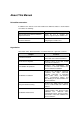
About This Manual Related Documentation In addition to this manual, each H3C S7500 Series Ethernet Switches documentation set includes the following: Manual Description H3C S7500 Series Ethernet Switches Operation Manual Guides the user to configure the features supported by the S7500 series. H3C S7500 Series Ethernet Switches Command Manual Elaborates on the commands configuring the S7500 series.
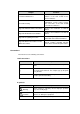
Chapter Contents 7 Software Maintenance Introduces how to load and upgrade the software of the H3C S7500 Series Ethernet Switches. 8 Troubleshooting Introduces how to troubleshoot the configuration system, power system, fans, and LPUs of the H3C S7500 Series Ethernet Switches. Appendix A B68-22 Cabinet Installation Introduces the installation of a B68-22 cabinet. Appendix B N68 Cabinet Installation Introduces the installation of an N68-22 cabinet.
Environmental Protection This product has been designed to comply with the requirements on environmental protection. For the proper storage, use and disposal of this product, national laws and regulations must be observed.
Installation Manual H3C S7500 Series Ethernet Switches Table of Contents Table of Contents Chapter 1 Product Overview ........................................................................................................ 1-1 1.1 Introduction ........................................................................................................................ 1-1 1.1.1 Introduction to S7500 Series Ethernet Switches..................................................... 1-1 1.1.
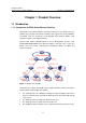
Installation Manual H3C S7500 Series Ethernet Switches Chapter 1 Product Overview Chapter 1 Product Overview 1.1 Introduction 1.1.1 Introduction to S7500 Series Ethernet Switches H3C S7500 Series Ethernet Switches (hereinafter referred to as the S7500 series) are modular, large-capacity L2/L3 Ethernet switches that support wire-speed forwarding. The S7500 series are designed for IP metropolitan area networks (MANs), large enterprise networks, and campus networks.
Installation Manual H3C S7500 Series Ethernet Switches Chapter 1 Product Overview Note: z Refer to H3C S7502 Ethernet Switch Installation Manual for detailed information about the S7502. z In the later chapters, only the S7503, S7506, and S7506R are involved. 1.1.
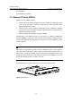
Installation Manual H3C S7500 Series Ethernet Switches Chapter 1 Product Overview [2]: Extendable. [3]: Extendable up to 256 K. 1.3 Salience III Series SRPUs Salience III series SRPUs include: z Salience III: If load sharing is implemented on the S7506R, the switching capacity can be up to 384 Gbps. It provides an XG high speed bus, supporting LPUs applying an XG high speed bus. z Salience III Plus: If load sharing is implemented on the S7506R, the switching capacity can be up to 768 Gbps.
Installation Manual H3C S7500 Series Ethernet Switches Chapter 1 Product Overview Figure 1-3 Salience III Plus Figure 1-4 Salience III Edge 1.3.
Installation Manual H3C S7500 Series Ethernet Switches Chapter 1 Product Overview Salience III (LS81SRPG) Item Dimensions (H x W x D) Salience III Edge (LS81SRPG3) 45.1 × 376.7 × 354.5 mm (1.8 × 14.8 × 14 in.
Installation Manual H3C S7500 Series Ethernet Switches Chapter 1 Product Overview (1) (22) (21) (2) (3) (4) (5) (6) (7) (8) (9) (10) (11) (19) (18) (17) (16) (15) (14) (13) (12) (20) (1) SFP port number (3) Console port (5) LINK LED of the management Ethernet port (7) RUN LED of LPU (9) RUN LED of SRPU (11) Silkscreen (13) SRPU edge (pink) (15) Ejector lever (17) FAIL LED of the power (19) FAIL LED of the fan (21) CF card port (2) SFP port (Gigabit) (4) Management Ethernet port (6) ACT LED of the
Installation Manual H3C S7500 Series Ethernet Switches Chapter 1 Product Overview Note: z Do not remove the CF card when it is performing a read or write operation. z Do not disconnect the power supply when the CF card is performing a read or write operation. z Execute the umount command in user view before removing the CF card. II.
Installation Manual H3C S7500 Series Ethernet Switches Chapter 1 Product Overview Item Description Used for the switch’s software upgrade and network management Function and service The following table describes the port status LEDs. Table 1-5 10Base-T/100Base-TX port LED state description LED State Description OFF No link is present. ON A link is present. OFF No data is being transmitted or received. Blinking Data is being transmitted or received.
Installation Manual H3C S7500 Series Ethernet Switches Chapter 1 Product Overview Central wavelength SFP module Connector Matching cable SFP-GE-LH40 -SM1550 SFP-GE-LH70 -SM1550 Maximum transmission distance 40 km (about 25 mi) 1,550 nm LC 9 µm/125 µm single-mode optical fiber SFP-GE-LH10 0-SM1550 70 km (43 mi) 100 km (62 mi) SFP-GE-LH70 -SM1470-CW 1,470 nm LC 9 µm/125 µm single-mode optical fiber 70 km (43 mi) SFP-GE-LH70 -SM1490-CW 1,490 nm LC 9 µm/125 µm single-mode optical fiber 70
Installation Manual H3C S7500 Series Ethernet Switches Chapter 1 Product Overview 1.3.5 System Status LEDs Note: When two SRPUs are configured on an S7506R Ethernet switch, all the other LEDs on the standby SRPU are constantly OFF except the LEDs of the SRPG. I. Board LEDs SRPG: The LEDs of the SRPG show the status of the SRPU. LPU1, LPU2, LPU3 (LPU4, LPU5, LPU6): The LEDs of these LPUs respectively show the status of three LPUs (for the S7503), or six LPUs (for the S7506 or S7506R).
Installation Manual H3C S7500 Series Ethernet Switches Chapter 1 Product Overview Note: If the FAIL LED on the S7503 is on, it is also possible that the power module is in position but the power switch is not turned on. III. Fan tray LEDs (FAN) FAN: The LEDs of the fan tray show the status of the fan tray. Table 1-10 Description of fan tray LEDs LED State description ON: The fan tray operates normally. OK (Green) OFF: The fan tray is faulty or the fan tray is not in position.
Installation Manual H3C S7500 Series Ethernet Switches Chapter 1 Product Overview 1.4.
Installation Manual H3C S7500 Series Ethernet Switches Chapter 1 Product Overview XGbus is silkscreened on the S7500 series chassis (hereinafter referred to as the S7500 XGbus). The backplane of the S7500 series supports XG high speed bus, and thus can provide even higher switching capacity. Depending on the input power, the chassis of the S7500 series can be divided into AC chassis and DC chassis.
Installation Manual H3C S7500 Series Ethernet Switches Chapter 1 Product Overview (1) Grounding screw (3) Bail latch (5) COM port (PSE monitoring port) (7) NEG (-) terminal of the PoE power input (9) Air filter (2) Power switch of power distribution box (4) Socket of AC power distribution box (6) RTN (+) terminal of the PoE power input: (8) Handle on the rear panel Figure 1-7 Rear view of the S7503 chassis (S7503-AC-XG-PoE chassis in the example) Caution: z The handle on the rear panel is used for rem
Installation Manual H3C S7500 Series Ethernet Switches z Chapter 1 Product Overview The power distribution area is at the chassis bottom near to the rear panel. There is an AC power distribution box for AC power input or a DC power distribution box for DC power input. z There are a –48 VDC power input terminal and a COM port (PoE management Ethernet port) on the back of the PoE-capable S7503 XGbus chassis. II. S7506 Figure 1-8 shows the chassis and slots of the S7506.
Installation Manual H3C S7500 Series Ethernet Switches Chapter 1 Product Overview (1) Grounding screw (3) Bail latch (5) COM port (PSE monitoring port) (7) NEG (-) terminal of PoE power input (9) Air filter (2) Power switch (4) Power socket (6) RTN (+) terminal of PoE power input (8) Handle on the rear panel Figure 1-9 Rear view of the S7506 chassis (S7506-AC-XG-PoE chassis in the example) Each area is hot-swappable. z The board area contains seven horizontal slots.
Installation Manual H3C S7500 Series Ethernet Switches Chapter 1 Product Overview SRPUs 主控板 风扇框 Fan tray 业务板 LPUs Power m odule 电源模块 机箱拉手 Chass is handle Figure 1-10 Chassis of the S7506R The rear panel of the chassis of the S7506R is similar to that of the S7506. For the layout, see Figure 1-9. Each area is hot-swappable. z In the board area, there are eight horizontal slots. The topmost two slots are for required SRPUs. The S7506R provides SRPU redundancy backup.
Installation Manual H3C S7500 Series Ethernet Switches Chapter 1 Product Overview Note: For the S7500 series, a board with pink edges can be inserted only into a slot indicated by a pink area on the fan tray, and a board with purple or green edges can be inserted only into a slot indicated by a purple area. 1.5.3 Backplane The backplane of the S7500 series is located in the integrated chassis and implements high-speed data exchange and management & control signal exchange between SRPUs and LPUs.
Installation Manual H3C S7500 Series Ethernet Switches Chapter 1 Product Overview 1.5.4 Power Supply Note: z The S7500 series support AC and DC power supply. You can select AC or DC power modules as required. z Only one power module can ensure the normal operation of the S7503. However, the S7503 provides two power module slots to implement 1+1 redundancy backup. z Two power modules can ensure the normal operation of the S7506 or the S7506R.
Installation Manual H3C S7500 Series Ethernet Switches Chapter 1 Product Overview Figure 1-13 Power distribution box (dual-input dual-switch AC power distribution box in the example) (1) (2) (3) (4) (5) (1) Screw holes (3) Bail latch (5) Power socket (2) Power switch (4) Grounding screw Figure 1-14 Rear view of power distribution box (dual-input dual-switch AC power distribution box in the example) I.
Installation Manual H3C S7500 Series Ethernet Switches Chapter 1 Product Overview two DC power modules are equipped but only one input is connected, the SRPU displays alarm information for the unsupplied module. The AC power distribution box of the S7503 supports two power inputs, each of z which has a separate power switch. One input can only maintain the normal operation of the corresponding AC power module.
Installation Manual H3C S7500 Series Ethernet Switches Chapter 1 Product Overview III. DC power module For DC power supply, you should use DC power modules and DC power distribution boxes. Table 1-15 Specifications for DC power module Item Specification Rated voltage range –48 VDC to –60 VDC Input voltage range –36 VDC to –72 VDC Maximum output power 450 W 1.5.5 PoE Power Supply The S7500 series support power-over-Ethernet (PoE).
Installation Manual H3C S7500 Series Ethernet Switches Chapter 1 Product Overview Note: z The S7500 series support a maximum PoE input power of 2400 W. z If the PSE2500-A3 is used, one rectifier can supply 1250 W, two 2400 W, and three in 2+1 redundancy mode also 2400 W at an input voltage of 100 to 140 VAC. One rectifier can supply 2500 W at a voltage of 200 to 240 VAC and two power modules are required for redundancy backup.
Installation Manual H3C S7500 Series Ethernet Switches Chapter 1 Product Overview (1) Fan (3) LPU slot number (0 to 6) (2) Lock Figure 1-17 Fan tray of the S7506 (1) (3) (2) (1) Captive screw (3) Fan (2) LPU slot number (0 to 7) Figure 1-18 Fan tray of the S7506R The fan trays of the S7503 and S7506R are different from that of the S7506 in design. z The fan trays of the S7503 and S7506R are fixed by screws. z The fan tray of the S7506 is fixed by two locks.
Installation Manual H3C S7500 Series Ethernet Switches Chapter 1 Product Overview 1) Simutaneously pull the two locks outward to release them. 2) Gently pull the fan tray out. 1.6 Technical Specifications for the S7500 Series Table 1-16 Technical specifications for the S7500 series Item S7503 S7506 S7506R Physical dimensions (H × W × D) 352.8 × 436 × 480 mm (13.9 x 17.2 x 18.9 in.) 486.2 × 436 × 480 mm (19.1 x 17.2 x 18.9 in.) 530.6 × 436 × 480 mm (20.9 x 17.2 x 18.9 in.
Installation Manual H3C S7500 Series Ethernet Switches Chapter 1 Product Overview 1.
Installation Manual H3C S7500 Series Ethernet Switches Table of Contents Table of Contents Chapter 2 Line Processing Units ................................................................................................. 2-1 2.1 Introduction to LPUs .......................................................................................................... 2-1 2.2 LS81FT48E........................................................................................................................ 2-1 2.2.
Installation Manual H3C S7500 Series Ethernet Switches Table of Contents 2.11 LS81T12P ...................................................................................................................... 2-21 2.11.1 Technical Specifications...................................................................................... 2-21 2.11.2 Panel and LEDs .................................................................................................. 2-22 2.11.3 Matching Cable ............................
Installation Manual H3C S7500 Series Ethernet Switches Table of Contents 2.21.2 Panel and LEDs .................................................................................................. 2-46 2.21.3 Matching Cable ................................................................................................... 2-47 2.22 LS81TGX2 ..................................................................................................................... 2-47 2.22.1 Technical Specifications................
Installation Manual H3C S7500 Series Ethernet Switches Chapter 2 Line Processing Units Chapter 2 Line Processing Units 2.1 Introduction to LPUs The modular design of the S700 series provides a reasonable system architecture as well as standard, mutually independent function modules. Currently, the S7500 series provide autosensing 10/100/1000 Mbps Ethernet electrical ports, 100 Mbps Ethernet (single mode/multi-mode) optical ports, GBIC/SFP (single mode/multi-mode) optical ports, and 10GE optical ports.
Installation Manual H3C S7500 Series Ethernet Switches Chapter 2 Line Processing Units Item Matching cable and transmission distance Specification maximum Category-5 twisted pair with a maximum transmission distance of 100 m (328.1 ft) IEEE 802.3 IEEE 802.3u IEEE 802.3ad IEEE 802.3x IEEE 802.1p Compliant standards IEEE 802.1D IEEE 802.1Q IEEE 802.1X IEEE 802.1s IEEE 802.1w 2.2.
Installation Manual H3C S7500 Series Ethernet Switches Chapter 2 Line Processing Units Table 2-2 LED description of the LS81FT48E LED LINK/ACT Status Meaning OFF No link is present. ON A link is present. Blinking Data is being transmitted/received. 2.2.3 Matching Cable The 10/100Base-TX Ethernet ports use category-5 twisted pairs and RJ-45 connectors, with a maximum transmission distance of 100 m (328.1 ft). 2.3 LS81FT48F Figure 2-4 LS81FT48F appearance 2.3.
Installation Manual H3C S7500 Series Ethernet Switches Chapter 2 Line Processing Units Item Specification z Port speed Matching cable and transmission distance z maximum 10/100 Mbps half-duplex/full-duplex MDI/MDI-X autosensing Category-5 twisted pair, with a maximum transmission distance of 100 m (328.1 ft) Maximum PoE distance 100 m (328.1 ft) Maximum power each port can provide 15.4 W IEEE 802.3 IEEE 802.3u IEEE 802.3x IEEE 802.3ad IEEE 802.1p IEEE 802.1D Compliant standard IEEE 802.
Installation Manual H3C S7500 Series Ethernet Switches Chapter 2 Line Processing Units (1) Silkscreen of the LPU name (3) LPU edge (purple) (5) 10/100Base-TX Ethernet port status LED (2) Captive screw (4) Ejector lever (6) 10/100Base-TX Ethernet port (supporting PoE) Figure 2-6 Partially amplified view of the LS81FT48F panel Each 10/100Base-TX Ethernet port has a green LED. Table 2-4 LED description of the LS81FT48F LED LINK/ACT Status Meaning OFF No link is present. ON A link is present.
Installation Manual H3C S7500 Series Ethernet Switches Chapter 2 Line Processing Units 2.4.1 Technical Specifications The LS81FP48 provides forty-eight 100Base-FX-SFP ports operating in the full-duplex mode. Table 2-5 LS81FP48 specifications Item Specification CPU MPC8241, 200 MHz Boot ROM 512 KB SDRAM 128 MB Dimensions (H x W x D) 40.1 × 376.7 × 354.5 mm (1.6 × 14.8 × 14 in.
Installation Manual H3C S7500 Series Ethernet Switches Chapter 2 Line Processing Units (1) Silkscreen of the LPU name (3) LPU edge (purple) (5) 100Base-FX-SFP port status LED (2) Captive screw (4) Ejector lever (6) 100Base-FX-SFP port Figure 2-9 Partially amplified view of the LS81FP48 panel Each 100Base-FX-SFP port has a green LED. Table 2-6 LED description of the LS81FP48 LED LINK/ACT Status Meaning OFF No link is present. ON A link is present. Blinking Data is being transmitted/received. 2.
Installation Manual H3C S7500 Series Ethernet Switches Chapter 2 Line Processing Units Central wavelength SFP module SFP-FE-LH40-SM 1310 1,310 nm SFP-FE-LH80-SM 1550 1,550 nm SFP-FE-LX-SM13 10-BIDI 1,550 nm (receive)/131 0 nm (transmit) SFP-FE-LX-SM15 50-BIDI 1310 (transmit)/15 50 (receive) Matching cable Maximum transmission distance LC 9 µm/125 µm single mode optical fiber cable 40 km (24.9 mi) LC 9 µm/125 µm single mode optical fiber cable 80 km (49.
Installation Manual H3C S7500 Series Ethernet Switches Chapter 2 Line Processing Units Item Specification Connector RJ-45 Number of ports 8 z Port speed z Matching cable and transmission distance maximum Mbps Category-5 twisted pair, with a maximum transmission distance of 100 m (328.1 ft) z z z z Compliant standard 10/100/1000 half-duplex/full-duplex MDI/MDI-X autosensing z z z z z IEEE 802.3 IEEE 802.3u IEEE 802.3ab IEEE 802.3x IEEE 802.1D IEEE 802.1Q IEEE 802.1X IEEE 802.1s IEEE 802.
Installation Manual H3C S7500 Series Ethernet Switches Chapter 2 Line Processing Units (2) 10/100/1000Base-T Ethernet port status LED (LINK) (1) Ethernet port number (3) 10/100/1000Base-T Ethernet port status LED (ACT) (5) Captive screw (7) Ejector lever (4) Silkscreen of the LPU name (6) LPU edge (purple) (8) 10/100/1000Base-T Ethernet port (Gigabit) Figure 2-12 Partially amplified view of the LS81GT8UE panel Each 10/100/1000Base-T Ethernet port has two LEDs.
Installation Manual H3C S7500 Series Ethernet Switches Chapter 2 Line Processing Units 2.6 LS82GT20 Figure 2-13 LS82GT20 appearance 2.6.1 Technical Specifications The LS82GT20 provides twenty autosensing 10/100/1000Base-T Ethernet ports. Table 2-10 LS82GT20 specifications Item Specification CPU MPC8241, 200 MHz Boot ROM 512 KB SDRAM 64 MB Dimensions (H x W x D) 40.1 × 376.7 × 354.5 mm (1.6 × 14.8 × 14 in.
Installation Manual H3C S7500 Series Ethernet Switches Chapter 2 Line Processing Units 2.6.2 Panel and LEDs Figure 2-14 LS82GT20 panel (1) Silkscreen of the LPU name (3) LPU edge (purple) (5) 10/100/1000Base-T Ethernet port (2) Captive screw (4) Ejector lever (6) 10/100/1000Base-T Ethernet port status LED Figure 2-15 Partially amplified view of the LS82GT20 panel Each 10/100/1000Base-T Ethernet port has a LED.
Installation Manual H3C S7500 Series Ethernet Switches Chapter 2 Line Processing Units 2.7 LS82GT20A Figure 2-16 LS82GT20A appearance 2.7.1 Technical Specifications The LS82GT20A provides twenty autosensing 10/100/1000Base-T Ethernet ports. Table 2-12 LS82GT20A specifications Item Specification CPU MPC8241, 200 MHz Boot ROM 512 KB SDRAM 128 MB Dimensions (W x D) 40.1 × 376.7 × 354.5 mm (1.6 × 14.8 × 14 in.
Installation Manual H3C S7500 Series Ethernet Switches Chapter 2 Line Processing Units 2.7.2 Panel and LEDs Figure 2-17 LS82GT20A panel (1) 10/100/1000Base-T Ethernet port (3) Captive screw (5) Ejector lever (2) Silkscreen of the LPU name (4) LPU edge (purple) (6) Ethernet port status LED Figure 2-18 Partially amplified view of the LS82GT20A panel Each 10/100/1000Base-T Ethernet port has a LED. Table 2-13 LED description of the LS82GT20A LED LINK/ACT Status Meaning OFF No link is present.
Installation Manual H3C S7500 Series Ethernet Switches Chapter 2 Line Processing Units 2.8 LS81GT48 Figure 2-19 LS81GT48 appearance 2.8.1 Technical Specifications The LS81GT48 provides forty-eight autosensing 10/100/1000Base-T Ethernet ports. Table 2-14 LS81GT48 specifications Item Specification CPU MPC8241, 200 MHz Boot ROM 512 KB SDRAM 128 MB Dimensions (H x W x D) 40.1 × 376.7 × 354.5 mm (1.6 × 14.8 × 14 in.
Installation Manual H3C S7500 Series Ethernet Switches Chapter 2 Line Processing Units 2.8.2 Panel and LEDs Figure 2-20 LS81GT48 panel (1) Silkscreen of the LPU name (3) LPU edge (purple) (5) 10/100/1000Base-T Ethernet port status LED (2) Captive screw (4) Ejector lever (6) 10/100/1000Base-T Ethernet port Figure 2-21 Partially amplified view of the LS81GT48 panel Each 10/100/1000Base-T Ethernet port has a green LED.
Installation Manual H3C S7500 Series Ethernet Switches Chapter 2 Line Processing Units 2.9 LS81GT48A Figure 2-22 LS81GT48A appearance 2.9.1 Technical Specifications The LS81GT48A provides forty-eight autosensing 10/100/1000Base-T Ethernet ports. All the ports support PoE, that is, they supply power to remote PDs through Ethernet twisted pair cables. Table 2-16 LS81GT48A specifications Item Specification CPU MPC8241, 200 MHz Boot ROM 512 KB SDRAM 128 MB Dimensions (H x W x D) 40.1 × 376.7 × 354.
Installation Manual H3C S7500 Series Ethernet Switches Chapter 2 Line Processing Units Item Specification z z z z z Compliant standard z z z z z z IEEE 802.3 IEEE 802.3u IEEE 802.3ab IEEE 802.3x IEEE 802.1p IEEE 802.1D IEEE 802.1Q IEEE 802.1X IEEE 802.1s IEEE 802.1w IEEE 802.3af 2.9.
Installation Manual H3C S7500 Series Ethernet Switches Chapter 2 Line Processing Units Table 2-17 LED description of the LS81GT48A LED LINK/ACT Status Meaning OFF No link is present. ON A link is present. Blinking Data is being transmitted/received. 2.9.3 Matching Cable The 10/100/1000Base-T Ethernet ports use category-5 twisted pairs and RJ-45 connectors, with a maximum transmission distance of 100 m (328.1 ft). 2.10 LS81GT48B Figure 2-25 LS81GT48B appearance 2.10.
Installation Manual H3C S7500 Series Ethernet Switches Chapter 2 Line Processing Units Item Specification z z Port speed z z Matching cable and transmission distance maximum Category-5 twisted pair, with a maximum transmission distance of 100 m (328.1 ft) z z z z z Compliant standard 10 Mbps half-duplex/full-duplex 100 Mbps half-duplex/full-duplex 1000 Mbps half-duplex/full-duplex MDI/MDI-X autosensing z z z z z IEEE 802.3 IEEE 802.3u IEEE 802.3ab IEEE 802.3x IEEE 802.1p IEEE 802.1D IEEE 802.
Installation Manual H3C S7500 Series Ethernet Switches Chapter 2 Line Processing Units (1) Silkscreen of the LPU name (3) LPU edge (purple) (5) 10/100/1000Base-T Ethernet port status LED (2) Captive screw (4) Ejector lever (6) 10/100/1000Base-T Ethernet port Figure 2-27 Partially amplified view of the LS81GT48B panel Each 10/100/1000Base-T Ethernet port has a green LED. Table 2-19 LED description of the LS81GT48B LED LINK/ACT Status Meaning OFF No link is present. ON A link is present.
Installation Manual H3C S7500 Series Ethernet Switches Chapter 2 Line Processing Units Table 2-20 LS81T12P specifications Item Specification CPU MPC8241, 200 MHz Boot ROM 512 KB SDRAM 128 MB Dimensions (H x W x D) 40.1 × 376.7 × 354.5 mm (1.6 × 14.8 × 14 in.
Installation Manual H3C S7500 Series Ethernet Switches Chapter 2 Line Processing Units (1) Port number (3) Captive screw (5) Ejector lever (7) 10/100/1000Base-T Ethernet port status LED (2) Silkscreen of the LPU name (4) LPU edge (purple) (6) 1000Base-X-SPF port (8) 10/100/1000Base-T Ethernet port Figure 2-30 Partially amplified view of the LS81T12P panel The following table describes the LED. Table 2-21 LED description of the LS81T12P LED LINK/ACT Status Meaning OFF No link is present.
Installation Manual H3C S7500 Series Ethernet Switches SFP module Chapter 2 Line Processing Units Central wavelength Connector SFP-GE-LX-SM131 0-A 1,310 nm LC SFP-GE-LH40-SM1 310 SFP-GE-LH40-SM1 550 SFP-GE-LH70-SM1 550 1,550 nm LC SFP-GE-LH100-SM 1550 SFP-GE-LH70-SM1 470-CW SFP-GE-LH70-SM1 490-CW SFP-GE-LH70-SM1 510-CW SFP-GE-LH70-SM1 530-CW SFP-GE-LH70-SM1 550-CW SFP-GE-LH70-SM1 570-CW SFP-GE-LH70-SM1 590-CW SFP-GE-LH70-SM1 610-CW 1,470 nm 1,490 nm 1,510 nm 1,530 nm 1,550 nm 1,570 nm
Installation Manual H3C S7500 Series Ethernet Switches Chapter 2 Line Processing Units II. Cables for the twelve 10/100/1000Base-T Ethernet ports The 10/100/1000Base-T Ethernet ports use category-5 twisted pairs and RJ-45 connectors, with a maximum transmission distance of 100 m (328.1 ft). 2.12 LS81T12PE Figure 2-31 LS81T12PE appearance 2.12.1 Technical Specifications The LS81T12PE can serve as the SRPU of the S7502.
Installation Manual H3C S7500 Series Ethernet Switches Chapter 2 Line Processing Units Item Specification z z z z z z Compliant standard z z z z z z IEEE 802.3 IEEE 802.3u IEEE 802.3z IEEE 802.3ab IEEE 802.1p IEEE 802.1Q IEEE 802.1D IEEE 802.1X IEEE 802.1s IEEE 802.1w IEEE 802.3x IEEE 802.3ad 2.12.2 Panel and LEDs LS81T12PE provides twelve 10/100/1000BASE-T ports and four 1000BASE-X-SFP ports, and each port has a status LED.
Installation Manual H3C S7500 Series Ethernet Switches Chapter 2 Line Processing Units Table 2-24 LED description of the LS81T12PE LED LINK/ACT Status Meaning OFF No link is present. ON A link is present. Blinking Data is being transmitted/received. 2.12.3 Matching Cable Refer to section 2.11 “LS81T12P“ on page 2-21. 2.13 LS81P12T Figure 2-34 LS81P12T appearance 2.13.
Installation Manual H3C S7500 Series Ethernet Switches Chapter 2 Line Processing Units Item Matching cable and transmission distance Specification maximum Category-5 twisted pair, with a maximum transmission distance of 100 m (328.1 ft) z z z z z z Compliant standard z z z z z z IEEE 802.3 IEEE 802.3u IEEE 802.3z IEEE 802.3ab IEEE 802.1p IEEE 802.1Q IEEE 802.1D IEEE 802.1X IEEE 802.1s IEEE 802.1w IEEE 802.3x IEEE 802.3ad 2.13.
Installation Manual H3C S7500 Series Ethernet Switches Chapter 2 Line Processing Units Table 2-26 LED description of the LS81P12T LED Status LINK/ACT Meaning OFF No link is present. ON A link is present. Blinking Data is being transmitted/received. 2.13.3 Matching Cable Refer to section 2.11.3 “Matching Cable” on page 2-23. 2.14 LS81P12TE Figure 2-37 LS81P12TE appearance 2.14.1 Technical Specifications The LS81P12TE can serve as the SRPU of the S7502.
Installation Manual H3C S7500 Series Ethernet Switches Chapter 2 Line Processing Units Item Specification SFP modules Refer to Table 2-22 Matching cable and maximum transmission distance Category-5 twisted pair cable, with a maximum transmission distance of 100 m (328.1 ft) z z z z z Compliant standard z z z z z z z IEEE 802.3 IEEE 802.3u IEEE 802.3z IEEE 802.3ab IEEE 802.1p IEEE 802.1Q IEEE 802.1D IEEE 802.1X IEEE 802.1s IEEE 802.1w IEEE 802.3x IEEE 802.3ad 2.14.
Installation Manual H3C S7500 Series Ethernet Switches Chapter 2 Line Processing Units 2.14.3 Matching Cable Refer to section 2.11 “LS81T12P” on page 2-21. 2.15 LS81T16P Figure 2-40 LS81T16P appearance 2.15.1 Technical Specifications The LS81T16P adopts an XG high-speed bus. It can also serve as the SRPU of the S7502. Table 2-28 LS81T16P specifications Item Specification CPU MPC8245, 300M BOOT ROM 512 KB Flash memory 32 MB SDRAM 256 MB Dimensions (W x D) 366.7 x 340 mm (14.4 x 13.4 in.
Installation Manual H3C S7500 Series Ethernet Switches Chapter 2 Line Processing Units Item Specification z z z z z z Compliant standard z z z z z z IEEE 802.3 IEEE 802.3u IEEE 802.3z IEEE 802.3ab IEEE 802.1p IEEE 802.1Q IEEE 802.1D IEEE 802.1X IEEE 802.1s IEEE 802.1w IEEE 802.3x IEEE 802.3ad Note: When using the LS81T16P as an LPU of the S7503/S7506/S7506R, you can only use it together with a Salience III or Salience III Plus SRPU.
Installation Manual H3C S7500 Series Ethernet Switches Chapter 2 Line Processing Units (1) Silkscreen of the LPU name (3) LPU edge (green) (5) 1000Base-X-SPF port (7) 10/100/1000Base-T Ethernet port (2) Captive screw (4) Ejector lever (6) 1000Base-X-SFP port status LED Figure 2-42 Partially amplified view of the LS81T16P panel The following table describes the LED of the LS81T16P: Table 2-29 LED description of the LS81T16P LED LINK/ACT Status Meaning OFF No link is present. ON A link is present.
Installation Manual H3C S7500 Series Ethernet Switches Chapter 2 Line Processing Units Table 2-30 LS81T32P specifications Item Specification CPU MPC8245, 300 MHz BOOT ROM 512 KB Flash memory 32 MB SDRAM 256 MB Dimensions (H x W x D) 40.1 × 376.7 × 354.5 mm (1.6 × 14.8 × 14 in.
Installation Manual H3C S7500 Series Ethernet Switches Chapter 2 Line Processing Units Note: When using the LS81T32P as an LPU of the S7503/S7506/S7506R switch, you can only use it together with a Salience III or Salience III Plus SRPU. z If you use the LS81T32P together with a Salience III Plus SRPU, you can insert it into any LPU slot on the S7503/S7506/S7506R.
Installation Manual H3C S7500 Series Ethernet Switches Chapter 2 Line Processing Units Table 2-31 LED state description of LS81T32P LED Status LINK/ACT Meaning OFF No link is present. ON A link is present. Blinking Data is being transmitted/received. 2.16.3 Matching Cable Refer to section 2.11 “LS81T12P” on page 2-21. 2.17 LS81GP8UB Figure 2-46 LS81GP8UB appearance 2.17.1 Technical Specifications The LS81GP8UB provides eight 1000Base-X-SFP ports operating in the full-duplex mode.
Installation Manual H3C S7500 Series Ethernet Switches Chapter 2 Line Processing Units Item Specification z z z z Compliant standard z z z z z z IEEE 802.3 IEEE 802.3z IEEE 802.1p IEEE 802.1Q IEEE 802.1D IEEE 802.3x IEEE 802.3ad IEEE 802.1X IEEE 802.1s IEEE 802.1w Note: z The LS81GP8UB can only be used together with a Salience III and Salience III Edge SRPU.
Installation Manual H3C S7500 Series Ethernet Switches Chapter 2 Line Processing Units (1) Port number (3) Captive screw (5) Ejector lever (7) 1000Base-X-SFP port (2) Silkscreen of the LPU name (4) LPU edge (purple) (6) 1000Base-X-SFP port status LED Figure 2-48 Partially amplified view of the LS81GP8UB panel The following table describes the LED of the LS81GP8UB. Table 2-33 LED description of the LS81GP8UB LED LINK/ACT Status Meaning OFF No link is present. ON A link is present.
Installation Manual H3C S7500 Series Ethernet Switches Chapter 2 Line Processing Units Table 2-34 LS82GP20 specifications Item Specification CPU MPC8241, 200 MHz Boot ROM 512 KB SDRAM 64 MB Dimensions (H x W x D) 40.1 × 376.7 × 354.5 mm (1.6 × 14.8 × 14 in.) Maximum power consumption 35 W Connector LC Number of ports 20 Port speed 1000 Mbps full-duplex SFP modules Refer to Table 2-22 z z z z z Compliant standard z z z z z 2.18.
Installation Manual H3C S7500 Series Ethernet Switches Chapter 2 Line Processing Units (1) Port number (3) Captive screw (5) Ejector lever (7) 1000Base-X-SFP port status LED (2) Silkscreen of the LPU name (4) LPU edge (purple) (6) 1000Base-X-SFP port Figure 2-51 Partially amplified view of the LS82GP20 panel The following table describes the LED of the LS82GP20. Table 2-35 LED description of the LS82GP20 LED LINK/ACT Status Meaning OFF No link is present. ON A link is present.
Installation Manual H3C S7500 Series Ethernet Switches Chapter 2 Line Processing Units Table 2-36 LS82GP20A specifications Item Specification CPU MPC8241, 200 MHz Boot ROM 512 KB SDRAM 128 MB Dimensions (H x W x D) 40.1 × 376.7 × 354.5 mm (1.6 × 14.8 × 14 in.) Maximum power consumption 35 W Connector LC Number of ports 20 Port speed 1000 Mbps full-duplex SFP modules Refer to Table 2-22 z z z z z Compliant standard z z z z z 2.19.
Installation Manual H3C S7500 Series Ethernet Switches Chapter 2 Line Processing Units (1) Port number (3) Captive screw (5) Ejector lever (7) 1000Base-X-SFP port status LED (2) Silkscreen of the LPU name (4) LPU edge (purple) (6) 1000Base-X-SFP port Figure 2-54 Partially amplified view of the LS82GP20A panel The following table describes the LED of the LS82GP20A. Table 2-37 LED description of the LS82GP20A LED LINK/ACT Status Meaning OFF No link is present. ON A link is present.
Installation Manual H3C S7500 Series Ethernet Switches Chapter 2 Line Processing Units 2.20.1 Technical Specifications The LS81GP48 adopts an XG high-speed bus and provides forty-eight 1000Base-X-SFP ports operating in the full-duplex mode. It can also serve as the SRPU of the S7502. Table 2-38 LS81GP48 specifications Item Specification CPU MPC8245, 300 MHz BOOT ROM 512 KB Flash memory 32 MB SDRAM 256 MB Dimensions (H x W x D) 40.1 × 376.7 × 354.5 mm (1.6 × 14.8 × 14 in.
Installation Manual H3C S7500 Series Ethernet Switches Chapter 2 Line Processing Units 2.20.2 Panel and LEDs Figure 2-56 LS81GP48 panel (1) Silkscreen of the LPU name (3) LPU edge (green) (5) 1000Base-X-SFP port status LED (2) Captive screw (4) Ejector lever (6) 1000Base-X-SFP port Figure 2-57 Partially amplified view of the LS81GP48 panel The following table describes the LED of the LS81GP48: Table 2-39 LED description of the LS81GP48 LED LINK/ACT Status Meaning OFF No link is present.
Installation Manual H3C S7500 Series Ethernet Switches Chapter 2 Line Processing Units 2.21 LS81TGX1C Figure 2-58 LS81TGX1C appearance 2.21.1 Technical Specifications The LS81TGX1C provides one 10GBase-R-XENPAK port operating the full-duplex mode. Table 2-40 LS81TGX1C specifications Item Specification CPU MPC8245, 300 MHz Boot ROM 512 KB SDRAM 64 MB Dimensions (H x W x D) 40.1 × 376.7 × 354.5 mm (1.6 × 14.8 × 14 in.
Installation Manual H3C S7500 Series Ethernet Switches Chapter 2 Line Processing Units 2.21.2 Panel and LEDs Figure 2-59 LS81TGX1C panel (1) 10GBase-R-XENPAK port status LED (LINK) (3) Silkscreen of the LPU (5) LPU edge (green) (7) 10GBase-R-XENPAK port (2) 10GBase-R-XENPAK port status LED (ACT) (4) Captive screw (6) Ejector lever (8) Captive screw Figure 2-60 Partially amplified view of the LS81TGX1C panel The following table describes the LEDs of the LS81TGX1C.
Installation Manual H3C S7500 Series Ethernet Switches Chapter 2 Line Processing Units 2.21.3 Matching Cable Table 2-42 Cables for the LS81TGX1C XENPAK module Central wavelen gth XENPAK-SX-MM850 850 nm XENPAK-LX-SM1310 1310 nm XENPAK-LH40-SM1550 1550 nm Connect or Matching cable Multimode fiber SC 9µm/125µm single mode fiber Maximum transmission distance 300 m (984 ft) 10 km (6 mi) 40 km (25 mi) 2.22 LS81TGX2 Figure 2-61 LS81TGX2 appearance 2.22.
Installation Manual H3C S7500 Series Ethernet Switches Chapter 2 Line Processing Units Item Specification z z XFP modules z z z z z z z Compliant standard z z z z z XFP-SX-MM850 (850 nm multi-mode fiber with a maximum transmission distance of 300 m [984.3 ft]). XFP-LX-SM1310 (1,310 nm single-mode fiber with a maximum transmission distance of 10 km [6.2 mi]) XFP-LH40-SM1550 (1,550 nm single-mode fiber with a maximum transmission distance of 40 km [24.
Installation Manual H3C S7500 Series Ethernet Switches Chapter 2 Line Processing Units (1) 10GBase-XFP port number (3) 10GBase-XFP port status LED (ACT) (5) Captive screw (7) Ejector lever (2) 10GBase-XFP port status LED (LINK) (4) Silkscreen of the LPU name (6) LPU edge (green) (8) 10GBase-XFP port Figure 2-63 Partially amplified view of the LS81TGX2 panel The following table describes the LEDs of the LS81TGX2: Table 2-44 LED description of the LS81TGX2 LED State OFF No link is present.
Installation Manual H3C S7500 Series Ethernet Switches Chapter 2 Line Processing Units 2.23 LS81TGX4 Figure 2-64 LS81TGX4 appearance 2.23.1 Technical Specifications The LS81TGX4 adopts an XG high-speed bus and provides four 10GBase-XFP ports operating in the full-duplex mode. It can also serve as the SRPU of the S7502. Table 2-46 LS81TGX4 specifications Item Specification CPU MPC8245, 300 MHz BOOT ROM 512 KB Flash memory 32 MB SDRAM 256 MB Dimensions (H x W x D) 40.1 × 376.7 × 354.5 mm (1.
Installation Manual H3C S7500 Series Ethernet Switches Chapter 2 Line Processing Units Item Specification z z z z z Compliant standard z z z z z IEEE 802.3 IEEE 802.3ae IEEE 802.1p IEEE 802.1Q IEEE 802.1D IEEE 802.3x IEEE 802.3ad IEEE 802.1X IEEE 802.1s IEEE 802.1w Note: When using the LS81TGX4 as an LPU of the S7503/S7506/S7506R, you can only use it together with a Salience III or Salience III Plus SRPU.
Installation Manual H3C S7500 Series Ethernet Switches Chapter 2 Line Processing Units (1) 10GBase-XFP port number (3) 10GBase-XFP port status LED (ACT) (5) Captive screw (7) Ejector lever (2) 10GBase-XFP port status LED (LINK) (4) Silkscreen of the LPU name (6) LPU edge (green) (8) 10GBase-XFP port Figure 2-66 Partially amplified view of the LS81TGX4 panel Refer to Table 2-44 in section 2.22.2 "Panel and LEDs" on page 2-48 for the LED description of the LS81TGX4. 2.23.
Installation Manual H3C S7500 Series Ethernet Switches Chapter 2 Line Processing Units Table 2-47 LS81VSNP specifications Item Specification CPU MPC750, 350 MHz BOOT ROM 512 KB SDRAM 256 MB Dimensions (H x W x D) 40.1 × 376.7 × 354.5 mm (1.6 × 14.8 × 14 in.
Installation Manual H3C S7500 Series Ethernet Switches Table of Contents Table of Contents Chapter 3 Installation Preparations............................................................................................. 3-1 3.1 Safety Precautions............................................................................................................. 3-1 3.1.1 General Safety Recommendations ......................................................................... 3-1 3.1.2 Electrical Safety............
Installation Manual H3C S7500 Series Ethernet Switches Chapter 3 Installation Preparations Chapter 3 Installation Preparations 3.1 Safety Precautions To avoid bodily injury and device damage, please read the following safety recommendations carefully before installing the S7500 series. The recommendations do not cover every possible hazardous condition. 3.1.1 General Safety Recommendations z Keep the chassis clean and dust-free. z Keep the chassis and installation tools away from walk areas.
Installation Manual H3C S7500 Series Ethernet Switches Chapter 3 Installation Preparations Caution: Never attempt to lift the chassis by holding the handles on the power modules, or ventilation holes because they were not designed to support the weight of the chassis. Otherwise, device damage or even bodily injury may occur. 3.1.
Installation Manual H3C S7500 Series Ethernet Switches Chapter 3 Installation Preparations 3.1.5 Laser Safety Some LPUs of the S7500 series have optical ports. If such an LPU is operating, do not stare into open optical ports because laser beams emitted from these optical ports will produce high energy, which may hurt your eyes. 3.2 Examining the Installation Site The S7500 series are designed for indoor installation.
Installation Manual H3C S7500 Series Ethernet Switches Chapter 3 Installation Preparations Table 3-2 Limitation on dust content and diameters in the equipment room Mechanical active material Content limit (particles/m³) 4 ≤3 x 10 (No visible dust on desk over three days) Dust particle Note: Dust particle diameter ≥ 5µm Besides, the contents of salt, acid, and sulfide in equipment room shall be strictly restricted. Harmful gases will accelerate the corrosion and aging of metal parts.
Installation Manual H3C S7500 Series Ethernet Switches Chapter 3 Installation Preparations 1) AC power module parameters: z Rated voltage range: 100 to 240 VAC, 50/60Hz z Input voltage range: 90 to 264 VAC, 50/60Hz z Maximum output power: 450 W 2) DC power module parameters: z Rated voltage range: –48 to –60 VDC z Input voltage range: –36 to –72 VDC z Maximum output power: 450 W 3.
Installation Manual H3C S7500 Series Ethernet Switches Chapter 3 Installation Preparations 3.
Installation Manual H3C S7500 Series Ethernet Switches Table of Contents Table of Contents Chapter 4 Hardware Installation .................................................................................................. 4-1 4.1 Confirming Installation Preparations.................................................................................. 4-1 4.2 Installation Flowchart ......................................................................................................... 4-2 4.
Installation Manual H3C S7500 Series Ethernet Switches Chapter 4 Hardware Installation Chapter 4 Hardware Installation Note: The S7500 series are designed for indoor installation. 4.1 Confirming Installation Preparations Before installation, make sure that z You have read Chapter 3 carefully z All requirements mentioned in Chapter 3 “Installation Preparations” are satisfied.
Installation Manual H3C S7500 Series Ethernet Switches Chapter 4 Hardware Installation 4.2 Installation Flowchart Start Mount the switch to the designated position Install modules of the switch Connect the grounding cable Connect the power cable(s) Connect the interface cables Route and bind the cables Check the installation End Figure 4-1 Installation flowchart 4.3 Mounting the Switch to the Designated Position 4.3.
Installation Manual H3C S7500 Series Ethernet Switches Chapter 4 Hardware Installation Figure 4-2 Mount the S7506 in an N68 cabinet I. Installing an N68 cabinet In an N68 cabinet ready for delivery, a place has been arranged for mounting the switch according to the order, and all accessories outside the switch, except for the LPUs and cables, have been installed. For the procedure for installing an N68 cabinet, refer to Appendix B. II.
Installation Manual H3C S7500 Series Ethernet Switches Chapter 4 Hardware Installation 2) Carry the switch with another person to the front of the table. 3) Carry the switch a little higher than the table and put the switch on the table. 4.4 Installing Modules of the Switch Modules of the switch include boards, power modules, power distribution boxes, and fan tray. For detailed installation procedures, see Chapter 7 “Hardware Maintenance”. 4.
Installation Manual H3C S7500 Series Ethernet Switches Chapter 4 Hardware Installation II. Under other grounding environments Note: The following figures mainly illustrate the grounding of the switch through the grounding screw or power input terminal, and never care about the switch model or the positions of the grounding screw and the power input terminal. The following introduces how to ground the switch under different grounding environments.
Installation Manual H3C S7500 Series Ethernet Switches z Chapter 4 Hardware Installation If there is no grounding strip and no grounding body can be buried, the AC-powered Ethernet switch can be grounded through the protection earth (PE) wire of the AC power supply. In this case, make sure that the PE wire of the AC power supply has been well grounded on the side of the power distribution room or AC power transformer.
Installation Manual H3C S7500 Series Ethernet Switches 1) Chapter 4 Hardware Installation Plug one end of the supplied AC power cord into the power socket on the switch and secure the bail latch over the power cord to prevent a falloff. 2) Plug the other end into the socket strip (with lightning protection). Connect the strip to the AC power source in the room. Note: The AC power socket strip with lightning protection is not delivered with the switch and is user-suuplied.
Installation Manual H3C S7500 Series Ethernet Switches Chapter 4 Hardware Installation Figure 4-8 Connect the DC power cables of the S7506 4.6.3 Connecting PoE Power Cables Follow these steps to connect the PoE power cables: 1) Loosen the nuts on the PoE terminal block cover and remove the cover. 2) Loosen the nuts of the PoE terminal block on the rear panel of the switch.
Installation Manual H3C S7500 Series Ethernet Switches Chapter 4 Hardware Installation Figure 4-10 Rear panel of external PoE power supply (PSE2500-A3) 4) Connect the GND OT terminal of the PoE power cable marked with “GND“ to the RTN (+) terminal on the switch and fasten the nut. Connect the other end to the NEG (-) terminal on the panel of external PoE power supply. 5) Connect the PGND OT terminal of the PoE power cable marked with “PGND” to the grounding screw on the switch and fasten the screw.
Installation Manual H3C S7500 Series Ethernet Switches Chapter 4 Hardware Installation Table 4-1 Console cable pinout RJ45 Signal DB-9 Signal 1 RTS 8 CTS 2 DTR 6 DSR 3 TXD 2 RXD 4 SG 5 SG 5 SG 5 SG 6 RXD 3 TXD 7 DSR 4 DTR 8 CTS 7 RTS II. Connection procedure Follow these steps to connect the console cable to configure the switch through a terminal. 1) Connect the DB-9 female connector of the console cable to the serial port on the PC or the configuration terminal.
Installation Manual H3C S7500 Series Ethernet Switches Chapter 4 Hardware Installation II. Connection procedure 1) Connect the RJ-45 connector of the AUX cable to the console port on the switch. 2) Connect the DB-9 connector of the AUX cable to the serial port on the analog Modem. 4.7.3 Connecting the COM Port Cable I. Introduction The COM port cable is an 8-core shielded cable.
Installation Manual H3C S7500 Series Ethernet Switches Chapter 4 Hardware Installation Table 4-2 RJ-45 MDI connector pinouts 10Base-T/100Base-TX 1000Base-T Pinout Signal Function Signal Function 1 Tx+ Transmit data BIDA+ Bi-directional data cable A+ 2 Tx- Transmit data BIDA- Bi-directional data cable A- 3 Rx+ Receive data BIDB+ Bi-directional data cable B+ 4 Reserved — BIDC+ Bi-directional data cable C+ 5 Reserved — BIDC- Bi-directional data cable C- 6 Rx- Receive data BI
Installation Manual H3C S7500 Series Ethernet Switches Chapter 4 Hardware Installation Note: Pinouts 1 and 2 (negative), 3 and 6 (positive) are used for the external PoE power supply. II. Connection procedure Follow these steps to connect a category-5 cable: 1) Connect one end of the network cable to an RJ-45 Ethernet port on the switch. 2) Connect the other end of the cable into an RJ-45 port on the peer device. 4.7.5 Connecting Fibers I.
Installation Manual H3C S7500 Series Ethernet Switches 2) Chapter 4 Hardware Installation Remove the protective cap from the optical port on the switch, and connect one end of the fiber to the port. 3) Connect the other end of the fiber to the corresponding device. Caution: When an optical port is not connected with a fiber connector or its protective cap is open, there might be invisible radiation emitted from the port. So do not stare into the optical port directly.
Installation Manual H3C S7500 Series Ethernet Switches Chapter 4 Hardware Installation Intertw ined Bent Figure 4-15 Cable binding example I z Keep the cable bend radius at least twice the cable diameter, and at least five times at a connector. z Run and bind different types of cables (power cables, signal cables, and grounding cable) separately in a cabinet. If they are very close to each other, lay them in a cross way.
Installation Manual H3C S7500 Series Ethernet Switches z Chapter 4 Hardware Installation Before bending the cables, bind them first. But do not bind the cables at the bent area for fear of breaking cable cores due to excessive stress. See Figure 4-17.
Installation Manual H3C S7500 Series Ethernet Switches z Chapter 4 Hardware Installation Fix hard cables in a place near to the cable terminal studs to free the terminal studs and cables from stress. z Do not use self-tapping screw to fasten cabling terminal studs. z Bind the same type of cables in the same direction together by reference to Table 4-4 and keep the cable bundle clean and straight.
Installation Manual H3C S7500 Series Ethernet Switches Table of Contents Table of Contents Chapter 5 System Commissioning .............................................................................................. 5-1 5.1 Configuration Environment Setup...................................................................................... 5-1 5.1.1 Setting up Networking Environment........................................................................ 5-1 5.1.2 Connecting the Console Cable ............
Installation Manual H3C S7500 Series Ethernet Switches Chapter 5 System Commissioning Chapter 5 System Commissioning 5.1 Configuration Environment Setup 5.1.1 Setting up Networking Environment z The terminal (a PC in this example) is connected to the console port of the switch with a console cable. Switch Connect to the Console port Connect to the serial port Console cable PC Figure 5-1 Network diagram for switch configuration 5.1.
Installation Manual H3C S7500 Series Ethernet Switches Chapter 5 System Commissioning Step 2: Set the parameters for Windows XP HyperTerminal as follows: z Bits per second: 9600 z Data bits: 8.
Installation Manual H3C S7500 Series Ethernet Switches Chapter 5 System Commissioning Figure 5-3 Select the serial port for hyper terminal connection 4) Click OK. The system displays the serial port parameters setting dialog box as shown in Figure 5-4. 5) Set the bits per second to 9600, data bits to 8, parity check to none, stop bits to 1 and flow control to none.
Installation Manual H3C S7500 Series Ethernet Switches 6) Chapter 5 System Commissioning Click OK. The system enters the HyperTerminal dialogue box as shown in Figure 5-5. Figure 5-5 HyperTerminal dialog box 7) In the HyperTerminal dialogue box, click the properties icon to open the Switch Properties dialog box. 8) Click the Settings tab, set the terminal emulation to VT100, and click OK (see Figure 5-6).
Installation Manual H3C S7500 Series Ethernet Switches Chapter 5 System Commissioning Figure 5-6 Set the terminal emulation 5.2 Power-on Startup 5.2.1 Check before Power-on Before powering on the switch, make sure that: z The switch is mounted steadily. z All boards are correctly installed. z All communication cables, fibers, power cables, and grounding cables are correctly connected. z The power outlet voltage is the same as the one indicated on the switch label.
Installation Manual H3C S7500 Series Ethernet Switches Chapter 5 System Commissioning Caution: Before powering on the switch, locate the position of the power switch for the equipment room where you will operate so that you can switch off the power supply promptly in case of any accident 5.2.2 Power-on z Turn on the power to the system. z Turn on the power switch on the system. 5.2.3 Check after Power-on (Recommended) After powering on the switch, check that: z The cooling system works normally.
Installation Manual H3C S7500 Series Ethernet Switches Chapter 5 System Commissioning BOOT_FLASH type : M29W040B Flash Size : 32MB Memory Size : 256MB S7506 main board self testing................................ SDRAM Data lines Selftest.................................OK! SDRAM Address lines Selftest..............................OK! SDRAM fast selftest.......................................OK! Please check LEDs.....................LEDs selftest finished! CPLD selftest...............................
Installation Manual H3C S7500 Series Ethernet Switches Table of Contents Table of Contents Chapter 6 Hardware Maintenance................................................................................................ 6-1 6.1 Required Tools................................................................................................................... 6-1 6.2 Removing and Installing a Power Module ......................................................................... 6-1 6.2.
Installation Manual H3C S7500 Series Ethernet Switches Chapter 6 Hardware Maintenance Chapter 6 Hardware Maintenance Caution: z The power modules of the S7500 series are hot-swappable. z When installing or replacing a power module with the switch powered on, do not touch any naked wire, terminal, or any part of the product labeled with a high voltage hazard warning to avoid bodily injury. 6.1 Required Tools z ESD-preventive wrist strap z Screwdriver 6.
Installation Manual H3C S7500 Series Ethernet Switches Chapter 6 Hardware Maintenance 6.2.1 Installing a Power Module Follow these steps to install a power module: 1) Wear the ESD-preventive wrist strap and take a new power module out of the package. Check that the power module conforms to the power input. 2) Grasp the power module handle with one hand and hold the module bottom with the other. Slide the module slowly along the guide rails into the chassis (See ① in Figure 6-1).
Installation Manual H3C S7500 Series Ethernet Switches Chapter 6 Hardware Maintenance 2) Remove the air filter from the inside of the power module shell. 3) Grasp the power module handle with one hand and pull it part way out of the chassis. Then hold the bottom of the power module with the other hand and slide it out gently. Caution: z The power modules of the S7500 series are rather heavy. You are recommended to hold the bottom of the module with one hand while pulling the handle with the other.
Installation Manual H3C S7500 Series Ethernet Switches 1) Chapter 6 Hardware Maintenance Wear the ESD-preventive wrist strap, loosen the captive screws on the blank panel in the slot where a board should be inserted, and remove the blank panel. 2) Hold the ejector levers on the board with both hands and pull them outward simultaneously. Slide the board into the slot along the guide rails. Push the board until the positioning pin touches the hole on the chassis. See ① in Figure 6-2.
Installation Manual H3C S7500 Series Ethernet Switches Chapter 6 Hardware Maintenance Fan trays of the S7503, S7506, and S7506R are fixed in different ways. The fan trays of the S7506R and the S7503 are fixed by captive screws, while the fan tray of the S7506 is fixed by two locks. The following describes how to install and remove these two types of fan trays, respectively. 6.4.1 Replacing the Fan Tray of the S7506 I.
Installation Manual H3C S7500 Series Ethernet Switches Chapter 6 Hardware Maintenance Caution: Install a new fan tray soon after removing the old one to ensure that the switch can work normally. II. Installing the fan tray Follow these steps to install the fan tray (just in the opposite way you remove it): 1) Grasp the two ejector levers on the fan tray.
Installation Manual H3C S7500 Series Ethernet Switches Chapter 6 Hardware Maintenance Caution: If you want to replace the fan tray when the switch is working, separate the fan tray from the backplane to disconnect the power and wait till the fan stops rotating before pulling it out completely. Considering that the fan may be still rotating, avoid stretching your hands into the fan tray. 2) Slide the fan tray out of the slot. See ② in Figure 6-4. 3) Put the removed fan tray into the package.
Installation Manual H3C S7500 Series Ethernet Switches Chapter 6 Hardware Maintenance 6.5.1 Installing the Power Distribution Box Figure 6-5 Install the power distribution box Follow these steps to install the power distribution box: 1) Wear the ESD-preventive wrist strap and grasp the two ends of the power distribution box. Align the power distribution box with the slot and push it in. See ① in Figure 6-5. 2) Fasten the four screws to fix the power distribution box. See ② in Figure 6-5. 6.5.
Installation Manual H3C S7500 Series Ethernet Switches Chapter 6 Hardware Maintenance 6.6 Installing the Mounting Brackets and Cable Management Bracket Two mounting brackets and a cable management bracket are shipped with the S7500 series. Take the following steps to install the mounting brackets and the cable management bracket: 1) Face the LPU slots of the switch. 2) Attach the shipped left and right mounting brackets onto the left and right sides of the chassis, respectively.
Installation Manual H3C S7500 Series Ethernet Switches z Chapter 6 Hardware Maintenance More memory space is needed when the size of the routing table maintained by the switch is too large. Caution: z Do not directly touch the components on the surface of the memory module with naked hands. You are allowed to hold only the non-conductive edges of the memory module. The memory module is sensitive to ESD. Improper operations may damage the memory module.
Installation Manual H3C S7500 Series Ethernet Switches Chapter 6 Hardware Maintenance 6.7.4 Installing and Removing a Memory Module Follow these steps to remove a memory module: 1) Wear the ESD-preventive wrist strap and remove the board, on which is the memory module should be replaced, out of the chassis. 2) Press the ejector clips on both side of memory slot and meanwhile push the memory module outward until the memory module is separated from the ejector clips. 3) Remove the memory module.
Installation Manual H3C S7500 Series Ethernet Switches Chapter 6 Hardware Maintenance 6.8.2 Cleaning the Air Filter Dry-clean the air filter or clean it with water and air-dry it. Do not knead the air filter while cleaning.
Installation Manual H3C S7500 Series Ethernet Switches Table of Contents Table of Contents Chapter 7 Software Maintenance................................................................................................. 7-1 7.1 Introduction to Loading Approaches .................................................................................. 7-1 7.1.1 Loading Software Through the Boot Menu ............................................................. 7-1 7.1.2 Loading Software through Command Lines......
Installation Manual H3C S7500 Series Ethernet Switches Chapter 7 Software Maintenance Chapter 7 Software Maintenance You can use command lines or the BOOT menu to load software of the S7500 series. 7.1 Introduction to Loading Approaches 7.1.
Installation Manual H3C S7500 Series Ethernet Switches Chapter 7 Software Maintenance Note: You can follow the same procedure to load a Boot ROM and host software, except that in a Boot ROM loading process you need to press Ctrl + U and Enter and will view different prompt information after entering the Boot menu. All loading procedures described in this chapter focus on how to load a Boot ROM. 7.2.
Installation Manual H3C S7500 Series Ethernet Switches Chapter 7 Software Maintenance Press Ctrl+B and the system displays the following: Password : Note: To enter the Boot Menu, press Ctrl+B within 5 seconds after “Press Ctrl+B to enter Boot Menu...” is prompted. Otherwise, the system will start executing the program decompression, and in this case, if you want to enter the Boot Menu, you will have to reboot the switch.
Installation Manual H3C S7500 Series Ethernet Switches Chapter 7 Software Maintenance For Boot ROM upgrade, see section 7.6 "Loading Host Software Containing the Boot ROM File” on page 7-19. 7.2.2 Loading Software from the Console Port Using Xmodem I. Introduction to Xmodem The Xmodem protocol is a file transfer protocol widely applied due to its simplicity and performances. Xmodem transfers files through the console port.
Installation Manual H3C S7500 Series Ethernet Switches Chapter 7 Software Maintenance Enter your choice (0-5):5 4) Choose an appropriate download baud rate. If you select 5 (baud rate 115200 bps) and press Enter, the terminal displays the following information: Download baudrate is 115200 bps. Please change the terminal's baudrate to 115200 bps, and select XMODEM protocol. Press enter key when ready.
Installation Manual H3C S7500 Series Ethernet Switches Chapter 7 Software Maintenance Figure 7-2 Console port configuration dialog box 6) Click the Disconnect icon to disconnect the HyperTerminal from the switch and then click the Connect icon to re-establish a connection using the new baud rate setting. Note: After changing the baud rate, you need to disconnect and reconnect the terminal emulation program to validate the new setting. 7) Press Enter to start program downloading.
Installation Manual H3C S7500 Series Ethernet Switches Chapter 7 Software Maintenance Figure 7-3 Send File dialog box 9) Click Send. The following dialog box appears. Figure 7-4 File Sending dialog box After downloading is completed, the terminal displays the following information: Downloading ...CCCCCCCCCCCCCCCCCCCCCCCCCCCCCCCCCCCCCCCCCCCCCCCCCCC.done! Are you sure to update SRPU bootrom? Yes or No(Y/N)y 10) Type Y to start updating the Boot ROM file or N to return to the BootROM update menu.
Installation Manual H3C S7500 Series Ethernet Switches Chapter 7 Software Maintenance Checking flash......done! SRPG bootrom update menu: 1. Set TFTP protocol parameter 2. Set FTP protocol parameter 3. Set XMODEM protocol parameter 0. Return to boot menu Enter your choice(0-3):3 11) Type 0 and press Enter to return to the Boot Menu. Then type 0 to reboot the system and the terminal displays the following information: Rebooting...
Installation Manual H3C S7500 Series Ethernet Switches Chapter 7 Software Maintenance The following describes how to load the software when the switch functions as a TFTP client. II. Loading a Boot ROM Follow these steps to load a Boot ROM: 1) Connect the management Ethernet port of the switch to the PC, from which the Boot ROM program is to be downloaded (the IP address of the PC is required). Connect the console port to the same PC or another one.
Installation Manual H3C S7500 Series Ethernet Switches 6) Chapter 7 Software Maintenance Type Y to start file downloading or N to return to the BootROM update menu. If you type Y and press Enter, the system starts program downloading. After the program is downloaded, the system writes the program to the Flash memory. The terminal displays the following information after the write operation: Prepare for loading...OK! Loading....................................................
Installation Manual H3C S7500 Series Ethernet Switches Chapter 7 Software Maintenance Caution: z The FTP Server program is not supplied with the S7500 series. z When loading a Boot ROM or host software, you need to use a crossover cable to connect the management Ethernet port. 3) Run the terminal emulation program on the PC connected to the console port. Start the switch, and enter the Boot menu and then the BootROM update menu.
Installation Manual H3C S7500 Series Ethernet Switches Chapter 7 Software Maintenance 2. Set FTP protocol parameter 3. Set XMODEM protocol parameter 0. Return to boot menu Enter your choice(0-3):3 You can select different protocols to load the host software. The subsequent steps are the same as those for loading a Boot ROM, except for the prompt information. 7.3 Loading Software Through Command Lines 7.3.1 Loading Using FTP Run the FTP Server on a local PC.
Installation Manual H3C S7500 Series Ethernet Switches Chapter 7 Software Maintenance User(none):lyt 331 Give me your password, please Password: 230 Logged in successfully [ftp] get SWITCH002.app SWITCH002.app [ftp] get Switchbtm.app Switchbtm.btm [ftp] bye Note: You can download two versions of host software and specify one as the primary and the other as the backup. 2) Load the Boot ROM. boot bootrom Switchbtm.btm slot 0 Board 0 upgrading BOOTROM, please wait...
Installation Manual H3C S7500 Series Ethernet Switches Chapter 7 Software Maintenance downloading is completed, the remaining procedure is the same as that in the case of loading using FTP. 7.4 Loading Boot ROM and Host Software to the S7506R The H3C S7506R is equipped with two SRPUs. Slots 0 and 1 are for SRPUs and the rest slots are for LPUs. Thus, loading Boot ROM and host software to the S7506R involves loading Boot ROM and host software to the active and standby SRPUs, and loading Boot ROM to LPUs.
Installation Manual H3C S7500 Series Ethernet Switches 1) Chapter 7 Software Maintenance Download program files to the switch using FTP ftp 10.10.110.1 Trying ... Press CTRL+K to abort Connected. 220 WFTPD 2.0 service (by Texas Imperial Software) ready for new user User(none):lyt 331 Give me your password, please Password: 230 Logged in successfully [ftp] binary [ftp] get S7506R002.app S7506R002.app [ftp] get BTM530.
Installation Manual H3C S7500 Series Ethernet Switches Chapter 7 Software Maintenance The backup app to boot of board 0 is: flash:/S7506R001.app The app to boot of board 0 at this time is: flash:/S7506R001.app 4) Load the Boot ROM and host software to the standby SRPU. z Copy the Boot ROM and host software from active SRPU to the standby one. copy S7506R002.app slot1#flash:/S7506R002.
Installation Manual H3C S7500 Series Ethernet Switches z Chapter 7 Software Maintenance After the system reboots, load the Boot ROM to the LPUs through command lines. For more information, refer to section 7.4.1 “Loading Through Command Lines” on page 7-14. Caution: z The software of the SRPUs and LPUs must be consistent so that the S7500 series can work normally.
Installation Manual H3C S7500 Series Ethernet Switches Chapter 7 Software Maintenance 2. 1972 SWITCH100.cfg 3. 1012 taskswitch.log 4. 631736 Btm530.btm 5. 199696 8241btm.app 6. 2427 7. 6048565 SWITCH200.app 8(*). 5639172 SWITCH000.app 9(-). 203460 SWITCH100.app cfg.txt The current application file is :SWITCH000.app The backup application file is : SWITCH100.
Installation Manual H3C S7500 Series Ethernet Switches z Chapter 7 Software Maintenance An error occurs when the system boots with the primary file, so it boots with the backup file. z An error occurs to both the primary and backup files, so the system chooses randomly an application file for booting. z The system stops choosing any application file if it fails to boot with a random application file. Then it supposes that the file system is unavailable or no correct boot file is available.
Installation Manual H3C S7500 Series Ethernet Switches Chapter 7 Software Maintenance ftp 10.10.110.1 [ftp] get S7506.app [ftp] bye 2) Specify S7506.app as the application file used by the switch for the next boot. boot boot-loader primary S7506.app 3) Reboot the switch to validate the S7506.app file. reboot 4) Upgrade the Boot ROM of each LPU and the SRPU using the host software. boot bootrom S7506btm.
Installation Manual H3C S7500 Series Ethernet Switches Chapter 7 Software Maintenance 7.8 Handling Password Loss If you lose the Boot ROM password of the switch, contact the local agents of Hangzhou H3C Technologies Co., Ltd.
Installation Manual H3C S7500 Series Ethernet Switches Table of Contents Table of Contents Chapter 8 Troubleshooting .......................................................................................................... 8-1 8.1 Troubleshooting the Configuration System ....................................................................... 8-1 8.1.1 No Display on the Terminal..................................................................................... 8-1 8.1.
Installation Manual H3C S7500 Series Ethernet Switches Chapter 8 Troubleshooting Chapter 8 Troubleshooting Although the S7500 series have passed the comprehensive and strict test before delivery, faults may occur due to improper installation. This chapter describes how to handle the faults caused by improper installation. On the SRPU of the S7500 series, you can find the status LEDs of the LPUs, power modules, and fan tray. You can check these status LEDs to locate the faults.
Installation Manual H3C S7500 Series Ethernet Switches Chapter 8 Troubleshooting –Stop bits: 1 –Flow control: None –Terminal emulation mode: VT100 z Something is wrong with the console cable. 8.1.2 Illegible Characters on the Terminal If the configuration terminal displays illegible characters, it is very likely that the terminal parameters are incorrect. In this case, check them according to the correct configuration listed in section 8.1.1 “No Display on the Terminal” on page 8-1. 8.
Installation Manual H3C S7500 Series Ethernet Switches LED Chapter 8 Troubleshooting Status Description ON The fan tray is faulty or is not installed yet. OFF The fan tray works normally. FAIL (Red) If the OK LED is off, check whether: z Each fan works normally. z Something blocks the vents of the chassis. z A blank panel is installed in the slot without a board. 8.
Installation Manual H3C S7500 Series Ethernet Switches Table of Contents Table of Contents Appendix A B68-22 Cabinet Installation .....................................................................................A-1 A.1 Installation Requirements and Flowchart ..........................................................................A-1 A.1.1 Site Planning...........................................................................................................A-1 A.1.2 Installation Flowchart ..........
Installation Manual H3C S7500 Series Ethernet Switches Appendix A B68-22 Cabinet Installation Appendix A B68-22 Cabinet Installation The S7500 series can be installed in a B68-22 cabinet. The cabinet dimensions are 2200 × 600 × 800 mm (86.6 × 23.6 × 31.5 in.) and the weight is 130 kg (286.6 lb). A.1 Installation Requirements and Flowchart A.1.1 Site Planning Plan the installation site before installing the cabinet, reserving adequate clearance around the cabinet for operation and maintenance.
Installation Manual H3C S7500 Series Ethernet Switches (1) Inner wall or reference Appendix A B68-22 Cabinet Installation (2) Cabinet rear (3) Cabinet side Figure A-2 Layout of combined cabinets A.1.2 Installation Flowchart You can mount the B68-22 cabinet on cement floor or antistatic floor. Figure A-3 shows the B68-22 cabinet installation flowchart.
Installation Manual H3C S7500 Series Ethernet Switches Appendix A B68-22 Cabinet Installation Caution: z Before installation, ensure that the site is correctly marked to avoid rework. z Be careful to move the cabinet and avoid damaging the boards and cables in the cabinet. z Unpack the cabinet, remove the two side panels from the cabinet with a Phillips screwdriver, put them away in a safe area to avoid damage, and keep the removed screws.
Installation Manual H3C S7500 Series Ethernet Switches (1) Foot bolt (4) M12 stud, 70 mm (2.76 in) long (7) Insulation washer (10) Expansion nut Appendix A B68-22 Cabinet Installation (2) Lock nut for cabinet (5) M12 spring washer (3) Lock nut for anchor plate (6) M12 flat washer (8) Insulation washer (11) Integrated anchor plate (9) Expansion tube Figure A-5 Components of the integrated anchor plate A.2.
Installation Manual H3C S7500 Series Ethernet Switches Appendix A B68-22 Cabinet Installation Figure A-6 Cabinet installation flowchart on cement floor A.2.3 Positioning Cabinets I. Marking According to the reference dimensions and the positions of foot bolts in the cabinet layout, determine the mounting holes as follows: 1) Use an ink fountain to draw two parallel lines, with a distance of 720 cm (28.35 in) between them and a distance of more than 800 cm (31.50 in) away from the nearest wall.
Installation Manual H3C S7500 Series Ethernet Switches (1) M12 expansion bolt (4) Cabinet rear Appendix A B68-22 Cabinet Installation (2) Position of foot bolt (5) Inner wall or reference (3) Cabinet side Figure A-7 Layout of the mounting holes and foot bolts (single cabinet) (1) M12 expansion bolt (4) Cabinet rear (2) Position of foot bolt (5) Inner wall or reference (3) Cabinet side Figure A-8 Layout of the mounting holes and foot bolts (two cabinets) II.
Installation Manual H3C S7500 Series Ethernet Switches Appendix A B68-22 Cabinet Installation When drilling holes, hold the drill handle firmly with both hands, keeping the bit perpendicular to the floor to prevent floor destruction and tilted holes. All the holes must have a depth of 52 to 60 mm (2.0 to 2.4 in.). Use a vacuum cleaner to clean the holes before measuring the depth. If it is difficult to position the bit on hard, smooth floor, punch a small hole on the marks before drilling.
Installation Manual H3C S7500 Series Ethernet Switches Appendix A B68-22 Cabinet Installation (1) Expansion tube (3) Expansion nut (2) Guide groove (4) Guide nut Figure A-9 Mount an expansion tube on an expansion nut. Caution: You must insert the guide ribs on the expansion nuts into the guide grooves on expansion tubes. Otherwise, you will be unable to install or fasten the expansion bolts. A.2.4 Levelling Cabinets I.
Installation Manual H3C S7500 Series Ethernet Switches Appendix A B68-22 Cabinet Installation (1) Cabinet retaining nut (3) Anchor strip retaining nut (2) Cabinet foot (4) Downside of the cabinet Figure A-10 Lock cabinet feet A.2.5 Combining Cabinets Skip this section if you only install one cabinet. If multiple cabinets are used, follow these steps to connect them together. 1) Remove the cabinet covers as shown in Figure A-11.
Installation Manual H3C S7500 Series Ethernet Switches Appendix A B68-22 Cabinet Installation (1) Upper frame of the cabinet (3) M6 × 10 bolt (2) Combining bracket (4) Cabinet cover Figure A-11 Remove/install the cover (1) M8 nut (4) M8 × 35 bolt (2) Flat washer 8 (5) Combining bracket Figure A-12 Install brackets for combining cabinets A-10 (3) Spring washer 8
Installation Manual H3C S7500 Series Ethernet Switches Appendix A B68-22 Cabinet Installation Caution: After you combine the cabinets, replace the removed covers. A.2.6 Fixing Cabinets I. Installing anchor strips As shown in Figure A-13, install the anchor strips. One chassis needs two anchor strips. Caution: The anchor strip must be installed in the orientation as shown in Figure A-13.
Installation Manual H3C S7500 Series Ethernet Switches (1) Anchor strip retaining nut Appendix A B68-22 Cabinet Installation (2) M16 cabinet foot (3) Anchor strip Figure A-13 Install anchor strips II. Installing insulating parts and fixing the anchor strips Follow these steps to install insulating parts and fix an anchor strip: 1) Put the insulating washers under the anchor strip and align them vertically with the anchor strip fixing holes (one anchor strip needs two insulating washers).
Installation Manual H3C S7500 Series Ethernet Switches (1) Anchor strip retaining nut (4) Insulating washer of the strip (7) 12 big flat washer (10) Expansion nut Appendix A B68-22 Cabinet Installation (2) Anchor strip (5) M12 × 70 bolt (3) Cabinet foot (6) Spring washer 12 (8) Insulation washer (9) Expansion tube Figure A-14 Install anchor strips III. Fixing the retaining nuts of the anchor strips Fasten the retaining nut on the anchor strip as shown in area B in Figure A-14. A.2.
Installation Manual H3C S7500 Series Ethernet Switches Appendix A B68-22 Cabinet Installation Figure A-15 Install a single cabinet on cement floor A-14
Installation Manual H3C S7500 Series Ethernet Switches Appendix A B68-22 Cabinet Installation Figure A-16 Install two cabinets on cement floor A.3 Mounting Cabinets on the Antistatic Floor When mounting B68-22 cabinets on the antistatic floor, use the H800 series racks. Caution: The feet are insulated, and the anchor strips include insulating units. Correctly install the insulating units to insulate the equipment from the earth ground before it is grounded.
Installation Manual H3C S7500 Series Ethernet Switches Appendix A B68-22 Cabinet Installation A.3.1 Introduction to Racks Racks are used for raising cabinets for flooring and cabling sake. They are made of steel sheets. Insulation can be ensured however, because the cabinet feet are insulated and the anchor strips include insulation parts. Before connecting the grounding wire, the equipment does not conduct with the earth ground. I.
Installation Manual H3C S7500 Series Ethernet Switches Appendix A B68-22 Cabinet Installation n.) .5i (31 m in.) .3 0m 8 0 2 ( 8 m 0m 72 in.) .9 (29 m n.) .5i 0m (31 76 m 0m 80 13 8m 178 m (5. mm 4i (7. n.) 0 in .) (1) Upper rack (3) Floor-mounting slot (5) Silkscreen of antistatic floor height (2) Lower rack (4) Slot for connecting to the slide rail Figure A-18 Outer dimensions of the H800 series III.
Installation Manual H3C S7500 Series Ethernet Switches Appendix A B68-22 Cabinet Installation The components I, II and III allow you to adjust height freely within the specified ranges by moving oppositely the upper and lower racks. The IV component is for racks with fixed heights that are extremely high or low. The lowest floor height must be 100 mm (3.9 in). A.3.2 Introduction to Slide Rails Slide rails allow you to move the device to an appropriate position easily.
Installation Manual H3C S7500 Series Ethernet Switches Appendix A B68-22 Cabinet Installation Figure A-20 Mounting Cabinets on the Antistatic Floor A.3.4 Positioning Racks I. Determining where to install the cabinet You must determine where to install the cabinet according to the benchmark specifications provided in the footprint and outer dimensions of the cabinet. II.
Installation Manual H3C S7500 Series Ethernet Switches Appendix A B68-22 Cabinet Installation Figure A-21 Layout of the installation holes on the H800 series racks (1) M12 expansion bolt (4) Cabinet rear (2) Foot mark (5) Inner wall or reference (3) Outer dimensions of the cabinet Figure A-22 Layout of the installation holes on the H800 series racks (single cabinet) A-20
Installation Manual H3C S7500 Series Ethernet Switches ≥ 800mm (31.5 in .) Appendix A B68-22 Cabinet Installation 800mm (31.5 in.) 800m m(31.5i n.) (1) M12 expansion bolt (3) Cabinet rear (2) Outer dimensions of the cabinet (4) Inner wall or reference ≥800mm (31.5 in.) Figure A-23 Layout of the installation holes on the H800 series racks (two cabinets) ≥800mm (31.5 in.) 800mm (31.5in.
Installation Manual H3C S7500 Series Ethernet Switches Appendix A B68-22 Cabinet Installation III. Drilling holes Use a percussion drill with 16 bit to drill holes for bolting the anchor strips. When drilling holes, hold the drill handle firmly with both hands, keeping the bit perpendicular to the floor to prevent damages to the floor or tilted holes. All the holes must have the same depth in the range 52 to 60 mm (2.0 to 2.4 in.). Clean the holes before measuring their net depth.
Installation Manual H3C S7500 Series Ethernet Switches Appendix A B68-22 Cabinet Installation (1) Expansion tube (3) Expansion nut (2) Alignment grove (4) Alignment nut Figure A-25 Install an expansion nut to an expansion tube. Caution: You must insert the alignment rib of expansion nuts into the alignment grooves of expansion tubes, or you will be unable to install or fasten the expansion bolts. II.
Installation Manual H3C S7500 Series Ethernet Switches Appendix A B68-22 Cabinet Installation (1) M12 stud, 60 mm (2.36 in) long (3) M12 flat washer (5) Expansion nut (7) Height-retaining bolt (both sides) (2) M12 spring washer (4) Expansion tube (6) Height-retaining bolt (both sides) (8) Silkscreen of antistatic floor height Figure A-26 Fix a rack onto the floor. Caution: In Figure A-26, when fixing a rack, fasten the retaining bolt in the middle first and then those at the two sides. A.3.
Installation Manual H3C S7500 Series Ethernet Switches Appendix A B68-22 Cabinet Installation Figure A-27 T-shape nut II. Leveling and fixing rails Fix the rails on the rack with T-shape nuts, flat washers, spring washers and bolts M12 × 20 as shown in Figure A-28. Caution: Install rails in such a way that their protective sides are outward as shown in Figure A-28.
Installation Manual H3C S7500 Series Ethernet Switches (1) T-shape nut (4) M12 × 20 bolt (7) Slide protective side Appendix A B68-22 Cabinet Installation (2) Spring washer 12 (5) Washer Figure A-28 Fix and level slide rails and racks (1) Measure in traverse direction (2) Measure in longitudinal direction (3) Slide rail Figure A-29 Measure levelness of slide rails A-26 (3) Flat washer 12 (6) Slide rail
Installation Manual H3C S7500 Series Ethernet Switches Appendix A B68-22 Cabinet Installation A.3.7 Installing Antistatic Floor Supports Antistatic floor supports are used for supporting the antistatic floor around the cabinet. I. Installing floor pallet fixing brackets and slide rail brackets As shown in Figure A-30, decide where you want to install supports; then fasten the floor pallet fixing brackets and rail brackets onto the slide rails with bolts, flat washers and spring washers.
Installation Manual H3C S7500 Series Ethernet Switches (1) Flat washer 12 (4) M12 nut (7) Left bracket Appendix A B68-22 Cabinet Installation (2) Spring washer 12 (5) Side support (8) Floor pallet fixing bracket (3) M12 × 35 bolt (6) Right bracket (9) Front support Figure A-31 Install the front and side supports III.
Installation Manual H3C S7500 Series Ethernet Switches Appendix A B68-22 Cabinet Installation (1) M16 cabinet feet leveling screw Figure A-32 Level cabinets III. Locking cabinet feet As shown in Figure A-33, fasten the retaining nuts on the cabinet feet until they mate the downside of the lower enclosure frame of the cabinets.
Installation Manual H3C S7500 Series Ethernet Switches Appendix A B68-22 Cabinet Installation (1) Cabinet retaining nut (3) Anchor strip retaining nut (2) Cabinet foot (4) Downside of the cabinet Figure A-33 Lock cabinet feet A.3.9 Combining Cabinets If two (and more than two) cabinets are used, follow these steps to connect them together. 1) Remove the cabinet covers as shown in Figure A-34.
Installation Manual H3C S7500 Series Ethernet Switches Appendix A B68-22 Cabinet Installation (1) Downside of the cabinet (3) M6 × 10 bolt (2) Combining bracket (4) Cabinet cover Figure A-34 Remove/install the cover (1) M8 nut (4) M8 × 35 bolt (2) Flat washer 8 (5) Combining bracket Figure A-35 Install brackets for combining cabinets A-31 (3) Spring washer 8
Installation Manual H3C S7500 Series Ethernet Switches Appendix A B68-22 Cabinet Installation Caution: After you combine the cabinets, replace the removed covers. A.3.10 Fixing Cabinets I. Installing T-shape nuts Before fixing a cabinet, put T-shape nuts into the upper troughs of the slide rails, two on each side. (Each anchor strip needs two T-shape nuts). II. Installing anchor strips As shown in Figure A-36, install the anchor strips. One chassis needs two anchor strips.
Installation Manual H3C S7500 Series Ethernet Switches (1) Anchor strip retaining nut Appendix A B68-22 Cabinet Installation (2) Cabinet foot (3) Anchor strip Figure A-36 Install anchor strips III.
Installation Manual H3C S7500 Series Ethernet Switches (1) Anchor strip retaining nut (4) Insulating washer of the strip (7) Big flat washer 12 Appendix A B68-22 Cabinet Installation (2) Anchor strip (5) M12 × 70 bolt (8) Insulation washer (3) M16 cabinet foot (6) Spring washer 12 Figure A-37 Install anchor strips IV. Fixing the retaining nuts of the anchor strips Fasten the retaining nut on the anchor strip as shown in area B in Figure A-37 and torque the bolts to 45 Nm. A.3.
Installation Manual H3C S7500 Series Ethernet Switches Appendix A B68-22 Cabinet Installation until the requirement is satisfied. Figure A-17 shows how to mount a cabinet on the slide rails on a rack A.3.12 Restoring the Floor Cut the antistatic floor around the cabinets and restore the floor. Figure A-38 shows how to restore the floor and Figure A-39 shows what the site should look like after the floor is restored.
Installation Manual H3C S7500 Series Ethernet Switches Appendix A B68-22 Cabinet Installation Figure A-39 B68-22 cabinets installed on the antistatic floor A-36
Installation Manual H3C S7500 Series Ethernet Switches Table of Contents Table of Contents Appendix B N68 Cabinet Installation...........................................................................................B-1 B.1 Installing N68 Cabinets .....................................................................................................B-1 B.1.1 Installation Overview...............................................................................................B-1 B.1.
Installation Manual H3C S7500 Series Ethernet Switches Appendix B N68 Cabinet Installation Appendix B N68 Cabinet Installation B.1 Installing N68 Cabinets B.1.1 Installation Overview Note: z Two types of N68 cabinets are available. One is 1.8 meters high, with a headroom of 37 U; and the other is 2.2 meters high, with a headroom of 46 U. The installation requirements for both types of cabinets are the same, such as space planning, positioning and fixing cabinets.
Installation Manual H3C S7500 Series Ethernet Switches Appendix B N68 Cabinet Installation B.1.2 Requirements for Space Planning Before installing the cabinet, you need to plan installation space first. Sufficient space must be provided in front of and at the back of the cabinet for maintenance. Figure B-2 describes the planning of installation space for a single cabinet. Figure B-3 describes the planning of side-by-side cabinet installation.
Installation Manual H3C S7500 Series Ethernet Switches Appendix B N68 Cabinet Installation B.1.3 Installation Preparation Follow the given steps to do the installation preparation: 1) Draw lines correctly to avoid rework. 2) Unpack the cabinet and the cabinet accessories according to the operation guide. Caution: z If you need to install feet for the cabinet on cement floor, refer to Installing Cabinet Accessories”. Then proceed with step 3.
Installation Manual H3C S7500 Series Ethernet Switches Appendix B N68 Cabinet Installation (1) Support bar Figure B-4 Remove support bars B-4
Installation Manual H3C S7500 Series Ethernet Switches Appendix B N68 Cabinet Installation B.1.4 Installation Procedure Note: The weight of an empty N68-22 cabinet is 160 kg (352.7 lb.) and that of an empty N68-18 cabinet is 120 kg (264.6 lb.). Before installing the cabinets, you must check load-bearing capacity of the floor as required. Based on the floor types, the N68-22 cabinet can be installed on the cement floor or anti-static floor.
Installation Manual H3C S7500 Series Ethernet Switches Appendix B N68 Cabinet Installation B.2 Installing Cabinets on Cement Floor This section describes how to install N68-22 cabinets on cement floor. The dimensions of an N68-22 cabinet are 2200 x 600 x 800 mm (86.6 x 23.6 x 31.5 in.) (H × W × D). The internal headroom is 46 U. You can install cabinets with or without feet based on your requirements.
Installation Manual H3C S7500 Series Ethernet Switches Appendix B N68 Cabinet Installation (1) Bolt M12×70 (2) Spring washer 12 (3) Big flat washer 12 (5) Anchor plate (6) Insulation pad of the anchor plate (7) Expansion tube (8) Expansion bolt (9) Foot connection notch (10) Connection hole Figure B-6 Anchor plate components z Foot components B-7 (4) Insulation washer
Installation Manual H3C S7500 Series Ethernet Switches Appendix B N68 Cabinet Installation (1) Fastening nut for cabinets (3) Leveling nut (2) Fastening nut for anchor plate (4) Foot Figure B-7 Foot components z Installation procedure Figure B-8 illustrates the procedure for installing N68-22 cabinets on cement floor.
Installation Manual H3C S7500 Series Ethernet Switches Appendix B N68 Cabinet Installation Start Start Position Locate thethe cabinet cabinet Level Level thethe cabinet cabinet Combine Combine cabinets cabinets Fix Fixthe thecabinet cabinet Does it pass insulation test? Insulation test No Yes No Does it satisfy requirements ? Yes End End Figure B-8 Install cabinets with feet on cement floor I. Positioning the cabinets 1) Determine where to install the cabinets.
Installation Manual H3C S7500 Series Ethernet Switches Appendix B N68 Cabinet Installation Table B-1 Determine installation hole positions based on the layout Step Operation Remarks 1 Determine the installation positions of the expansion bolts according to the dimensions specified in the construction plan and the installation hole dimensions. Figure B-9 shows installation positions of the expansion bolts and feet for a single cabinet.
Installation Manual H3C S7500 Series Ethernet Switches Appendix B N68 Cabinet Installation (1) Hole for fixing an expansion bolt (3) Cabinet outline (2) Mark for positioning feet (4) Inner wall or reference body Figure B-10 Installation positions of the expansion bolts and feet used to combine a row of cabinets Table B-2 Determine installation hole positions based on the template Step Operation Remarks 1 Put the marking template on the floor as required. Figure B-11 shows the marking template.
Installation Manual H3C S7500 Series Ethernet Switches Appendix B N68 Cabinet Installation Figure B-11 Marking template (only for installation on cement floor) 3) Drill holes. Use M12 expansion bolts to fix supports on the ground. Use a percussion drill with Ф16 bit to drill holes. When drilling holes, hold the drill handle firmly with both hands, keeping the bit perpendicular to the floor to prevent damages to the floor or tilted holes. The depth of the holes should range from 52 mm to 60 mm (2.0 in.
Installation Manual H3C S7500 Series Ethernet Switches Appendix B N68 Cabinet Installation Prior to installation, clean dust inside and outside the holes with a dust collector and then measure the spacing of holes. If errors are not acceptable, you must position and drill the holes again. Take down the expansion tube and expansion nut, and insert the alignment rib on the expansion nut into the alignment groove of expansion tube.
Installation Manual H3C S7500 Series Ethernet Switches Appendix B N68 Cabinet Installation (1) Leveling nut Figure B-13 Level a cabinet 3) Fasten cabinet feet. Fasten all the nuts used for fastening cabinets on all the feet so that the nuts for fastening cabinets can be against the nuts on the holder, as shown in Figure B-14.
Installation Manual H3C S7500 Series Ethernet Switches Appendix B N68 Cabinet Installation (1) Welded nut on the foot holder (2) Nut for fastening the cabinet Figure B-14 Fasten feet III. Fixing the cabinets Caution: When combining two or more cabinets, you have to combine the cabinets first, and then fix anchor strips. 1) Install anchor plates. Loosen the nuts used for fastening the cabinet and turn them upward by more than 10 mm (0.4 in.
Installation Manual H3C S7500 Series Ethernet Switches Appendix B N68 Cabinet Installation Caution: Anchor plates must be installed according to the direction indicated by the arrow in the following figure. Figure B-15 Install anchor plates (on cement floor) 2) Install insulation components and fix anchor plates. Put the insulation pad under the anchor plate, and then align the plate with the hole of the expansion bolt (one anchor plate needs one insulation pad).
Installation Manual H3C S7500 Series Ethernet Switches Appendix B N68 Cabinet Installation (1) Bolt M12×70 (2) Spring washer 12 (5) Insulation pad of the anchor plate (8) Nut for fastening the anchor plate (3) Big flat washer 12 (6) Expansion tube (9) Anchor plate (4) Insulation washer (7) Expansion bolt Figure B-16 Fix the anchor plate 3) Fix the nuts for fastening anchor plates. Fix the nuts for fastening anchor plates, as shown in area B in Figure B-16.
Installation Manual H3C S7500 Series Ethernet Switches Appendix B N68 Cabinet Installation (1) Connecting plate for combining cabinets Figure B-17 Position of the connecting plate Remove the connecting plates from the adjacent cabinets, and then reinstall the connecting plates, as shown in Figure B-18.
Installation Manual H3C S7500 Series Ethernet Switches Appendix B N68 Cabinet Installation (1) Nut M8 (3) Combined screw M6x12 (5) Bolt M8x30 (2) Flat washer 8 (4) Spring washer 8 (6) Connecting plate for combining cabinets Figure B-18 Install the connecting plate for combining cabinets Caution: M8x30 bolts used to combine cabinets are delivered together with support accessories. IV.
Installation Manual H3C S7500 Series Ethernet Switches Appendix B N68 Cabinet Installation Figure B-19 A single cabinet installed on cement floor B-20
Installation Manual H3C S7500 Series Ethernet Switches Appendix B N68 Cabinet Installation Figure B-20 A row of cabinets installed on cement floor V. Verifying installation The following requirements must be satisfied: z Cabinet arrangement, installation positions, and directions must satisfy the requirements of the construction design. z The front, back, left, and right surfaces of the cabinets should be perpendicular to the floor.
Installation Manual H3C S7500 Series Ethernet Switches z Appendix B N68 Cabinet Installation The surface of the entire row of cabinets should be on the same plane. Adjacent cabinets should be closely arranged. B.2.2 Installing Cabinets without Feet Figure B-21 illustrates how to install N68-22 cabinets without feet on cement floor.
Installation Manual H3C S7500 Series Ethernet Switches Appendix B N68 Cabinet Installation Note: z The procedure of combining cabinets is optional. z When two or more cabinets need to be installed in the same row, they should be installed side by side. I. Positioning the cabinets 1) Determine where to install the cabinets. Before installing the cabinet, you need to plan installation space first. Sufficient space must be provided in front of and at the back of the cabinet for maintenance.
Installation Manual H3C S7500 Series Ethernet Switches Appendix B N68 Cabinet Installation ≥800 ≥800 687 800 4- Ø 16 ≥800 413 600 ≥800 Figure B-22 Installation positions of the expansion bolts for a single cabinet ú 800 ú 800 4- ∅16 687 800 ú 800 ú 800 413 413 413 600 600 600 Figure B-23 Installation positions of the expansion bolts used to combine a row of cabinets B-24
Installation Manual H3C S7500 Series Ethernet Switches Appendix B N68 Cabinet Installation Table B-4 Determine installation hole positions based on the template Step Operation Remarks 1 Put the marking template on the floor as required. Figure B-24 shows the marking template. 2 Mark the positions of all the expansion bolts on the floor according to the template. The semi-circle notch of the template indicates the front of the cabinet. Each cabinet needs four expansion bolt holes.
Installation Manual H3C S7500 Series Ethernet Switches Appendix B N68 Cabinet Installation The depth of the holes should range from 52 mm to 60 mm (2.0 in. to 2.4 in.).All the holes should have the same depth. Clean the holes before measuring their net depth, and then measure the hole depth. After drilling a hole, use a dust collector to clean the dust. The bit is difficult to position on the floor that is hard and smooth.
Installation Manual H3C S7500 Series Ethernet Switches Appendix B N68 Cabinet Installation Caution: You must insert the alignment rib of expansion nuts into the alignment grooves of expansion tubes first; otherwise you will be unable to install or fasten the expansion bolts. II. Leveling the cabinets 1) Put the cabinets in position. As shown in Figure B-26, put the insulation plates on the ground. Use two insulation plates for each cabinet.
Installation Manual H3C S7500 Series Ethernet Switches Appendix B N68 Cabinet Installation Caution: The washers used to level the cabinets should be installed between the insulation plates and the floor. Insulation will fail if you install the shims between the insulation plates and the cabinets. III. Fixing cabinets 1) Fix anchor strips. Caution: To combine two or more cabinets, you need to combine these cabinets before fixing the cabinets.
Installation Manual H3C S7500 Series Ethernet Switches Appendix B N68 Cabinet Installation (1) Connecting plate for combining cabinets Figure B-27 Position of the connecting plate To combine the cabinets, remove the connecting plates from the cabinet, and then reinstall the connecting plates to combine the two adjacent cabinets, as shown in Figure B-28. Caution: M8x30 bolts used to combine cabinets are delivered together with feet accessories.
Installation Manual H3C S7500 Series Ethernet Switches (1) Nut M8 (4) Spring washer 8 Appendix B N68 Cabinet Installation (2) Flat washer 8 (5) Bolt M8x30 (3) Combined screw M6x12 (6) Connecting plate for combining cabinets Figure B-28 Install the connecting plate for combining cabinets IV. Testing insulation Switch the multimeter to the Megohm range and measure the resistance between the fastening bolts M12×70 and the cabinets.
Installation Manual H3C S7500 Series Ethernet Switches Appendix B N68 Cabinet Installation Figure B-29 Install a single cabinet on the cement floor Figure B-30 Install a row of cabinets on the cement floor B-31
Installation Manual H3C S7500 Series Ethernet Switches Appendix B N68 Cabinet Installation V. Verifying installation The following requirements must be satisfied: z Cabinet arrangement, installation positions, and directions must satisfy the requirements of the construction design. z The front, back, left, and right surfaces of the cabinets should be perpendicular to the floor. The horizontal and vertical tolerance must be less than or equal to 3 mm (0.1 in.).
Installation Manual H3C S7500 Series Ethernet Switches Appendix B N68 Cabinet Installation 1 2 5 3 4 (1) Upper support (2) Antistatic floor height scale (4) Hole through which the support is installed on the ground (5) Holes connecting guide rails (3) Lower support Figure B-31 Outline of N800 series supports Four types of components are available with the N800 series, three of which are height adjustable and one is height fixed. Table B-5 gives the height range of the height adjustable components.
Installation Manual H3C S7500 Series Ethernet Switches Appendix B N68 Cabinet Installation N800 series IV assemblies are fixed supports. They apply to ultra-high and ultra-low floors. The lowest applicable floor height of this assembly is 100 mm. II. Guide rails Holder-guide rail components include holder, holder fixing piece, and guide rail. The following sections describe the components: z Holders are used to support the floor around the cabinets.
Installation Manual H3C S7500 Series Ethernet Switches Appendix B N68 Cabinet Installation Figure B-33 Side holder z Holder fixing pieces are installed under guide rails. They are used to connect guide rails and front/back holders, as shown in Figure B-34. Figure B-34 Holder fixing piece z Guide rails are used to connect cabinets and supports. Guide rails allow you to move the device to an appropriate position easily.
Installation Manual H3C S7500 Series Ethernet Switches Appendix B N68 Cabinet Installation 2 480 1 50 37 (1) Holes used to connect with supports (2) Holes used to connect with cabinets Figure B-35 Dimensions of the guide rail III. Quantity of supports and guide rails 2 × N supports are used to install N cabinets, that is, one N68-22 cabinet uses two supports. N cabinets in one row need 2N supports. Each cabinet uses a set of components. The components are delivered together with supports.
Installation Manual H3C S7500 Series Ethernet Switches Appendix B N68 Cabinet Installation Start Position supports Install supports Install guide rails and antistatic floor accessories Put the cabinet in position Level the cabinet Combine Combine cabinets cabinets Fix Fixthe thecabinet cabinet Does it pass Insulation test insulation test? No Yes Restore Restore thethe floor floor No Does it satisfy Satisfy requirements requirements? End End Figure B-36 Install cabinets on the antistatic floo
Installation Manual H3C S7500 Series Ethernet Switches Appendix B N68 Cabinet Installation Note: The procedure of combining cabinets is optional. When two or more than two cabinets need to be installed in the same row, they should be installed side by side. B.3.3 Positioning Supports I. Determining where to install the cabinet Before installing the cabinet, you need to plan installation space first. Sufficient space must be provided in front of and at the back of the cabinet for maintenance. II.
Installation Manual H3C S7500 Series Ethernet Switches Appendix B N68 Cabinet Installation ú 800 ú 800 690 800 4-∅16 ú 800 354 600 ú 800 Figure B-37 Installation hole positions of the support for a single cabinet ú 800 ú 800 4- ∅16 690 800 ú 800 ú 800 354 354 354 600 600 600 Figure B-38 Installation hole positions of the supports used to combine a row of cabinets B-39
Installation Manual H3C S7500 Series Ethernet Switches Appendix B N68 Cabinet Installation Table B-7 Determine installation hole positions based on the marking template Step Operation Remarks 1 Put the marking template on the floor as required. Figure B-39 shows the marking template. 2 Mark the positions of all the expansion bolts on the floor according to the template. The semi-circle notch of the template indicates the front of the cabinet. Each cabinet needs four expansion bolt holes.
Installation Manual H3C S7500 Series Ethernet Switches Appendix B N68 Cabinet Installation The depth of the holes should range from 52 mm to 60 mm (2.0 in. to 2.4 in.). All z the holes should have the same depth. After drilling a hole, use a dust collector to clean the dust inside and outside the holes before measuring the hole depth. The bit is difficult to position on the floor that is hard and smooth. In this case, z punch a small hole on the marks for the installation holes before drilling.
Installation Manual H3C S7500 Series Ethernet Switches Appendix B N68 Cabinet Installation Caution: You must insert the alignment rib of expansion nuts into the alignment grooves of expansion tubes first; otherwise you will be unable to install or fasten the expansion bolts. II. Adjusting the support height To ensure that the upper surface of the guide rail is flush with that of the antistatic floor, adjust all the supports to the prescribed heights before installing the supports.
Installation Manual H3C S7500 Series Ethernet Switches Appendix B N68 Cabinet Installation 1 2 2 (1) Height-retaining bolt (both sides) (2) Height-retaining bolt (middle) Figure B-41 Fix a rack onto the floor III. Assembling supports and guide rails Table B-9 Assemble supports and guide rails Step Operation 1 Assemble supports and guide rails with M12 x 30 bolts, spring washers, and flat washers, as shown in Figure B-42.
Installation Manual H3C S7500 Series Ethernet Switches Appendix B N68 Cabinet Installation 2 1 B A 3 4 5 (1) Support (4) Spring washer 12 (2) Guide rail (5) Flat washer 12 (3) Bolt M12x30 Figure B-42 Assemble supports and guide rails IV. Fixing supports Table B-10 Fix supports Step Operation 1 Align the support installation holes with the corresponding expansion bolts and fix the support with M12x60 bolts, spring washers and big flat washers.
Installation Manual H3C S7500 Series Ethernet Switches Appendix B N68 Cabinet Installation 1 2 3 4 5 (1) Bolt M12x60 (4) Expansion tube (2) Spring washer 12 (5) Expansion nut (3) Flat washer 12 Figure B-43 Assemble supports and guide rails In case of combining a row of cabinets, you must adjust the positions of the supports before fixing them. The front ends of the supports should be in the same line. The spacing between adjacent supports should be 128 mm (5.0 in.), as shown in Figure B-44.
Installation Manual H3C S7500 Series Ethernet Switches Appendix B N68 Cabinet Installation B.3.5 Installing Antistatic Floor Accessories Holders are used to support the antistatic floor around the cabinets. Holder fixing pieces are used to fix holders. Fix holder fixing pieces together with guide rails before positioning the cabinets, as shown in Figure B-45 1 (1) Holder fixing piece Figure B-45 Install holder fixing pieces B.3.6 Leveling the Cabinets I.
Installation Manual H3C S7500 Series Ethernet Switches Appendix B N68 Cabinet Installation 1 2 3 4 5 6 7 (1) Bolt M12x45 (5) Flat washer 12 (2) Spring washer 12 (6) Nut (3) Insulation plate (7) Guide rail (4) Washer Figure B-46 Level and fix a cabinet III. Levelling the cabinets Table B-12 Level the cabinets Step Operation 1 Place a horizontal ruler in the two orthogonal directions on the top of the cabinets to check levelness.
Installation Manual H3C S7500 Series Ethernet Switches Appendix B N68 Cabinet Installation B.3.7 Fixing Cabinets I. Fixing anchor strips Table B-13 Fix anchor strips Step Operation 1 Fix spring washers on bolts M12x45. Big washers and insulation coverings have been installed in the cabinet. 2 Insert the bolts through the lower enclosure frame into the connection holes of the guide rails, and then install the flat washers and the nuts. 3 Torque the M12x45 bolts to 45 Nm, as shown in Figure B-46.
Installation Manual H3C S7500 Series Ethernet Switches Appendix B N68 Cabinet Installation (1) Connecting plate for combining cabinets Figure B-47 Position of the connecting plate Remove the connecting plates from the adjacent cabinets, and then reinstall the connecting plates, as shown in Figure B-48.
Installation Manual H3C S7500 Series Ethernet Switches Appendix B N68 Cabinet Installation (1) Nut M8 (4) Spring washer 8 (5) Bolt M8x30 (2) Flat washer 8 (3) Combined screw M6x12 (6) Connecting plate for combining cabinets Figure B-48 Install the connecting plate for combining cabinets B.3.8 Testing Insulation Switch the multimeter to the Megohm range and measure the resistance between the supports and the cabinets. If the resistance is larger than 5 megohm, you can finish installation.
Installation Manual H3C S7500 Series Ethernet Switches (1) Cabinet (4) Bolt M12x30 (7) Front holder Appendix B N68 Cabinet Installation (2) Guide rail (5) Spring washer 12 (8) Holder fixing piece (3) Support (6) Flat washer 12 (9) Side holder Figure B-49 Install holders II. Adjusting the height of the antistatic floor holders Adjust the holder height so that the upper surface of the holder is flush with the lower surface of the antistatic floor. III.
Installation Manual H3C S7500 Series Ethernet Switches Appendix B N68 Cabinet Installation (1) Cabinet (2) Antistatic floor Figure B-50 Cabinets installed on the raised antistatic floor B.3.10 Verifying Installation The following requirements must be satisfied: z The positions of the cabinets must comply with the construction design. z All the bolts used to fix support and cabinets should be installed stably. Spring washers and flat washers should be installed correctly.
Installation Manual H3C S7500 Series Ethernet Switches Appendix B N68 Cabinet Installation B.4 Installing Cabinet Accessories This section introduces how to install the cabinet accessories. The accessories include feet, doors, and protection ground cables. Caution: z Install the feet after unpacking the cabinets and before putting the cabinets in the upright position. z After installing feet, you must fix the cabinets to avoid accidents. B.4.
Installation Manual H3C S7500 Series Ethernet Switches Appendix B N68 Cabinet Installation (1) Lower enclosure frame (2) Plastic cap Figure B-51 Remove plastic caps 2) Install feet.
Installation Manual H3C S7500 Series Ethernet Switches (1) Lower enclosure frame (4) Spring washer 6 Appendix B N68 Cabinet Installation (2) Cabinet foot (5) Bolt M6x16 (3) Flat washer 6 Figure B-52 Install cabinet feet Remove the plastic shims and steel shims in the holes on the lower enclosure frame, and then fasten the feet on the lower enclosure frame. Adjust the adjustment nuts on the feet to the required height so that four feet get the same height.
Installation Manual H3C S7500 Series Ethernet Switches Appendix B N68 Cabinet Installation (1) Cover plate (2) Lower enclosure frame Figure B-53 Install cover plates B.4.2 Installing Doors I. Introduction to doors Cabinet doors include side panels, front doors, and back doors, as shown in Figure B-54. Cabinet doors serve as the electromagnetic shielding layer to prevent the devices inside the cabinets from electromagnetic interference.
Installation Manual H3C S7500 Series Ethernet Switches (1) Front door Appendix B N68 Cabinet Installation (2) Side panel (3) Rack Figure B-54 Cabinet components II. Installation preparations 1) Preconditions The preconditions of installing cabinet accessories are shown as follows: z The cabinets have been fixed. z The devices have been installed. z The cables have been installed.
Installation Manual H3C S7500 Series Ethernet Switches Appendix B N68 Cabinet Installation Side panels are necessary for both ends of a row of cabinets. Side panels fall in left ones and right ones. A pair of side panels needs to be installed at both ends of a row of cabinets. They are installed at both sides of the cabinet columns. Figure B-55 shows the installation of a side panel.
Installation Manual H3C S7500 Series Ethernet Switches Appendix B N68 Cabinet Installation Table B-15 Install a front/back door Step Operation 1 Hold the door so that the cross-pin on the rack is in line with the hole at the lower right side of the door and then put the lower part of the left side also in position. 2 Pull down the triangular hook pin of the upper part of the door. Align the hole on the door with the hole on the top of the rack.
Installation Manual H3C S7500 Series Ethernet Switches Appendix B N68 Cabinet Installation Note: z Hook pins have been installed on the doors before delivery. z After installing the front door, stick the product label in the concave position of the front door. z The bag of the cabinet door keys contains leveling shims. When necessary, use the shims around the bottom pivot pins of the front and back doors to adjust the levelness of the doors. B.4.
Installation Manual H3C S7500 Series Ethernet Switches Appendix B N68 Cabinet Installation front side, back side, left side, and right side of the lower part of the cabinet respectively. Install the protection grounding cables after installing the cabinet doors. B.5 Introduction to Cabinet Cable Management This section introduces cable management for N68 cabinets, including introduction to the cabinet grounding points and internal cable management. B.5.1 Introduction to Cabinet Grounding Points I.
Installation Manual H3C S7500 Series Ethernet Switches Appendix B N68 Cabinet Installation II. Main grounding point Main grounding point used to connect the cabinet and the equipment room is located on the cabinet top. The specification is M8, as shown in Figure B-59. (1) Main grounding point Figure B-59 Main grounding point B.5.2 Introduction to Cabinet Power Distribution Note: Only maintenance engineers are permitted open the cabinet door with the key.
Installation Manual H3C S7500 Series Ethernet Switches Appendix B N68 Cabinet Installation I.
Installation Manual H3C S7500 Series Ethernet Switches Appendix B N68 Cabinet Installation Note: z This diagram is for S7500 AC cabinets only. z The Brown wire is the live wire L; Blue wire is the neutral wire N; Yellow green wire is the earth wire PE. z An AC cabinet supports dual 220 VAC inputs. Each input first connects to one 32 A bipolar NCB and then to three 16 A bipolar NCBs to supply power to devices. z 220 VDC power is dangerous.
Installation Manual H3C S7500 Series Ethernet Switches Appendix B N68 Cabinet Installation II.
Installation Manual H3C S7500 Series Ethernet Switches Appendix B N68 Cabinet Installation Note: z This diagram is for S7500 DC cabinets only. z The DC cabinet supports dual -48 VDC power inputs, each -48 V input supplies power to devices through three unipolar NCBs (63 A). z High DC voltage is dangerous.
Installation Manual H3C S7500 Series Ethernet Switches Appendix B N68 Cabinet Installation (1) Cabling brackets Figure B-62 1U cabling frame z 2U cabling frame, which functions similarly as a 1U cabling frame while supporting a larger number of cables. It is mostly used for data cables.
Installation Manual H3C S7500 Series Ethernet Switches Appendix B N68 Cabinet Installation (1) Cabling brackets (2) Oval cable opening Figure B-63 2U cabling frame Note: You can move the positions of the 1U and 2U cabling frames as required. If necessary, you can also remove the adjacent dummy panel to facilitate cabling. A 1U rear cable management bracket is installed at the back of the cabinet, used together with a power socket strip for management of power cables.
Installation Manual H3C S7500 Series Ethernet Switches Appendix B N68 Cabinet Installation (1) Cabling holding hook (2) Cable binding hole Figure B-64 1U rear cable management bracket z Mounted at both sides of the cabinet, cable retaining brackets are used for management of bundled cables inside the cabinet. When using a cable retaining bracket, arrange the collected cables in order and lay them in the cable retaining bracket, and bundle the cables at the proper positions with cable ties.
Installation Manual H3C S7500 Series Ethernet Switches Appendix B N68 Cabinet Installation Figure B-65 Cable retaining bracket Note: You can move the positions of cable retaining brackets in the cabinet required. For the specific method, refer to Figure B-66.
Installation Manual H3C S7500 Series Ethernet Switches Appendix B N68 Cabinet Installation (1) Tapping screw (2) Cable retaining bracket Figure B-66 Move a cable retaining bracket To move a cable retaining bracket, remove the tapping screw from the cable retaining bracket, move the cable retaining bracket to the desired position in the cabinet, and fasten the cable retaining bracket with the same tapping screw. II.
Installation Manual H3C S7500 Series Ethernet Switches z Appendix B N68 Cabinet Installation Cabling holes on the lower enclosure frame (1) Rear cabling hole (2) Corner cabling hole Figure B-68 Cabling holes on the lower enclosure frame B-72
Installation Manual H3C S7500 Series Ethernet Switches Appendix B N68 Cabinet Installation B.6 Remodeling Cabinets B.6.
Installation Manual H3C S7500 Series Ethernet Switches Appendix B N68 Cabinet Installation Note: In the figure: (1) indicates a dummy panel; (2) indicates a cabling frame; (3) z indicates a nonstandard mini panel. Small squares in the figure indicate guide rails. A1 through G1 and A2 through G2 z are guide rails at the corresponding positions. M1 through M10 indicate dummy panels at the corresponding positions in the z standard configuration.
Installation Manual H3C S7500 Series Ethernet Switches 2) Appendix B N68 Cabinet Installation Remodeling standard configuration to configuration B: Remove dummy panels M3 and M4, and remove guide rails C1 and C2. The result of the remodeling is configuration B.
Installation Manual H3C S7500 Series Ethernet Switches Appendix B N68 Cabinet Installation B.6.
Installation Manual H3C S7500 Series Ethernet Switches Appendix B N68 Cabinet Installation Note: In the figure: (1) indicates a dummy panel; (2) indicates a cabling frame; (3) z indicates a nonstandard mini panel z Small squares in the figure indicate guide rails. z A1 through H1 and A2 through H2 are guide rails at the corresponding positions. z M1 through M13 indicate dummy panels at the corresponding positions in the standard configuration.
Installation Manual H3C S7500 Series Ethernet Switches 2) Appendix B N68 Cabinet Installation Remodeling standard configuration to configuration B: Remove dummy panels M2 and M3, remove guide rails C1 and C2. The result of the remodeling is configuration B. 3) Remodeling standard configuration to configuration C: Remove dummy panels M2, M3, M7 through M10, and remove guide rails C1, C2, G1 and G2. The result of the remodeling is configuration C.
Installation Manual H3C S7500 Series Ethernet Switches Table of Contents Table of Contents Appendix C Lightning Protection ................................................................................................C-1 C.1 Installation of Lightning Arrester for AC Power (Lightning Protection Grounding Strip) .............C-1 C.2 Installation of Lightning Arrester for Network Port ............................................................
Installation Manual H3C S7500 Series Ethernet Switches Appendix C Lightning Protection Appendix C Lightning Protection C.1 Installation of Lightning Arrester for AC Power (Lightning Protection Grounding Strip) Caution: Lightning arrester will not be shipped with the switch. You should purchase it if needed.
Installation Manual H3C S7500 Series Ethernet Switches Appendix C Lightning Protection Caution: z Make sure that the arrester is well grounded before using the lightning arrester for power. z After inserting AC power cable connector of switch into the socket of lightning arrester, if the green LED is on and the red LED does not alarm, it means that the lightning arrester of power is running and the function of lightning protection has taken effect. z Pay adequate attention if the red LED is on.
Installation Manual H3C S7500 Series Ethernet Switches Appendix C Lightning Protection I. Required tools z Phillips screwdriver or Flat-blade screwdriver z Multimeter z Tilted wire cutter II. Installation procedure Step 1: Tear the protection paper at one side of the double faced adhesive tape apart from the tape, and stick the tape on the surface of the arrester. Tear the protection paper at another side apart from the tape, and stick the arrester onto the chassis of the switch.
Installation Manual H3C S7500 Series Ethernet Switches Appendix C Lightning Protection Network cable indoors Network cable led into from outdoor Lightning arrester for network port (attached onto the chassis) Switch Ground wire of lightning arrester Power input Grounding screw of switch Metal cabinet that contains the switch Figure C-2 Installation diagram of lightning arrester for network port III.
Installation Manual H3C S7500 Series Ethernet Switches Table of Contents Table of Contents Appendix D AC Power Cables Used in Different Countries......................................................D-1 D.1 10A AC Power Cables Used in Different Countries ..........................................................D-1 D.2 16 AC Power Cables Used in Different Countries ............................................................
Installation Manual H3C S7500 Series Ethernet Switches Appendix D AC Power Cables Used in Different Countries Appendix D AC Power Cables Used in Different Countries D.
Installation Manual H3C S7500 Series Ethernet Switches Appendix D AC Power Cables Used in Different Countries Countries where the type of power cable Other countries using Countries seldom Connect conforms to local this type of power using this type of Code (Length) or type safety regulations cable power cable and can be used legally F type 3 04041056 (3m) Holland, Denmark, Sweden, Finland, Norway, Germany, France, Austria, Belgium, and Italy Connector outline Indonesia, Turkey, Russia, and CIS Powe
Installation Manual H3C S7500 Series Ethernet Switches Connecto r type B type 5 Code (Length) 04040887 (3m) Appendix D AC Power Cables Used in Different Countries Countries where the type of power cable Other countries using Countries seldom conforms to local this type of power using this type of safety regulations cable power cable and can be used legally Japan Connector outline Power cable outline Connector outline Countries where the type of power cable Other countries using Countries seldom Co
Installation Manual H3C S7500 Series Ethernet Switches Appendix D AC Power Cables Used in Different Countries Countries where the type of power cable Other countries using Countries seldom Connect conforms to local this type of power using this type of Code (Length) or type safety regulations cable power cable and can be used legally 8 J type 04041119 (3m) Connector outline Switzerland Power cable outline Connector outline Countries where the type of power cable Other countries using Countries seldo
Installation Manual H3C S7500 Series Ethernet Switches Appendix D AC Power Cables Used in Different Countries D.
Installation Manual H3C S7500 Series Ethernet Switches Connec tor type F type Code (Length) 0404A061 (3m) 5 Connector outline Connec tor type G type 7 Code (Length) 0404A060 (3m) Connector outline Appendix D AC Power Cables Used in Different Countries Countries where the type of power cable conforms to local safety regulations and can be used legally Holland, Denmark, Sweden, Finland, Norway, Germany, France, Austria, Belgium, and Italy Other countries using this type of power cable Indonesia,
Installation Manual H3C S7500 Series Ethernet Switches Connec tor type B type Code (Length) 0404A062 (3m) Appendix D AC Power Cables Used in Different Countries Countries where the type of power cable conforms to local safety regulations and can be used legally Other countries using this type of power cable Japan 9 Connector outline Connec tor type I type 1 3 Code (Length) 0404A01A (3m) Connector outline Countries seldom using this type of power cable Power cable outline Countries where the