
H3C S7500 Series Ethernet Switches Installation Manual


Installation Manual
H3C S7500 Series Ethernet Switches Chapter 6 Hardware Maintenance
6-4
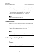
1) Wear the ESD-preventive wrist strap, loosen the captive screws on the blank
panel in the slot where a board should be inserted, and remove the blank panel.
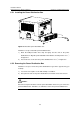
2) Hold the ejector levers on the board with both hands and pull them outward
simultaneously. Slide the board into the slot along the guide rails. Push the board
until the positioning pin touches the hole on the chassis. See ① in
Figure 6-2.
3) Press the ejector levers inward until the ejector levers contact against the board
panel and the board snaps into the backplane. See ② in
Figure 6-2.
4) Fasten the captive screws to fix the board. See ③ in
Figure 6-2.
Note:
Put away the removed blank panel for future use.
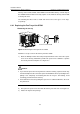
6.3.2 Removing a Board
Follow these steps to remove a board (just in the opposite way you install a board):
1) Wear the ESD-preventive wrist strap and loosen the captive screws on the board
with the screwdriver.
2) Hold the ejector levers on the board with both hands and pull them outward
simultaneously to separate the connectors of the board from the backplane.
3) Gently slide the board along the guide rails out of the slot.
Note:
If you are not going to install a new board after removing the board, install a blank panel
in the slot for dust-proof purpose.
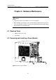
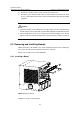
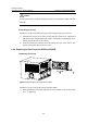
6.4 Removing and Installing a Fan Tray
Caution:
Do not touch any naked wire, terminal, or any part of the product labeled with a high
voltage hazard warning to avoid bodily injury.