
H3C S7500 Series Ethernet Switches Installation Manual

Installation Manual
H3C S7500 Series Ethernet Switches Appendix A B68-22 Cabinet Installation
A-5
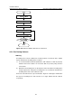
Figure A-6 Cabinet installation flowchart on cement floor
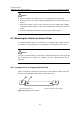
A.2.3 Positioning Cabinets
I. Marking
According to the reference dimensions and the positions of foot bolts in the cabinet
layout, determine the mounting holes as follows:
1) Use an ink fountain to draw two parallel lines, with a distance of 720 cm (28.35 in)
between them and a distance of more than 800 cm (31.50 in) away from the
nearest wall.
2) Determine the mounting holes on the two lines for the first cabinet according to the
design requirements. Using these mounting holes as a benchmark, determine the
mounting holes for the other cabinets in turn.
Re-measure the dimensions to prevent mistakes.
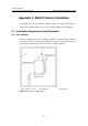
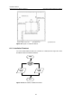
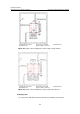
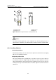
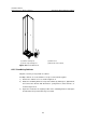
Figure A-7 and Figure A-8 illustrate
the layout of mounting holes and foot bolts for a single cabinet and two cabinets
respectively.