
H3C S7500 Series Ethernet Switches Installation Manual

Installation Manual
H3C S7500 Series Ethernet Switches Appendix A B68-22 Cabinet Installation
A-6
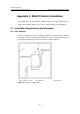
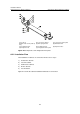
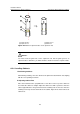
(1) M12 expansion bolt (2) Position of foot bolt (3) Cabinet side
(4) Cabinet rear (5) Inner wall or reference
Figure A-7 Layout of the mounting holes and foot bolts (single cabinet)
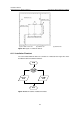
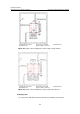
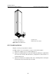
(1) M12 expansion bolt (2) Position of foot bolt (3) Cabinet side
(4) Cabinet rear (5) Inner wall or reference
Figure A-8 Layout of the mounting holes and foot bolts (two cabinets)
II. Drilling holes
Use a percussion drill with a Φ16 bit to drill holes for bolting the anchor plates.