
H3C S7500 Series Ethernet Switches Installation Manual

Installation Manual
H3C S7500 Series Ethernet Switches Appendix A B68-22 Cabinet Installation
A-18
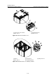
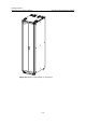
The components I, II and III allow you to adjust height freely within the specified ranges
by moving oppositely the upper and lower racks.
The IV component is for racks with fixed heights that are extremely high or low. The
lowest floor height must be 100 mm (3.9 in).
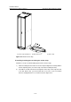
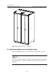
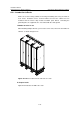
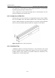
A.3.2 Introduction to Slide Rails
Slide rails allow you to move the device to an appropriate position easily. In addition,
they can join multiple racks and cabinets together, make connections stronger and
keep the cabinets horizontal. As shown in
Figure A-19, a slide rail segment is 600 mm
(23.6 in.) long. The standard shipment includes two segments for each cabinet.
6
0
0
mm
(
2
3
.6
i
n
)
7
5m
m
(
3
i
n)
50mm (2in)
6
0
0
mm
(
2
3
.6
i
n
)
7
5m
m
(
3
i
n)
50mm (2in)
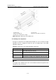
Figure A-19 Dimensions of slide rail segments
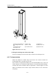
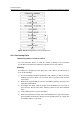
A.3.3 Installation Flow
Installing the cabinet on cement floor includes these steps: Position the racks. Install
the racks. Install the slide rails. Install the floor support accessories. Level the cabinets.
Combine cabinets. Fix the cabinets. Test insulation. Replace the antistatic floor. The
installation flow is shown in
Figure A-20.