
H3C S7500 Series Ethernet Switches Installation Manual

Installation Manual
H3C S7500 Series Ethernet Switches Appendix B N68 Cabinet Installation
B-10
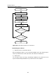
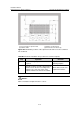
Table B-1 Determine installation hole positions based on the layout
Step Operation Remarks
1
Determine the installation positions of the
expansion bolts according to the
dimensions specified in the construction
plan and the installation hole dimensions.
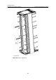
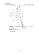
Figure B-9 shows installation
positions of the expansion
bolts and feet for a single
cabinet.
Figure B-10 shows
installation positions of the
expansion bolts and feet
used to combine a row of
cabinets.
2
Mark several points for drawing with a steel
tape, and then draw two straight lines
parallel to the benchmarks, with a spacing
of 687 mm (27.0 in.).
—
3
Determine the hole positions of the
expansion bolts for the first cabinet and foot
positions on the two lines as designed.
—
4
With these holes as reference, mark the
installation hole positions of the expansion
bolts for other cabinets and foot positions.
—
5 Measure and confirm hole sizes again.
—
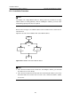
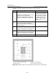
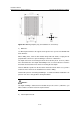
(1) Hole for fixing an expansion bolt (2) Mark for positioning feet
(3) Cabinet outline (4) Inner wall or reference body
Figure B-9 Installation positions of the expansion bolts and feet for a single cabinet