
H3C S7500 Series Ethernet Switches Installation Manual

Installation Manual
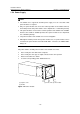
H3C S7500 Series Ethernet Switches Chapter 1 Product Overview
1-16
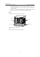
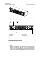
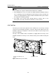
(1) Grounding screw (2) Power switch
(3) Bail latch (4) Power socket
(5) COM port (PSE monitoring port) (6) RTN (+) terminal of PoE power input
(7) NEG (-) terminal of PoE power input (8) Handle on the rear panel
(9) Air filter
Figure 1-9 Rear view of the S7506 chassis (S7506-AC-XG-PoE chassis in the
example)
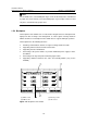
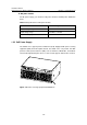
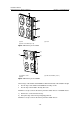
Each area is hot-swappable.
z The board area contains seven horizontal slots. The topmost slot top is for a
required SRPU and the other six slots for optional LPUs.
z The fan area is on the right of a chassis. The fan tray slot is vertical.
z The power supply area is at the bottom of the chassis and contains three power
module slots to implement 2+1 redundancy. You can select AC power modules for
AC power input or DC power modules for DC power input as required.
z The power distribution area is at the chassis bottom near to the back panel. There
is an AC power distribution box for AC power input or a DC power distribution box
for DC power input.
z There are a –48 VDC power input terminal and a COM port (PoE management
port) on the back of the PoE-capable S7506 XGbus chassis.
III. S7506R
Figure 1-10 shows the chassis and slots of the S7506R.