
H3C S7500 Series Ethernet Switches Installation Manual

Installation Manual
H3C S7500 Series Ethernet Switches Appendix B N68 Cabinet Installation
B-38
Note:
The procedure of combining cabinets is optional.
When two or more than two cabinets need to be installed in the same row, they should
be installed side by side.
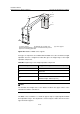
B.3.3 Positioning Supports
I. Determining where to install the cabinet
Before installing the cabinet, you need to plan installation space first. Sufficient space
must be provided in front of and at the back of the cabinet for maintenance.
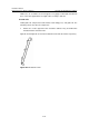
II. Making marks
You can draw lines in two ways: determining installation hole positions based on layout
design and determining installation hole positions based on the template.
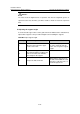
Table B-6 Determine installation hole positions based on the layout
Step Operation Remarks
1
Determine the installation positions of the
supports according to the dimensions
specified in the construction plan and the
installation hole dimensions
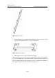
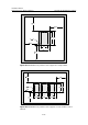
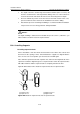
Figure B-37 shows the
installation hole positions
of the supports for a single
cabinet.
Figure B-38
shows the installation hole
positions of the supports
used to combine a row of
cabinets.
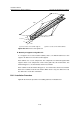
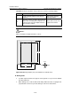
2
Mark several points for drawing with a
steel tape, and then draw two straight
lines parallel to the benchmarks, with the
spacing of 690 mm (27.0 in.).
—
3
Determine the hole positions of the
expansion bolts for the first cabinet on the
two lines as designed.
—
4
With these holes as reference, mark the
installation hole positions of the
expansion bolts for other cabinets.
—
5 Measure and confirm hole sizes again.
Check whether the
supports are aligned with
the holes. If errors are not
acceptable, you must
measure and drill again.