
H3C S7500 Series Ethernet Switches Installation Manual

Installation Manual
H3C S7500 Series Ethernet Switches Appendix B N68 Cabinet Installation
B-40
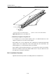
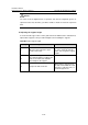
Table B-7 Determine installation hole positions based on the marking template
Step Operation Remarks
1
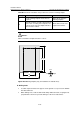
Put the marking template on the floor as
required.
Figure B-39 shows the
marking template.
2
Mark the positions of all the expansion bolts
on the floor according to the template. The
semi-circle notch of the template indicates
the front of the cabinet.
Each cabinet needs four
expansion bolt holes.
Caution:
Make sure that the template direction is correct.
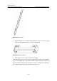
Front
Back
RightLeft
800
354
600
690
Figure B-39 Marking template (only for installation on antistatic floor)
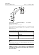
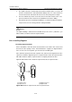
III. Drilling holes
z Use M12 expansion bolts to fix supports on the ground. Use a percussion drill with
Ф16 bit to drill holes.
z When drilling holes, hold the drill handle firmly with both hands, keeping the bit
perpendicular to the floor to prevent damages to the floor or tilted holes.