
H3C S7500 Series Ethernet Switches Installation Manual

Installation Manual
H3C S7500 Series Ethernet Switches Appendix B N68 Cabinet Installation
B-41
z The depth of the holes should range from 52 mm to 60 mm (2.0 in. to 2.4 in.). All
the holes should have the same depth. After drilling a hole, use a dust collector to
clean the dust inside and outside the holes before measuring the hole depth.
z The bit is difficult to position on the floor that is hard and smooth. In this case,
punch a small hole on the marks for the installation holes before drilling.
z Note that the precision of marking and drilling is essential to hardware installation.
Low precision can cause many problems during installation.
Caution:
The depth of drilling is between 52 mm and 60 mm (2.0 in. to 2.4 in.). Otherwise, you
will be unable to install or fasten the expansion bolts.
B.3.4 Installing Supports
I. Installing expansion bolts
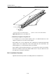
Prior to installation, clean dust inside and outside the holes with a dust collector and
then measure the spacing of holes. Check whether the supports are aligned with the
holes. If errors are not acceptable, you must measure and drill again.
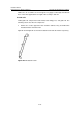
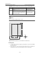
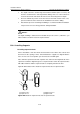
Take down the expansion tube and expansion nut, and insert the alignment rib on the
expansion nut into the alignment groove of expansion tube. Punch the expansion tube
with rubber hammer until the expansion tube is completely buried in the floor.
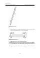
Figure B-40 illustrates how to install an expansion nut onto an expansion tube.
1
2
3
4
(1) Expansion tube (2) Alignment groove
(3) Expansion nut (4) Alignment rib
Figure B-40 Install an expansion nut onto an expansion tube